Hindawi Publishing Corporation VLSI Design Volume 2013, Article ID 206909, 11 pages http://dx.doi.org/10.1155/2013/206909
Research Article Low Complexity Submatrix Divided MMSE Sparse-SQRD Detection for MIMO-OFDM with ESPAR Antenna Receiver Diego Javier Reinoso Chisaguano and Minoru Okada Graduate School of Information Science, Nara Institute of Science and Technology, 8916-5 Takayama, Ikoma-shi, Nara 630-0192, Japan Correspondence should be addressed to Diego Javier Reinoso Chisaguano;
[email protected] Received 1 November 2012; Accepted 6 April 2013 Academic Editor: Mohamed Masmoudi Copyright © 2013 D. J. Reinoso Chisaguano and M. Okada. This is an open access article distributed under the Creative Commons Attribution License, which permits unrestricted use, distribution, and reproduction in any medium, provided the original work is properly cited. Multiple input multiple output-orthogonal frequency division multiplexing (MIMO-OFDM) with an electronically steerable passive array radiator (ESPAR) antenna receiver can improve the bit error rate performance and obtains additional diversity gain without increasing the number of Radio Frequency (RF) front-end circuits. However, due to the large size of the channel matrix, the computational cost required for the detection process using Vertical-Bell Laboratories Layered Space-Time (V-BLAST) detection is too high to be implemented. Using the minimum mean square error sparse-sorted QR decomposition (MMSE sparse-SQRD) algorithm for the detection process the average computational cost can be considerably reduced but is still higher compared with a conventional MIMOOFDM system without ESPAR antenna receiver. In this paper, we propose to use a low complexity submatrix divided MMSE sparse-SQRD algorithm for the detection process of MIMOOFDM with ESPAR antenna receiver. The computational cost analysis and simulation results show that on average the proposed scheme can further reduce the computational cost and achieve a complexity comparable to the conventional MIMO-OFDM detection schemes.
1. Introduction In multipath fading channels, multiple input multiple output (MIMO) antenna systems can achieve a great increase in the channel capacity [1]. MIMO-OFDM combines the advantages of the MIMO systems with orthogonal frequency division multiplexing (OFDM) modulation, achieving a good performance for frequency selective fading channels. Due to these advantages, MIMO-OFDM allows high data rates in wireless communications systems. It is used in the wireless local area network (WLAN) standard IEEE 802.11n [2] and is also considered for the next-generation systems. One of the limitations of MIMO-OFDM is that it requires one radio frequency (RF) front-end circuit for every receiver and transmitter antenna. Comparing MIMO-OFDM 2Tx2Rx with MIMO-OFDM 2Tx-4Rx, MIMO-OFDM 2 × 4 can achieve better diversity gain and bit error rate performance but requires more RF front-end circuits, A/D converters, and FFT blocks for every additional branch. In [3, 4] a MIMO-OFDM 2 × 2 scheme with electronically steerable passive array radiator (ESPAR) antenna receiver
diversity has been proposed. It utilizes for every receiver a 2-element ESPAR antenna whose directivity is changed at the same frequency of the OFDM symbol rate. Compared to the conventional MIMO-OFDM 2 × 2 systems, this scheme gives additional diversity gain and improves the bit error rate performance without increasing the number of RF frontend circuits. For the detection the zero forcing (ZF) VerticalBell Laboratories Layered Space-Time (V-BLAST) algorithm [5, 6] is used but, due to the large size of the channel matrix, the required computational effort is very high. In order to reduce the computational cost of the detection process of the scheme proposed in [3, 4], the use of a minimum mean square error sparse-sorted QR decomposition (MMSE sparse-SQRD) algorithm based on the SQRD algorithm introduced in [7, 8] was proposed by the authors in [9]. The computational cost reduction is achieved by exploiting the sparse structure of the channel matrix. This detection algorithm considerably reduces the average computational cost and also improves the bit error rate performance compared to the original scheme [3, 4]. A submatrix divided MMSE sparse-SQRD algorithm for the
2
VLSI Design Radiator
Parasitic element
Ground plane
Tx 1 Baseband OFDM demodulator Channel estimator
RF front-end
𝐴/𝐷
𝑓 = OFDM symbol rate
Frequency domain equalizer
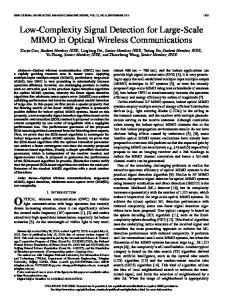
Figure 1: Block diagram of OFDM receiver with ESPAR antenna.
detection process of MIMO-OFDM with ESPAR antenna receiver was proposed by the authors in [10] for further reduction in the computational cost. This algorithm divides the channel matrix into 𝑘 smaller submatrices reducing the computational cost but adding a small degradation in the bit error rate performance. This paper is an extension of [10] including results of the bit error performance and computational cost for higher order submatrix division schemes. Also, another approach to further reduce the bit error degradation originated by the submatrix division algorithm is introduced. The rest of this paper is organized as follows. Sections 2 and 3 gives a brief background description about OFDM and MIMO-OFDM with ESPAR antenna receiver. In Section 4, detection algorithms based on QR decomposition are shown. Then in Section 5 a detailed explanation about the MMSE sparse-SQRD algorithm is included. In Section 6 the proposed submatrix divided scheme is described. The computational cost analysis and simulation results are presented in Sections 7 and 8, respectively. And finally, in Section 9 conclusions are included.
2. OFDM with ESPAR Antenna ESPAR is a small size and low power consumption antenna [11, 12]. It is composed by a radiator element connected to the RF front-end and one or more parasitic (passive) elements terminated by variables capacitances. The beam directivity can be controlled modifying the variables capacitances. This antenna requires only one RF front-end and therefore is known also as single RF port antenna array. In [13] an OFDM receiver using ESPAR antenna is proposed. In this scheme the directivity of the ESPAR antenna is changed by a periodic wave whose frequency is the OFDM symbol rate. The block diagram of this scheme is shown in Figure 1. A two-element ESPAR antenna is utilized. The periodic variation of the directivity causes intercarrier interference (ICI) in the received signal. The ICI is caused by the addition of phase shifted components to the received signal. The frequency domain equalizer in Figure 1 uses both the shifted and nonshifted components in the detection. Due to this effect this scheme obtains diversity gain, therefore improving the bit error rate performance.
IFFT
GI
𝐷/𝐴
Mod
IFFT
GI
𝐷/𝐴
Input Tx 2
FFT
Variable capacitance
Mod
Figure 2: Block diagram of the MIMO-OFDM transmitter.
3. MIMO-OFDM with ESPAR Antenna Receiver Based on [13], a MIMO-OFDM receiver with ESPAR antenna was proposed in [3, 4] and is described in this section. The block diagrams of the receiver and transmitter are shown in Figures 2 and 3, respectively. The transmitter is based on the WLAN standard IEEE 802.11n [2]. For simplicity forward error correction (FEC) interleaver blocks are not considered in the system. The receiver uses a 2-element ESPAR antenna where the directivity is also periodically changed according to the OFDM symbol rate. An MMSE channel estimator derived in [3, 4] is used and the detection process is carried out by the ZF VBLAST detector. 3.1. Channel Estimation. For the channel estimation [13], let P1 be the pilot symbol and its cyclic shifted P2 . The received signal after the FFT processor at the 𝑖th Rx is 𝑠 𝑛𝑠 𝑠 ui = P1 h𝑛𝑠 𝑖,1 + GP1 h𝑖,1 + P2 h𝑖,2 + GP2 h𝑖,2 + z,
h𝑛𝑠 𝑖,𝑙
(1)
h𝑠𝑖,𝑙
where and are the channel response between the 𝑖th receive antenna and lth transmit antenna for the phase nonshifting (ns) and phase shifting (s) elements respectively. The matrix G represents the frequency shift due to directivity variation in ESPAR antenna and z is the additive white Gaussian noise (AWGN) vector. From (1) the autocorrelation matrix Ru = 𝐸[u𝑖 u𝐻 𝑖 ] is given by 𝐻 𝐻 Ru = P1 Rℎ P𝐻 1 + GP1 Rℎ P1 G 𝐻 𝐻 2 + P2 Rℎ P𝐻 2 + GP2 Rℎ P2 G + 𝜎𝑧 I,
(2)
where 𝜎𝑧2 is the noise variance and Rℎ is the covariance matrix that represents the delay profile of the channel. Considering that the phase nonshifting (ns) and phase shifting (s) elements are spatially separated enough to be uncorrelated, the crosscorrelation matrices B𝑖 = 𝐸[uh𝐻] are given by B𝑛𝑠 𝑖 = P𝑖 Rℎ , B𝑠𝑖 = GP𝑖 Rℎ .
(3)
Using the MMSE criteria the channel response is given by ̃ 𝑛𝑠 = (R −1 B𝑛𝑠 )𝐻u , h u 𝑖 𝑖,𝑙 𝑖 ̃ 𝑠 = (R −1 B𝑠 )𝐻u . h u 𝑖 𝑖,𝑙 𝑖
(4)
VLSI Design
3 Rx 1
𝑟2
RF front-end
𝐴/𝐷
GI
FFT
𝑢1
Channel estimator Rx 2
𝑟1
RF front-end
𝐴/𝐷
GI
FFT
ZF VBLAST
𝑃/𝑆
Dem
𝑢2
Figure 3: Block diagram of the MIMO-OFDM receiver with ESPAR antenna.
The channel matrix H has a size of 2(𝑁 + 2) × 2𝑁, where 𝑁 is the number of data subcarriers. 3.2. Detection. For the detection process the ZF V-BLAST [6] algorithm is used. In this algorithm the received signal vector is multiplied with a filter matrix GZF , that is, calculated by GZF = H† ,
(5)
where H† is the Moore-Penrose pseudoinverse of H. The matrix GZF is calculated in a recursive way after zeroing one column of the channel matrix H; for this scheme the pseudoinverse is calculated 2N times. Due to the large size of the channel matrix H, calculating the pseudoinverse demands a very high computational effort and for this reason the detection process is the main limitation of this scheme.
where Q is a unitary matrix and R is an upper triangular matrix. And the extended vector of received symbols u is given by u = QRx + z.
(8)
Then (8) is multiplied by Q𝐻 to obtain y = Q𝐻u = Rx + ^,
(9)
where Q𝐻 is the Hermitian transpose of Q and ] = Q𝐻𝑧. The statistical properties of ] remain unchanged because Q is a unitary matrix.
4. QR Decomposition-Based Detection Let x = [𝑥1 , 𝑥2 , . . . , 𝑥2𝑁]𝑇 denote the vector of transmitted symbols, let z = [𝑧1 , 𝑧2 , . . . , 𝑧2(𝑁+2) ]𝑇 denote the vector of noise components and u = [𝑢1 , 𝑢2 , . . . , 𝑢2(𝑁+2) ]𝑇 the vector of received symbols. 4.1. MMSE-QRD. Applying like in [8] the MMSE detector criteria, let us denote the extended channel matrix H and the extended vector of received symbols u by H=[
H ], 𝜎𝑧 I2𝑁
u=[
u 02𝑁,1
(6)
],
where 𝜎𝑧 is the noise standard deviation, I2𝑁 is an identity matrix of size 2𝑁 × 2𝑁, and 02𝑁,1 is a column vector with 2𝑁 zero elements. The QR decomposition of the extended channel matrix H can be expressed by H = QR,
(7)
4.2. MMSE-SQRD. In [8] an MMSE sorted QRD detection algorithm based on the modified Gram-Schmidt algorithm is introduced. The starting condition is that Q = H; then the norms of the column vectors of Q are calculated. For every step the column of Q with the minimum norm is found to maximize R𝑘,𝑘 and the columns of Q are exchanged before the orthogonalization process. This algorithm calculates an improved matrix R that reduces the error propagation through the detection layers. During the calculation, a permutation vector p carries the column exchanging operations for reordering the detected symbols at the end of the algorithm. After the matrices R and Q are calculated, then y is obtained according to (9) and the symbols are detected iteratively. After the symbols are detected, they are reordered using the permutation vector p to find the original sequence of the detected symbols.
5. MMSE Sparse-SQRD Algorithm The extended channel matrix H whose size is 2(2𝑁 + 2) × 2𝑁 is shown in (10) and as we can see it is a sparse matrix. The MMSE sparse-SQRD algorithm is based on the MMSE-
4
VLSI Design
SQRD algorithm [8] and exploits the sparse structure of H to reduce the computational cost of the detection process: 𝑛𝑠 𝐻𝐴,−𝑁/2 𝑠 (𝐻𝐴,−𝑁/2 ( ( ( ( 0 ( ( ( ( . ( . . ( ( ( ( ( 0 ( ( ( 𝑛𝑠 (𝐻𝐶,−𝑁/2 ( ( ( ( ( 𝑠 (𝐻𝐶,−𝑁/2 ( H=( ( 0 ( ( ( ( ( . . ( . ( ( ( ( 0 ( ( ( ( 𝜎 ( 𝑧 ( ( ( 0 ( ( ( ( . ( .. (
(
0
⋅⋅⋅
0
𝑛𝑠 𝐻𝐵,−𝑁/2
⋅⋅⋅
0
d d
. . .
𝑠 𝐻𝐵,−𝑁/2 d d
. . .
d d
0
0
d d
𝑛𝑠 𝐻𝐴,𝑁/2
. . .
d d
⋅⋅⋅
0
𝑠 𝐻𝐴,𝑁/2
0
⋅⋅⋅
0
0
⋅⋅⋅
0
𝑛𝑠 𝐻𝐷,−𝑁/2
0
⋅⋅⋅
d d
. . .
𝑠 𝐻𝐷,−𝑁/2 d d
d d
0
0
0
d d
0
d d
𝑛𝑠 d d 𝐻𝐶,𝑁/2
. . .
d d
0
⋅⋅⋅
0
⋅⋅⋅
0
𝑠 𝐻𝐶,𝑁/2
0
⋅⋅⋅
⋅⋅⋅
⋅⋅⋅
⋅⋅⋅
0
𝜎𝑧
0
⋅⋅⋅
⋅⋅⋅
⋅⋅⋅
0
d d
d
⋅⋅⋅
⋅ ⋅ ⋅ 𝜎𝑧
⋅⋅⋅ ⋅⋅⋅
⋅⋅⋅
⋅⋅⋅
⋅⋅⋅
0
) ) ) ) 0 ) ) ) ) ) ) 𝑛𝑠 𝐻𝐵,𝑁/2 ) ) ) ) 𝑠 𝐻𝐵,𝑁/2 ) ) ) ) 0 ) ) ) ) . ) . ) . ) ) ) 0 ) ) ) ) ) ) 𝑛𝑠 𝐻𝐷,𝑁/2 ) ) ) ) 𝑠 𝐻𝐷,𝑁/2 ) ) ) ) 0 ) ) ) ) 0 ) ) ) ) ) ) 0 ) 𝜎𝑧
)
(10) Analysing H given in (10) we can see that every column has only five nonzero elements so for the norm calculation of the column vectors of Q only these elements should be used. Also the positions of the nonzero elements are fixed so we have this information contained in a matrix as input. Using this information the norm calculation is shown in lines 5–9 of Algorithm 1. In the orthogonalization process of the algorithm these two calculations 𝑟𝑖,𝑙 = q𝐻q , 𝑖
(11)
𝑙
q = q − 𝑟𝑖,𝑙 q 𝑙
𝑙
𝑖
(12)
are performed in an iterative way. 𝑟𝑖,𝑙 denote the elements of the matrix R and q , q are column vectors of the matrix Q. 𝑙 𝑖 In (11), the multiplication of the zero elements of the column vectors does not influence the final result so these multiplications can be avoided. A vector containing only the indices of the nonzero elements of the column vectors is obtained in line 14 so the number of operations required to calculate 𝑟𝑖,𝑙 is reduced without influencing the final result. This is shown in lines 19–21 in the algorithm. The same strategy is used also in lines 15–17 and 23–25. Also, due to the sparse structure of (10), the result of (11) can be zero. In this case calculating (12) is unnecessary because it does not change the value of q so it can be avoided 𝑙 using the condition in line 22.
1: Input: H, Hnz 2: 𝑐𝑜𝑙𝑠 ← # of columns of H 3: 𝑟𝑜𝑤𝑠 ← # of rows of H 4: R = 0, Q = H, p = (1, . . ., cols) 5: for 𝑖 = 1, . . . , 𝑐𝑜𝑙𝑠 do 6: for 𝑗 = 1, . . . , 5 do 7: norm𝑖 := norm𝑖 + ‖ 𝑞
𝐻𝑛𝑧(𝑗,𝑖),𝑖
‖2
8: end for 9: end for 10: for 𝑖 = 1, . . . , 𝑐𝑜𝑙𝑠 do 11: 𝑘𝑖 = arg min𝑙=𝑖,...,𝑐𝑜𝑙𝑠 norm𝑙 12: exchange columns 𝑖 and 𝑘𝑖 in R, Q, norm, p 13: 𝑟𝑖,𝑖 = √norm𝑖 14: nz ← indices of the non-zero elements of q 𝑖 15: for 𝑗 = 1, . . . , 𝑙𝑒𝑛𝑔𝑡ℎ(nz) do := 𝑞 /𝑟𝑖,𝑖 16: 𝑞 𝑛𝑧(𝑗),𝑖
17: 18: 19: 20: 21: 22: 23: 24:
𝑛𝑧(𝑗),𝑖
end for for 𝑙 = 𝑖 + 1, . . . , 𝑐𝑜𝑙𝑠 do for 𝑗 = 1, . . . , 𝑙𝑒𝑛𝑔𝑡ℎ(nz) do 𝑟𝑖,𝑙 := 𝑟𝑖,𝑙 + (𝑞∗
𝑛𝑧(𝑗),𝑖
)𝑞
𝑛𝑧(𝑗),𝑙
end for if 𝑟𝑖,𝑙 ≠ 0 then for 𝑗 = 1, . . . , 𝑙𝑒𝑛𝑔𝑡ℎ(nz) do := 𝑞 − 𝑟𝑖,𝑙 𝑞 𝑞 𝑛𝑧(𝑗),𝑙
𝑛𝑧(𝑗),𝑙
𝑛𝑧(𝑗),𝑖
25: end for 26: norm𝑙 := norm𝑙 − ‖ 𝑟𝑖,𝑙 ‖2 27: end if 28: end for 29: end for 30: Q1 ← Q(1 : 𝑟𝑜𝑤𝑠 − 𝑐𝑜𝑙𝑠, :) 31: y = Q𝐻 1 u 32: for 𝑘 = 𝑐𝑜𝑙𝑠, . . . , 1 do 𝑐𝑜𝑙𝑠 33: 𝑑̂ = ∑𝑖=𝑘+1 𝑟𝑘,𝑖 x̂𝑖 ̂ 34: x̂𝑘 = Q [(y𝑘 − 𝑑)/𝑟 𝑘,𝑘 ] 35: end for 36: Permutate x̂ according to p Algorithm 1: MMSE sparse-SQRD.
Also we can consider that the calculation of (9) can be simplified as y = Q𝐻 u = [
𝐻
Q1 u ] [ ] = Q𝐻 1 u, Q2 02𝑁,1
(13)
where Q1 is a matrix with the same size of the channel matrix H. This is shown in lines 30-31 of the algorithm. Using these analysed criteria the MMSE sparse-SQRD algorithm can achieve the same bit error rate performance of the MMSE-SQRD algorithm but with a considerable computational cost reduction.
6. Submatrix Divided Proposed Algorithm In order to further reduce the computational cost of the detection process an algorithm based on submatrix division
VLSI Design
5
of the channel matrix is proposed. The block diagram of the proposed scheme is shown in Figure 4. This detection scheme is composed by a submatrix builder block and 𝑘 MMSE sparse-SQRD detectors. The submatrix builder is fed with the received symbols from the FFT processors and the channel state information obtained in the channel estimator. Its function is to build the submatrices and vectors for the detectors. Every detector is fed with a vector of received symbols s𝑖 and a channel submatrix H𝑖 . From now on we consider the number of subcarriers to be 𝑁 = 56 like in the IEEE 802.11n [2] standard. Let a = [𝑎1 , 𝑎2 , . . . , 𝑎58 ]𝑇 denote the vector of received (transmitted and interfered) symbols from the FFT1 processor and let b = [𝑏1 , 𝑏2 , . . . , 𝑏58 ]𝑇 denote the vector of received symbols from the FFT2 processor. For simplicity we consider that the extended channel submatrix H𝑖 is created inside the 𝑖th detector. Now we will explain in detail the submatrix division case when 𝑘 = 4 considering two variations with 2 or 4symbol overlapping.
𝑛𝑠 𝐻𝐴,+1
H32
𝑠 (𝐻𝐴,+1 ( ( ( ( 0 ( ( ( ( 0 ( ( =( 𝑛𝑠 (𝐻𝐶,+1 ( ( ( ( ( 𝑠 (𝐻𝐶,+1 ( ( ( ( 0
(
𝑠 (𝐻𝐴,−28 ( ( ( ( 0 ( ( ( ( 0 ( ( =( 𝑛𝑠 (𝐻𝐶,−28 ( ( ( ( ( 𝑠 (𝐻𝐶,−28 ( ( ( ( 0
(
0
⋅⋅⋅
0
𝑛𝑠 𝐻𝐵,−28
d
d
. ..
𝑠 𝐻𝐵,−28 d
𝑛𝑠 d 𝐻𝐴,−15
⋅⋅⋅
d
⋅⋅⋅
0
d
. ..
0
𝑛𝑠 d 𝐻𝐵,−15
𝑛𝑠 𝐻𝐴,−14
0
⋅⋅⋅
𝑠 𝐻𝐵,−15
...
0
𝑛𝑠 𝐻𝐷,−28
0
⋅⋅⋅
d
. . .
𝑠 𝐻𝐴,−15
0
0
𝑛𝑠 d 𝐻𝐶,−15
0
0
𝑠 𝑛𝑠 𝐻𝐶,−14 ⋅ ⋅ ⋅ 𝐻𝐶,−15
𝑠 𝐻𝐷,−28 d
d
) ) ) ) 0 ) ) ) ) 𝑛𝑠 ) 𝐻𝐵,−14 ) ) ), 0 ) ) ) ) . ) . ) . ) ) ) ) 0 )
0
𝑛𝑠 d 𝐻𝐷,−15
0
𝑠 𝑛𝑠 ⋅ ⋅ ⋅ 𝐻𝐷,−15 𝐻𝐷,−14
)
(14) 𝑛𝑠 0 𝐻𝐴,−14 𝑠
H22
(𝐻𝐴,−14 ( ( ( 0 ( ( ( 0 ( ( =( 𝑛𝑠 (𝐻𝐶,−14 ( ( ( ( 𝑠 (𝐻𝐶,−14 ( ( ( 0 (
0
0
0
𝑛𝑠 𝐻𝐵,+1
d
d
. ..
𝑠 𝐻𝐵,+1 d
𝑛𝑠 d 𝐻𝐴,+14
0
𝑠 𝑛𝑠 ⋅ ⋅ ⋅ 𝐻𝐴,+14 𝐻𝐴,+15
d
. .. 0
0
𝑠 ⋅ ⋅ ⋅ 𝐻𝐵,+14
𝑛𝑠 𝐻𝐵,15
𝑛𝑠 𝐻𝐷,+1
d
d
. . .
𝑠 𝐻𝐷,+1 d
0
0
𝑛𝑠 d 𝐻𝐵,+14
0
𝑛𝑠 d 𝐻𝐶,+14
⋅⋅⋅
0
⋅⋅⋅
𝑠 𝑛𝑠 ⋅ ⋅ ⋅ 𝐻𝐶,+14 𝐻𝐶,+15
0
0
0
𝑛𝑠 0 𝐻𝐴,+15 𝑠
H12 0
⋅⋅⋅
0
⋅⋅⋅
0
d
. . .
0
𝑛𝑠 d 𝐻𝐷,+14
0
𝑠 𝑛𝑠 ⋅ ⋅ ⋅ 𝐻𝐷,+14 𝐻𝐷,+15
H42
(𝐻𝐴,+15 ( ( ( 0 ( ( ( 0 ( ( =( 𝑛𝑠 (𝐻𝐶,+15 ( ( ( ( 𝑠 (𝐻𝐶,+15 ( ( ( 0 (
0
0
𝑛𝑠 𝐻𝐵,+15 0
0
d
.. .
𝑠 𝐻𝐵,+15 d
.. .
d
𝑛𝑠 𝐻𝐴,+28
0
𝑠 ⋅ ⋅ ⋅ 𝐻𝐴,+28
0
d
𝑛𝑠 d 𝐻𝐶,+28
0
𝑠 ⋅ ⋅ ⋅ 𝐻𝐶,+28
0
𝑠 ⋅ ⋅ ⋅ 𝐻𝐷,+28
0
0
𝑛𝑠 𝐻𝐷,+15
d
.. .
𝑠 𝐻𝐷,+15
𝑇
𝑇
𝑠 𝐻𝐵,−14 d
s3 2 = [𝑎30 , . . . , 𝑎44 , 𝑏30 , . . . , 𝑏44 ] ,
0
𝑠 ⋅ ⋅ ⋅ 𝐻𝐴,−1
0
d
) )
𝑛𝑠 ) 𝐻𝐵,−1 ) )
𝑛𝑠 d 𝐻𝐶,−1
0
𝑠 ⋅ ⋅ ⋅ 𝐻𝐶,−1
0
𝑠 ⋅ ⋅ ⋅ 𝐻𝐷,−1
0
𝑛𝑠 𝐻𝐷,−14
d
.. .
𝑠 𝐻𝐷,−14
(18)
𝑇
) 𝑠 ) ⋅ ⋅ ⋅ 𝐻𝐵,−1 ) ) ) , (15) 0 0 ) ) ) .. ) ) d . ) ) ) 𝑛𝑠 ) d 𝐻𝐷,−1
0
(17)
s1 2 = [𝑎1 , . . . , 𝑎15 , 𝑏1 , . . . , 𝑏15 ] ,
.. .
d
)
The vectors of received symbols applied to the four detectors are denoted as
s2 2 = [𝑎15 , . . . , 𝑎29 , 𝑏15 , . . . , 𝑏29 ] ,
𝑛𝑠 𝐻𝐴,−1
) )
) 𝑠 ) ⋅ ⋅ ⋅ 𝐻𝐵,+28 ) ) ). 0 0 ) ) ) .. ) ) d . ) ) ) ) 𝑛𝑠 d 𝐻𝐷,+28
0
d
)
) 𝑛𝑠 𝐻𝐵,+28 ) )
𝑛𝑠 𝐻𝐵,−14 0
.. .
0
) ) ) ) ) ) ) ) ) ) ) ), ) ) ) ) ) ) ) ) ) ) )
(16)
6.1. Quarter-Size Submatrix (𝑘 = 4) with 2-Symbol Overlapping. In this case we divide the channel matrix into four submatrices denoted as H12 , H22 , H32 and H42 . These matrices are shown in (14), (15), (16), and (17), respectively,
𝑛𝑠 𝐻𝐴,−28
0
)
𝑇
s4 2 = [𝑎44 , . . . , 𝑎58 , 𝑏44 , . . . , 𝑏58 ] . And the vectors of detected symbols obtained from the detectors are denoted as 𝑇
x1 2 = [𝑥1 , . . . , 𝑥14 , 𝑥15 , 𝑥57 , . . . , 𝑥70 , 𝑥71 ] , 𝑇
x2 2 = [𝑥15 , . . . , 𝑥28 , 𝑥71 , . . . , 𝑥84 ] , 𝑇
x3 2 = [𝑥29 , . . . , 𝑥42 , 𝑥43 , 𝑥85 , . . . , 𝑥98 , 𝑥99 ] , 𝑇
x4 2 = [𝑥43 , . . . , 𝑥56 , 𝑥99 , . . . , 𝑥112 ] .
(19)
6
VLSI Design 𝑠1 𝐻1
···
FFT
.. .
···
Sub-matrix builder
1
Channel estimator
𝑠𝑘/2 𝐻𝑘/2
Det
𝑘/2 𝑃/𝑆
𝑠𝑘/2+1 𝐻𝑘/2+1
FFT 2
Det 1
𝑠𝑘 𝐻𝑘
Demod
Det 𝑘/2 + 1 .. .
6.2. Quarter-Size Submatrix (𝑘 = 4) with 4-Symbol Overlapping. In this subsection another variation with 4-symbol overlapping is introduced. The objective of this idea is to further reduce the degradation in the bit error rate performance created by the submatrix division. Similar to the previous subsection we divide the channel matrix into four submatrices denoted as H14 , H24 , H34 , and H44 . These matrices are shown in (23), (24), (25), and (26), respectively. In this case the vectors of received symbols applied to the four detectors are denoted as 𝑇
s1 4 = [𝑎1 , . . . , 𝑎15 , 𝑎16 , 𝑏1 , . . . , 𝑏15 , 𝑏16 ] ,
Det 𝑘
𝑇
s2 4 = [𝑎15 , 𝑎16 , . . . , 𝑎29 , 𝑏15 , 𝑏16 . . . , 𝑏29 ] ,
(22)
𝑇
s3 4 = [𝑎30 , . . . , 𝑎44 , 𝑎45 , 𝑏30 , . . . , 𝑏44 , 𝑏45 ] ,
Figure 4: Block diagram of the submatrix division proposed scheme.
𝑇
s4 4 = [𝑎44 , 𝑎45 , . . . , 𝑎58 , 𝑏44 , 𝑏45 , . . . , 𝑏58 ] , The submatrix division introduces a degradation in the bit error performance so now we explain the procedure used to minimize this effect. First the channel matrix nonshifted (ns) elements associated with the subcarrier −14 𝑛𝑠 𝑛𝑠 𝑛𝑠 𝑛𝑠 ; 𝐻𝐵,−14 ; 𝐻𝐶,−14 ; 𝐻𝐷,−14 ) are included in both H12 and (𝐻𝐴,−14 H22 . In the same way the nonshifted elements associated 𝑛𝑠 𝑛𝑠 𝑛𝑠 𝑛𝑠 ; 𝐻𝐵,+15 ; 𝐻𝐶,+15 ; 𝐻𝐷,+15 ) are with the subcarrier +15 (𝐻𝐴,+15 included in H32 and H42 . We overlap the symbols 𝑎15 , 𝑏15 in vectors s1 2 and s2 2 . Using the information from the detection process of the detector 1, the symbols 𝑎15 , 𝑏15 in vector s2 2 are compensated according to (20) where 𝑎̃15 , ̃𝑏15 represent the compensated symbols: 𝑠 𝑠 𝑥14 − 𝐻𝐵,−15 𝑥70 , 𝑎̃15 = 𝑎15 − 𝐻𝐴,−15
̃𝑏 = 𝑏 − 𝐻𝑠 𝑥 − 𝐻𝑠 15 15 𝐶,−15 14 𝐷,−15 𝑥70 .
(20)
H14 𝑛𝑠 𝐻𝐴,−28 𝑠 (𝐻𝐴,−28 ( ( ( ( 0 ( ( ( ( 0 ( ( =( 𝑛𝑠 (𝐻𝐶,−28 ( ( ( ( ( 𝑠 (𝐻𝐶,−28 ( ( ( ( 0
(
0
0
⋅⋅⋅
0
𝑛𝑠 𝐻𝐵,−28
d
d
. . .
𝑠 𝐻𝐵,−28 d
𝑛𝑠 d 𝐻𝐴,−14
0
𝑠 𝑛𝑠 ⋅ ⋅ ⋅ 𝐻𝐴,−14 𝐻𝐴,−13
0
d
. . .
𝑛𝑠 d 𝐻𝐵,−14
0
𝑠 ⋅ ⋅ ⋅ 𝐻𝐵,−14
⋅⋅⋅
0
𝑛𝑠 𝐻𝐷,−28
d
d
. ..
𝑠 𝐻𝐷,−28 d
d
𝑛𝑠 𝐻𝐶,−14
𝑠 𝑛𝑠 𝐻𝐶,−13 ⋅ ⋅ ⋅ 𝐻𝐶,−14
0
0
0
0
⋅⋅⋅
0
⋅⋅⋅ d 𝑛𝑠 𝐻𝐷,−14
) ) ) ) 0 ) ) ) ) 𝑛𝑠 ) 𝐻𝐵,−13 ) ) ), 0 ) ) ) ) . ) .. ) ) ) ) ) 0 )
0
d
0
𝑠 𝑛𝑠 ⋅ ⋅ ⋅ 𝐻𝐷,−14 𝐻𝐷,−13
We also overlap symbols 𝑎44 , 𝑏44 in s3 2 and s4 2 . The symbols 𝑎44 , 𝑏44 in vector s4 2 are compensated according to (21) using the information of the detection process of the detector 3. Similarly 𝑎̃44 and ̃𝑏44 represent the compensated symbols: 𝑠 𝑠 𝑎̃44 = 𝑎44 − 𝐻𝐴,+14 𝑥42 − 𝐻𝐵,+14 𝑥98,
̃𝑏 = 𝑏 − 𝐻𝑠 𝑥 − 𝐻𝑠 44 44 𝐶,+14 42 𝐷,+14 𝑥98 .
(23)
𝑛𝑠 0 𝐻𝐴,−14
(21)
During the sorting process of the detector 1, the columns containing the channel matrix nonshifted (ns) elements associated with the subcarrier −14 are used first regardless of its norm. It reduces the degradation introduced by these elements in the upper layers during the detection process. The same is performed in the detector 3 with the nonsubcarriershifted elements of the subcarrier +15. In the vectors of detected symbols the overlapped detected elements 𝑥15 , 𝑥71 in vector x1 2 and 𝑥43 , 𝑥99 in vector x3 2 are discarded because they have a higher probability of error.
)
𝑠
H24
(𝐻𝐴,−14 ( ( ( 0 ( ( ( 0 ( ( =( 𝑛𝑠 (𝐻𝐶,−14 ( ( ( ( 𝑠 (𝐻𝐶,−14 ( ( ( 0 (
0
0
𝑛𝑠 𝐻𝐵,−14 0
0
d
.. .
𝑠 𝐻𝐵,−14 d
.. .
d
𝑛𝑠 𝐻𝐴,−1
0
𝑠 ⋅ ⋅ ⋅ 𝐻𝐴,−1
0
d
) )
𝑛𝑠 ) 𝐻𝐵,−1 ) )
𝑛𝑠 d 𝐻𝐶,−1
0
) 𝑠 ) ⋅ ⋅ ⋅ 𝐻𝐵,−1 ) ) ) , (24) 0 0 ) ) ) .. ) ) d . ) ) ) 𝑛𝑠 ) d 𝐻𝐷,−1
𝑠 ⋅ ⋅ ⋅ 𝐻𝐶,−1
0
𝑠 ⋅ ⋅ ⋅ 𝐻𝐷,−1
0
0
𝑛𝑠 𝐻𝐷,−14
d
.. .
𝑠 𝐻𝐷,−14
)
VLSI Design
7
𝑛𝑠 𝐻𝐴,+1
H34
𝑠 (𝐻𝐴,+1 ( ( ( ( 0 ( ( ( ( 0 ( ( =( 𝑛𝑠 (𝐻𝐶,+1 ( ( ( ( ( 𝑠 (𝐻𝐶,+1 ( ( ( ( 0
(
0
0 d
⋅⋅⋅
0
𝑛𝑠 𝐻𝐵,+1
d
. . .
𝑠 𝐻𝐵,+1 d
𝑛𝑠 d 𝐻𝐴,+15
0
𝑠 𝑛𝑠 ⋅ ⋅ ⋅ 𝐻𝐴,+15 𝐻𝐴,+16
0
. . . 0
0
𝑠 ⋅ ⋅ ⋅ 𝐻𝐵,+15
𝑛𝑠 𝐻𝐵,16
0
𝑛𝑠 𝐻𝐷,+1
d
d
. . .
𝑠 𝐻𝐷,+1 d
𝑠 𝑛𝑠 ⋅ ⋅ ⋅ 𝐻𝐶,+15 𝐻𝐶,+16
d
𝑛𝑠 d 𝐻𝐵,+15
⋅⋅⋅
0
0
0
0
𝑛𝑠 d 𝐻𝐶,+15
⋅⋅⋅
0
⋅⋅⋅
0
d
. . .
0
𝑛𝑠 d 𝐻𝐷,+15
0
𝑠 𝑛𝑠 ⋅ ⋅ ⋅ 𝐻𝐷,+15 𝐻𝐷,+16
0
) ) ) ) ) ) ) ) ) ) ) ), ) ) ) ) ) ) ) ) ) ) ) )
(25) 𝑛𝑠 0 𝐻𝐴,+15 𝑠
H44
(𝐻𝐴,+15 ( ( ( 0 ( ( ( 0 ( ( ( = (𝐻𝑛𝑠 ( 𝐶,+15 ( ( ( 𝑠 (𝐻𝐶,+15 ( ( ( ( 0 0 (
0
𝑛𝑠 𝐻𝐵,+15 0
0
d
.. .
𝑠 𝐻𝐵,+15 d
.. .
d
𝑛𝑠 𝐻𝐴,+28
0
𝑠 ⋅ ⋅ ⋅ 𝐻𝐴,+28
0
0
) 𝑠 ) ⋅ ⋅ ⋅ 𝐻𝐵,+28 ) ) ) . 0 0 ) ) ) ) .. ) d . ) ) ) ) 𝑛𝑠 d 𝐻𝐷,+28 )
0
𝑠 𝐻𝐷,+28
0
0
𝑛𝑠 𝐻𝐷,+15
d
.. .
𝑠 𝐻𝐷,+15
𝑛𝑠 d 𝐻𝐶,+28
⋅⋅⋅
𝑠 𝐻𝐶,+28
d
) )
) 𝑛𝑠 𝐻𝐵,+28 ) )
⋅⋅⋅
) (26)
And the vectors of detected symbols obtained from the detectors are denoted as 𝑇
x1 4 = [𝑥1 , . . . , 𝑥14 , 𝑥15 , 𝑥16 , 𝑥57 , . . . , 𝑥70 , 𝑥71 , 𝑥72 ] , 𝑇
x2 4 = [𝑥15 , . . . , 𝑥28 , 𝑥71 , . . . , 𝑥84 ] , 𝑇
(27)
x3 4 = [𝑥29 , . . . , 𝑥42 , 𝑥43 , 𝑥44 , 𝑥85 , . . . , 𝑥98 , 𝑥99 , 𝑥100 ] , 𝑇
x4 4 = [𝑥43 , . . . , 𝑥56 , 𝑥99 , . . . , 𝑥112 ] . In this variation 4 symbols 𝑎15 , 𝑎16 , 𝑏15 , 𝑏16 in vectors s1 4 and s2 4 are overlapped. Similar to the previous subsection the symbols 𝑎15 , 𝑏15 in vector s2 4 are compensated according to (20) using the elements of H14 and x1 4 . We also overlap symbols 𝑎44 , 𝑎45 , 𝑏44 , 𝑏45 in s3 4 and s4 4 . In the same way the symbols 𝑎44 , 𝑏44 in vector s4 4 are compensated according to (21) using the elements of H34 and x3 4 . Also the channel matrix elements associated with the subcarriers −14 and −13 are included in both H14 and H24 . In the same way the elements associated with the subcarriers +15 and +16 are included in H34 and H44 . During the sorting process of the detector 1, the columns containing the channel
matrix elements associated with the subcarriers −14 and −13 are used first regardless of its norm. The same is performed in the detector 3 with the elements of the subcarriers +15 and +16. In the vectors of detected symbols the overlapped elements 𝑥15 , 𝑥16 , 𝑥71 , 𝑥72 in vector x1 4 and 𝑥43 , 𝑥44 , 𝑥99 , 𝑥100 in vector x3 4 are discarded because they have a higher probability of error.
7. Computational Cost The computational cost is analysed in terms of the number of complex floating point operations (flops) F required. As in [8], for simplicity we consider each complex addition as one flop and each complex multiplication as three flops. We cannot obtain a formula for the number of flops for the submatrix divided proposed algorithm because this number depends on the random sorting, so we obtained an average of the number of flops from the simulation results. Also, for comparison, the number of flops required by the ML detector [14] is FML = 𝑀𝐶 (4𝐶2 + 1.5𝐶 + 0.5) ,
(28)
where 𝑀 is the constellation size. The ZF-VBLAST algorithm like in [15] requires F = 9𝐶4 +
16 3 56 26 𝐶 𝐷 + 𝐶3 + 10𝐶2 𝐷 + 12𝐶2 + 𝐶𝐷, 3 3 3 (29)
where C is the number of columns and D is the number of rows of the channel matrix H. In Tables 1 and 2 a computational cost comparison in terms of the average number of flops per subcarrier is presented for the case of 2- and 4-symbol overlapping, respectively. The tables show the number of flops per subcarrier for different submatrix sizes using different modulation schemes. The tables also include the number of flops for a full size channel matrix when the submatrix division scheme is not utilized. We can see that when the submatrix division order 𝑘 increases the average number of flops per subcarrier is reduced. For the eighteen (𝑘 = 18) submatrix size, that is, the maximum achievable division of the scheme, we obtain the minimum average computational cost. Also we can see that the average number of flops is similar for the different modulation schemes. And, the number of flops for the 4symbols overlapping option is bigger compared with the other 2-symbols overlapping option. Table 3 shows as reference the number of flops per subcarrier of the conventional MIMO 2 × 2 VBLAST and MIMO 2 × 2 MLD both without ESPAR antenna receiver. Also the computational cost using eighteenth-size (𝑘 = 18) submatrix division MMSE sparse-SQRD algorithm with 2 and 4-symbols overlapping is included. We can see that the average number of flops per subcarrier of the proposed submatrix division based algorithm is similar to the flops of MIMO 2 × 2 VBLAST and better than MIMO 2 × 2 MLD scheme for 16-QAM and 64-QAM modulation.
8
VLSI Design 100
Table 1: Average number of flops per subcarrier of the proposed algorithm with 2-symbol overlapping. QPSK
16-QAM
64-QAM
Full w/o division Quarter (𝑘 = 4) Eighth (𝑘 = 8) Eighteenth (𝑘 = 18)
7005 2645 1078 519
6832 2580 1060 518
6751 2552 1050 516
Table 2: Average number of flops per subcarrier of the proposed algorithm with 4-symbol overlapping. Submatrix size
QPSK
16-QAM
64-QAM
Full w/o division Quarter (𝑘 = 4) Eighth (𝑘 = 8) Eighteenth (𝑘 = 18)
7005 2792 1277 770
6832 2725 1272 768
6751 2696 1269 765
QPSK 16-QAM
MIMO 2 × 2 VBLAST w/o ESPAR 542 MIMO 2 × 2 MLD w/o ESPAR 312 (𝑘 = 18) with 2-sym overlapping 519 (𝑘 = 18) with 4-sym overlapping 770
542 4992 518 768
64-QAM 542 79872 516 765
For calculating the total computational cost required by the receiver, based on [16] the number of flops required by the two FFT blocks considering the data symbol and pilot symbol is FFFT = 10𝑁FFT log2 𝑁FFT ,
(30)
where 𝑁FFT is the FFT size. Also the flops required by the channel estimator used for the ESPAR antenna receiver, that was presented in Section 3.1, are given by FCE = 32𝑁 (𝑁 + 2) .
10−2 10−3 10−4 10−5 10−6
0
5
10
(31)
Table 4 presents the total flops per subcarrier required by the receiver using QPSK modulation. Also the complexity of the FFT, channel estimator, and detection blocks is included for the different systems. The MIMO-OFDM systems that are analysed in this table are the original system with ESPAR antenna receiver using ZF-VBLAST detector [3, 4], the system using full-size channel matrix detection, the system using the proposed submatrix divided (𝑘 = 18) with 4-symbol overlapping detection and the 2 × 2 VBLAST system without ESPAR antenna receiver. We can observe that using the proposed submatrix divided scheme (𝑘 = 18) with 4-symbols overlapping the computational cost required for the detection and also the total number of flops per subcarrier required by the receiver are reduced.
8. Simulation Results To determine the bit error rate performance of the proposed algorithm, a software simulation model of MIMO-OFDM
15
20
25
𝐸𝑏 /𝑁0 (dB) Full size Quarter-size (𝑘 = 4) Eighth-size (𝑘 = 8)
Table 3: Flops per subcarrier comparison. Algorithm
10−1
Bit error rate
Submatrix size
Eighteenth-size (𝑘 = 18) MLD 2 × 2 w/o ESPAR VBLAST 2 × 2 w/o ESPAR
Figure 5: Proposed scheme with QPSK and 2-symbol overlapping.
with ESPAR antenna receiver was developed in c++ using the it++ [17] communications library. It is important to note that the system does not include FEC and interleaver. In the simulation the proposed low complexity submatrix divided MMSE sparse-SQRD detection is implemented with quarter-size, eighth-size and eighteenth-size, submatrices. Both options, with 2- and 4-symbol overlapping, are implemented for the previous mentioned submatrix sizes. The configuration settings of the simulation are shown in Table 5. In Figures 5 and 6 the bit error rate performance using QPSK modulation, for the cases of 2- and 4-symbol overlapping, respectively, is shown. In these figures the performance of the proposed algorithm for quarter-size (𝑘 = 4), eighthsize (𝑘 = 8), and eighteenth-size (𝑘 = 18) submatrices is included. To compare the degradation in the bit error performance created by the algorithm, the performance in the case of a full-size channel matrix without division is included. And also the performance of conventional MIMOOFDM 2 × 2 VBLAST and MIMO-OFDM 2 × 2 MLD systems without ESPAR antenna receiver is shown. As we can see in Figure 6, with QPSK modulation and 4-symbol overlapping, the bit error rate performance degradation is minimum even for the case of eighteenth-size (𝑘 = 18) submatrix size. Also for a BER of 10−3 , the proposed scheme with eighteenthsize (𝑘 = 18) submatrix size that achieves the minimum computational cost obtains an additional gain of about 11 dB compared to a conventional MIMO-OFDM 2 × 2 VBLAST system without ESPAR antenna receiver. In the same way the bit error rate using 16-QAM modulation is shown in Figures 7 and 8. With 16-QAM modulation the degradation in the bit error rate performance is bigger compared with the QPSK results. In this case also the degradation is smaller in the case of 4-symbols overlapping. With 16-QAM for a BER of 10−3 , the proposed scheme with
VLSI Design
9 Table 4: Total flops per subcarrier of the receiver using QPSK mod.
MIMO-OFDM system ZF-VBLAST with ESPAR [3, 4] Full-size w/o division Proposed (𝑘 = 18) 4-sym. over. 2 × 2 VBLAST w/o ESPAR
FFT 70 70 70 70
Channel estimator 1856 1856 1856 173
10−1
10−2 Bit error rate
QPSK, 16-QAM, 64-QAM HTLTF 56 64 1/4 2 rays AWGN 20 MHz Perfect MMSE
10−3
10−4
100
10−5
0
5
10−1
10
15
20
25
𝐸𝑏 /𝑁0 (dB) Full size Quarter-size (𝑘 = 4) Eighth-size (𝑘 = 8)
10−2 Bit error rate
Total 4.1 × 10⁷ 8931 2696 785
100
Table 5: Simulation settings. Modulation Pilot sequence Tx Number of subcarriers FFT size GI Rayleigh fading Channel Noise type Bandwidth Synchronization of symbols Rx Channel estimation
Detection 4.1 × 10⁷ 7005 770 542
10−3
Eighteenth-size (𝑘 = 18) MLD 2 × 2 w/o ESPAR VBLAST 2 × 2 w/o ESPAR
Figure 7: Proposed scheme with 16-QAM and 2-symbol overlapping.
10−4 10−5 10−6
100 0
5
10
15
20
25
𝐸𝑏 /𝑁0 (dB) Eighteenth-size (𝑘 = 18) MLD 2 × 2 w/o ESPAR VBLAST 2 × 2 w/o ESPAR
Figure 6: Proposed scheme with QPSK and 4-symbol overlapping.
eighteenth-size (𝑘 = 18) submatrix size, obtains an additional gain of about 8.5 dB compared to a conventional MIMOOFDM 2 × 2 VBLAST system. The results for 64-QAM are shown in Figures 9 and 10. In this case the degradation is much bigger and the best result is obtained with the 4-symbol overlapping option. In Figure 11 the BER performance of the proposed submatrix divided (𝑘 = 18) scheme with 4-symbol overlapping is compared with the conventional MIMO 2 × 2 VBLAST and MIMO 2 × 4 VBLAST without ESPAR antenna using QPSK modulation. This is not a fair comparison in terms of the number of RF front-ends in the receiver side because
10−2 Bit error rate
Full size Quarter-size (𝑘 = 4) Eighth-size (𝑘 = 8)
10−1
10−3
10−4
10−5
0
5
10
15
20
25
𝐸𝑏 /𝑁0 (dB) Full size Quarter-size (𝑘 = 4) Eighth-size (𝑘 = 8)
Eighteenth-size (𝑘 = 18) MLD 2 × 2 w/o ESPAR VBLAST 2 × 2 w/o ESPAR
Figure 8: Proposed scheme with 16-QAM and 4-symbol overlapping.
10
VLSI Design 100
100
10−1
10−1
10−2 Bit error rate
Bit error rate
10−2
10−3
10−4
10−5
10−3 10−4 10−5
0
5
10
15
20
25
30
10−6
0
5
Eighteenth-size (𝑘 = 18) MLD 2 × 2 w/o ESPAR VBLAST 2 × 2 w/o ESPAR
Full size Quarter-size (𝑘 = 4) Eighth-size (𝑘 = 8)
10
15
20
25
𝐸𝑏 /𝑁0 (dB)
𝐸𝑏 /𝑁0 (dB)
Figure 9: Proposed scheme with 64-QAM and 2-symbol overlapping.
Proposed sub-matrix divided (𝑘 = 18) MIMO 2 × 2 VBLAST w/o ESPAR MIMO 2 × 4 VBLAST w/o ESPAR
Figure 11: Proposed submatrix divided (𝑘 = 18) scheme with ESPAR antenna receiver versus MIMO 2 × 2 VBLAST and MIMO 2 × 4 VBLAST without ESPAR antenna using QPSK modulation.
100
2 × 4 VBLAST are similar and steeper compared to MIMO 2 × 2 VBLAST. Therefore, our proposed scheme achieves a diversity order similar to MIMO 2 × 4 VBLAST without ESPAR antenna receiver.
10−1
Bit error rate
10−2
9. Conclusion 10
−3
10−4
10−5 0
5
10
15
20
25
30
𝐸𝑏 /𝑁0 (dB) Full size Quarter-size (𝑘 = 4) Eighth-size (𝑘 = 8)
Eighteenth-size (𝑘 = 18) MLD 2 × 2 w/o ESPAR VBLAST 2 × 2 w/o ESPAR
Figure 10: Proposed scheme with 64-QAM and 4-symbol overlapping.
MIMO 2 × 4 VBLAST requires four RF front-ends compared to MIMO 2 × 2 VBLAST and the proposed submatrix divided (𝑘 = 18) scheme that only require two RF-front ends. However, this figure shows that the proposed scheme cannot overcome the BER performance of MIMO 2 × 4 VBLAST without ESPAR antenna but gives a considerable improvement compared to the BER of MIMO 2 × 2 VBLAST without ESPAR antenna receiver. Also in this figure we can observe that the slope of the proposed scheme and MIMO
In this paper, we have proposed a low complexity submatrix divided MMSE Sparse-SQRD algorithm for the detection of MIMO-OFDM with ESPAR antenna receiver. The computational cost analysis shows that this algorithm can further reduce the average computational effort achieving a complexity comparable to the common MIMO-OFDM detection schemes. We analysed two variations using 2- and 4-symbol overlapping. From the results the option with 4symbol overlapping obtains the best performance in terms of bit error rate, yet increasing the computational cost compared with the other option. The proposed detection scheme is flexible, so the best trade-off between computational cost and bit error rate can be selected depending on the design constraints. The main application of MIMO-OFDM with ESPAR antenna receiver is to improve the bit error rate performance and diversity gain without increasing the number of RF front-end circuits. And utilizing the proposed low complexity detection scheme we can obtain this improvement in the performance with a low computational cost. The proposed detection scheme is specifically designed to reduce the computational cost of the detection of MIMO-OFDM with ESPAR antenna receiver but it can be also applied in the detection of similar systems that have a large size channel matrix.
VLSI Design In future research we will work in the channel estimator because it is necessary to reduce its computational cost. Also, we will add FEC and interleaver to the system for further improvement in the bit error rate performance.
References [1] E. Telatar, “Capacity of multi-antenna Gaussian channels,” European Transactions on Telecommunications, vol. 10, no. 6, pp. 585–595, 1999. [2] IEEE Computer Society, IEEE Standard for Information Technology Telecommunication and Information Exchange between Systems Local and Metropolitan Area Networks Specific Requirements, IEEE Computer Society, New York, NY, USA, 2009. [3] I. G. P. Astawa and M. Okada, “ESPAR antenna-based diversity scheme for MIMO-OFDM systems,” in Proceedings of the 2009 Thainland—Japan MicroWave, pp. 1–4, February 2010. [4] I. G. P. Astawa and M. Okada, “An RF signal processing based diversity scheme for MIMO-OFDM systems,” IEICE Transactions on Communications, vol. 95, no. 2, pp. 515–524, 2012. [5] G. J. Foschini, G. D. Golden, R. A. Valenzuela, and P. W. Wolniansky, “Simplified processing for high spectral efficiency wireless communication employing multi-element arrays,” IEEE Journal on Selected Areas in Communications, vol. 17, no. 11, pp. 1841–1852, 1999. [6] P. W. Wolniansky, G. J. Foschini, G. D. Golden, and R. A. Valenzuela, “V-BLAST: an architecture for realizing very high data rates over the rich-scattering wireless channel,” in Proceedings of the URSI International Symposium on Signals, Systems, and Electronics (ISSSE ’98), pp. 295–300, October 1998. [7] D. Wubben, J. Rinas, R. Bohnke, V. Kuhn, and K. D. Kammeyer, “Efficient algorithm for detecting layered space-time codes,” in Proceedings of the ITG Conference on Source and Channel Coding, pp. 399–405, Berlin, Germany, January 2002. [8] D. Wubben, R. Bohnke, V. Kuhn, and K. D. Kammeyer, “MMSE extension of V-BLAST based on sorted QR decomposition,” in Proceedings of the IEEE 58th Vehicular Technology Conference (VTC ’03-Fall), vol. 1, pp. 508–512. [9] D. J. Reinoso Ch and M. Okada, “Computational cost reduction of MIMOOFDM with ESPAR antenna receiver using MMSE Sparse-SQRD detection,” in Proceedings of the 27th International Technical Conference on Circuit/Systems, Computers and Communications, Sapporo, Japan, July 2012. [10] D. J. R. Chisaguano and M. Okada, “ESPAR antenna assisted MIMO-OFDM receiver using sub-matrix divided MMSE sparse-SQRD detection,” in Proceedings of the International Symposium on Communications and Information Technologies (ISCIT ’12), pp. 198–203, Gold Coast, Australia, October 2012. [11] T. Ohira and K. Iigusa, “Electronically steerable parasitic array radiator antenna,” Electronics and Communications in Japan II, vol. 87, no. 10, pp. 25–45, 2004. [12] T. Ohira and K. Gyoda, “Electronically steerable passive array radiator antennas for low-cost analog adaptive beamforming,” in Proceedings of the IEEE International Conference on Phased Array Systems and Technology, pp. 101–104, Dana Point, Calif, USA, May 2000. [13] S. Tsukamoto and M. Okada, “Single-RF diversity for OFDM system using ESPAR antenna with periodically changing directivity,” in Proceedings of the 2nd International Symposium on Radio Systems and Space Plasma, pp. 1–4, Sofia, Bulgaria, August 2010.
11 [14] M. Chouayakh, A. Knopp, and B. Lankl, “Low complexity two stage detection scheme for MIMO systems,” in Proceedings of the IEEE Information Theory Workshop on Information Theory for Wireless Networks (ITW ’07), pp. 1–5, Solstrand, Norway, July 2007. [15] J. Benesty, Y. Huang, and J. Chen, “A fast recursive algorithm for optimum sequential signal detection in a BLAST system,” IEEE Transactions on Signal Processing, vol. 51, no. 7, pp. 1722–1730, 2003. [16] S. G. Johnson and M. Frigo, “A modified split-radix FFT with fewer arithmetic operations,” IEEE Transactions on Signal Processing, vol. 55, no. 1, pp. 111–119, 2007. [17] “Welcome to IT++!,” 2010, http://itpp.sourceforge.net/devel/ index.html.
International Journal of
Rotating Machinery
Engineering Journal of
Hindawi Publishing Corporation http://www.hindawi.com
Volume 2014
The Scientific World Journal Hindawi Publishing Corporation http://www.hindawi.com
Volume 2014
International Journal of
Distributed Sensor Networks
Journal of
Sensors Hindawi Publishing Corporation http://www.hindawi.com
Volume 2014
Hindawi Publishing Corporation http://www.hindawi.com
Volume 2014
Hindawi Publishing Corporation http://www.hindawi.com
Volume 2014
Journal of
Control Science and Engineering
Advances in
Civil Engineering Hindawi Publishing Corporation http://www.hindawi.com
Hindawi Publishing Corporation http://www.hindawi.com
Volume 2014
Volume 2014
Submit your manuscripts at http://www.hindawi.com Journal of
Journal of
Electrical and Computer Engineering
Robotics Hindawi Publishing Corporation http://www.hindawi.com
Hindawi Publishing Corporation http://www.hindawi.com
Volume 2014
Volume 2014
VLSI Design Advances in OptoElectronics
International Journal of
Navigation and Observation Hindawi Publishing Corporation http://www.hindawi.com
Volume 2014
Hindawi Publishing Corporation http://www.hindawi.com
Hindawi Publishing Corporation http://www.hindawi.com
Chemical Engineering Hindawi Publishing Corporation http://www.hindawi.com
Volume 2014
Volume 2014
Active and Passive Electronic Components
Antennas and Propagation Hindawi Publishing Corporation http://www.hindawi.com
Aerospace Engineering
Hindawi Publishing Corporation http://www.hindawi.com
Volume 2014
Hindawi Publishing Corporation http://www.hindawi.com
Volume 2014
Volume 2014
International Journal of
International Journal of
International Journal of
Modelling & Simulation in Engineering
Volume 2014
Hindawi Publishing Corporation http://www.hindawi.com
Volume 2014
Shock and Vibration Hindawi Publishing Corporation http://www.hindawi.com
Volume 2014
Advances in
Acoustics and Vibration Hindawi Publishing Corporation http://www.hindawi.com
Volume 2014