Android application. Keywords- Microcontroller, Arduino-UNO, LABVIEW, DAQ .... for alarm purpose. This improves the safety of whole system where this DAQ ...
2nd International Conference on Multidisciplinary Research & Practice
P a g e | 67
Low Cost Data Acquisition System Using LABVIEW Nidhi Kanani#, Manish Thakker# #
Department of Instrumentation and Control Engineering, Dharmsinh Desai University, Nadiad, Gujarat, India
Abstract- DAQ (Data Acquisition) system is a system which acquires the data i.e. input/output parameters from the field with the help of sensors associated with the system, it analyses the data and generate control action required for operating and also monitor the acquired data on GUI. The DAQ system is basic need for controlling and monitoring of a Mega system in modern industries. So the main objective of this paper is to develop a low cost DAQ system for controlling and monitoring a system using Arduino-UNO controller and LabVIEW GUI. In other way if we want, we can also monitor the data on mobile phone with an Android application.
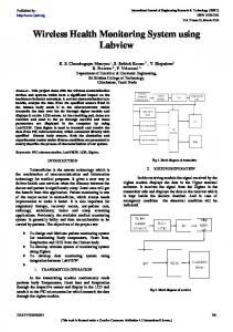
GUI build in VI shows the parameter values. Along with monitoring, the set point can also be assigned for alarming of the critical parameters. So the main Blocks for DAQ systems are: Input signals from Sensors
Controller GUI
Keywords- Microcontroller, Arduino-UNO, LABVIEW, DAQ System, Cost effective, Serial Communication
I. INTRODUCTION Fig.1 Basic Block Diagram of DAQ system
A. DAQ System: The field of data acquisition encompasses a very wide range of activities. At its simplest level, it involves reading electrical signals into a computer from some kind of sensor. These signals may represent the state of a physical process i.e. position and orientation of machine tools, furnace temperature, size and shape of a manufactured component etc. The acquired data may have to be stored, printed or displayed. Often the data have to be analyzed or processed in some way in order to generate further signals for controlling external equipment or for interfacing to other computers.[10] This may involve manipulating only static readings, but it is also frequently necessary to deal with time-varying signals as well. Some systems may involve data to be gathered slowly, over time spans of many days or weeks. Other will necessitate short bursts of very high speed data acquisition – perhaps at rates of up to several thousand readings per second. DAQ is used widely for laboratory automation, industrial monitoring and control, as well as in a variety of other time-critical applications. The most central reason for using the PC for data acquisition and control is that there is now a large and expanding pool of programmers, engineers and scientists who are familiar with the PC.[10] The data from the field is either digital or analog. Digital input is sampled continuously while the analog input is first converted into digital from using A/D converter. The microcontroller stores that value in its ROM. RAM is the data memory wherein the code resides. From the microcontroller, the data is transferred to LabVIEW by using VISA tool. The
Volume III Issue I
i.)
Input signals from Sensors: These signals are always in form of voltage or current. With help of calibration we can convert it in actual form.
ii.)
Controller: The controller will work as the communicator between real world and computer. According to the calibration factor of the sensors, the signal will get converted and we will get our actual output.
iii.) GUI: This is to display your calibrated signals on your software in PC or on LCD. B. Sensors: Sensors are the primary input element involved in reading physical quantities (such as temperature, force or position) into a DA&C system. They are generally used to measure analogue signals although the term „sensor‟ does in fact encompass some digital devices such as proximity switches. In this section we will deal only with sensing analogue signals. Analogue signals can be measured with sensors that generate either analogue or digital representations of the quantity to be measured.[10] Here in this system we are using three sensors which are useful almost in every industry. One is to measure Humidity and Temperature (DHT11), Second is an ultrasonic sensor (HC-SR-04) to measure distance. And third is LDR to measure light intensity.
IJRSI
ISSN 2321-2705
2nd International Conference on Multidisciplinary Research & Practice a)
which 6 can be used as PWM outputs), 6 analog inputs, a 16 MHz quartz crystal, a USB connection, a power jack, an ICSP header and a reset button. It contains everything needed to support the microcontroller; by connecting it to a computer with a USB cable or power it with a AC-toDC adapter or battery to get started. The code developing is too much easy for this microcontroller. Thus it has many benefits, user friendly approach, cost effective solution with accurate results.
DHT11 (Temperature and Humidity measurement): DHT11 Temperature & Humidity Sensor features a temperature & humidity sensor complex with a calibrated digital signal output. By using the exclusive digital-signal-acquisition technique and temperature & humidity sensing technology, it ensures high reliability and excellent long-term stability. This sensor includes a resistive-type humidity measurement component and an NTC temperature measurement component, and connects to a high-performance 8-bit microcontroller, offering excellent quality, fast response, anti-interference ability and cost-effectiveness. Communication Process: Single-bus data format is used for communication and synchronization between MCU and DHT11 sensor. One communication process is about 4ms. Data consists of decimal and integral parts. A complete data transmission is 40bit, and the sensor sends higher data bit first. b)
Ultrasonic HC-SR 04 (Distance measurement): Ultrasonic ranging module HC - SR04 provides 2cm - 400cm non-contact measurement function, the ranging accuracy can reach to 3mm. The modules includes ultrasonic transmitters, receiver and control circuit. The basic principle of work:
Using IO trigger for at least 10us high level signal The Module automatically sends eight 40 kHz and detect whether there is a pulse signal back. If the signal back, through high level, time of high output IO duration is the time from sending ultrasonic to returning. Calibration: Test distance = (high level time × velocity of sound (340M/S) / 2 c)
P a g e | 68
D.
LABVIEW:
LABVIEW (Laboratory Virtual Instrumentation Engineering Workbench) is nothing but software that provides virtual instrumentation. With help of LABVIEW here we are developing a graphical user interface to display the measured parameters. It has a block diagram coding so it is very easy to use and provides best solutions. II. BLOCK DIAGRAM AND DESCRIPTION The Block Diagram of the Low Cost Data Acquisition System is shown in the fig.2. In this system, three different sensors has been interfaced for monitoring four parameters i.e. Temperature, Level, Humidity and Light Intensity. DHT11 and Ultrasonic gives digital output while LDR gives analog output. The data from the sensor is taken to Arduino. The analog LDR output is converted to digital form. Arduino UNO has an in built A/D converter. The data received on serial monitor of Arduino is serially transmitted to LABVIEW with help of serial communication cable. The GUI is there build in LABVIEW. The serial data acquisition is done using the VISA tool. VISA is a protocol to provide communication between LABVIEW and any other device. Here the data is received serially at 9600 baud rate. The four different parameters i.e. Temperature, Level, Humidity and Light Intensity displays graphically on the front panel of LABVIEW. We can also provide a limitation to the parameters so that if the limit is crossed then, an LED glows for alarm purpose. This improves the safety of whole system where this DAQ system will get connected.
Light Dependent Resister: LDRs or Light Dependent Resistors are very useful especially in light/dark sensor circuits. Normally the resistance of an LDR is very high, sometimes as high as 1000 000 ohms, but when they are illuminated with light resistance drops dramatically.
C. Controller: Here in this system we are using Arduino Uno microcontroller. This board is based on the ATmega328P. It has 14 digital input/output pins (of
Volume III Issue I
Fig. 2 Block Diagram of our System
When we will power up the system (Vcc 5V) the very first thing we have to get done is burn the ARDUINO UNO with its code. On execution of the code, the values will get obtain
IJRSI
ISSN 2321-2705
2nd International Conference on Multidisciplinary Research & Practice on the serial monitor window in Arduino software. The total byte count will be depending on the string length. Now, this data will get transferred to LABVIEW by serial port. The data byte is first read by using VISA tool. The buffer gives the reading of all the sensors at once and will display the string in the Display Box.
P a g e | 69
The Actual Setup of our system is as shown in Fig. 4. The sensor will give the measured signal to the controller. The controller will calibrate the sensed data as per the calibration equation written in the code. And then by serial communication we will get the parameter values on the GUI of LABVIEW.
For data acquisition using serial interface, the important factor is the baud rate. The baud rate for this system is chosen as 9600 which the standard baud rate used. The VISA tool in LabVIEW requires the resource name which is for letting it known the actual source. This resource name is nothing the communication port of the laptop or PC. This can be known from the device manager. For set point allocation, the numeric value of each sensor is compared to some set point. This set value is compared with the process value, depending on the condition (TRUE/FALSE), the LED is made to glow. If the process value is more than the set value, alarming condition is established by making LED glow in RED color. For normal operations, the GREEN LED get glow.
Fig. 4 Experimental Setup (Hardware)
III. EXPERIMENTAL SETUP The Low Cost Data Acquisition System is tested with two parameters, Distance and Temperature. A.
In our system we measured the temperature with help of DHT11 sensor chip and validated the reading accuracy by comparing it with traditional methods. Here we are measuring the temperature with help of thermometer in traditional way. By doing this too, we are getting almost same results. (Including Human Errors for Measurement)
B.
Fig. 5 LabVIEW front panel GUI
Same way in our system we are measuring the Distance with help of ultrasonic sensor and validated it‟s reading by placing a wooden box in front of this sensor and getting the distance.
Here in fig. 5 LABVIEW GUI is shown. With help of this we can monitor the parameters easily.
Now in traditional way we are using the scale and measuring the distance between ultrasonic sensor and the wooden box. These results are also almost same. (Including Human Errors for Measurement)
In the above work, we had proposed a Low Cost DAQ system using Arduino-UNO controller and LabVIEW GUI. We can measure multiple parameters simultaneously and can monitoring the data with help of serial communication and Virtual Instrument LabVIEW software. The application of the above system was demonstrated by measuring multiple parameters simultaneously. The Features likes report generation, plotting, alarming was incorporated in the software and the data was received through serial communication in Personal computer.
IV. CONCLUSION
The proposed approach can be useful in the small process like level, temperature, Measurement at Gas station, Load Measurement with load cell at Way Bridge, and many small scale industries where cost effective solution is in need. Fig. 3 Comparison of Sensors with Traditional Measurement
Volume III Issue I
IJRSI
ISSN 2321-2705
2nd International Conference on Multidisciplinary Research & Practice
[4]. Manish Y. Upadhye, P. B. Borole, “Real-Time Wireless Vibration Monitoring System Using LabVIEW”, 2015 International Conference on Industrial Instrumentation and Control (ICIC) [5]. N.Mathivanan, PC-Based Instrumentation, PHI Publication. [6]. Mike Tooley, PC-Based Instrumentation and control, Newnes Publication [7]. Jovitha Jerome, Virtual Instrumentation using LabVIEW, PHI Publiction [8]. National Instrumentation, “www.ni.com”, Last access 30th October, 2015 [9]. Arduino UNO, “www.arduino.cc”, Last access 09th November, 2015 [10]. Kevin James, PC Interfacing and Data Acquisition: Techniques for Measurement [11]. Datasheet of Sensors, DHT11, HC-SR 04
ACKNOWLEDGEMENT The authors are thankful to Department of Instrumentation and Control, Dharmsinh Desai, India University to provide facilities. REFERENCES [1]. Dipika Kothari, Manish Thakker, V. A. Shah and Tushar Gohel, “A Real Time Wireless Multi –Parameter monitoring System with ZigBee and LabVIEW”, International Journal of Current Engineering and Technology, Vol.3, No.5 (December 2013) [2]. K P J Pradeep, K Sai Prasad Reddy, D Hanumesh Kumar, “Monitoring of Temperature and Humidity Using LIFA”, International Journal of IT, Engineering and Applied Sciences Research (IJIEASR), Volume 3, No. 6, June 2014 [3]. D. Calinoiu, R. Ionel, “Arduino and LabVIEW in EducationalRemote Monitoring Applications”
Volume III Issue I
P a g e | 70
***
IJRSI
ISSN 2321-2705