2014 Ist International Conference on Infonnation Technology, Computer and Electrical Engineering (ICITACEE)
Low Cost Implementation for Synchronization in Distributed Multi Antenna Using USRP/GNU-Radio Savitri Galih
Marc Hoffmann, Thomas Kaiser
Widyatama University Informatics Department Cikutra 204A, Bandung
[email protected]
Duisburg-Essen University Institute of Digital Signal Processing Bismarckstrasse 81, 47057 Duisburg
has an advantage in term of complexity and cost compare to the other measurement works in the references.
Abstract- Carrier Frequency Offset Synchronization is play a very important rule in the Distributed Multi antenna system, since the system has different individual clock instead of common
The organization of the paper is as follows : in first section is the introduction and back ground of the synchronization in thr distributed MIMO implementation. The second section is system overview followed by synchronization modul design and implementation using GNU Radio. Experiment set up end the experiment result is discussed in section 4 and finally we conclude the paper in section 5.
clock as in the centralized multi Antenna system. One of the established devices
is
synchronization methode for different transmitter Costas
Loop.
Some
implementation
of
the
synchronization for distributed multi antenna is discussed in some research works. In this paper we propose the low cost implementation of synchronization in distributed multi antenna and more simplified measurement method of synchronization in distributed multi antenna. The measurement result showed that the syncronization can compensate 0.5 kHz frequency offset
II.
experienced by the transmitters in the Distributed Multi antenna
In this work, we set up the system as shown on figure I. The system consist of one Master node that transmit reference signal to lock the Slave nodes and two slaves nodes that will be act as a transmitters for MIMO system that require precoding process. A Master node is set to the system, dedicated to synchronize all transmitters in a form of local master-slave arrangement. The master node transmit a reference unmodulated signal to the transmitters act as Slave nodes. The reference signal is used by the transmitters in order to estimate the frequency shift between the Slave node and the Master node
system.
Keywords- Synchronization,
USRP
I.
GNU Radio, Multi Antenna,
INTRODUCTION
Multi Antenna system or MIMO (Multiple Input Multiple Output) has demonstrated good performance for wireless system in term of data rate and spectral capacity. MIMO system can be implemented in a connected (centralized) or a distributed way. The main bottleneck for achieving the MIMO advantages in centralized MIMO is limited hardware, low scalability and multi user interference. Distributed multi user antenna is recommended as the answer of this problem, since it cooperate more than one antennas that separated spacely to build virtual MIMO system that more scalable, more interference manageable and more flexible to spread in more various space. However, since distributed MIMO consist of sparsely spaced different transmit devices that have their own individual clock without common clock to synchronize them, it is more challenging to find a synchronization scheme between transmitters in distributed MIMO.
•
There are some works for transmitter synchronization methods for distributed MIMO systems that implemented in testbed using GNU radio and USRP N210 platform [1,2] and WARP radio platform [3,4]
•
Fig. I. Distributed Multi Antenna with Master Node
Before transmitting to the receiver, the transmitter carry out the synchronization process using Costas Loop [8] that aimed for large scale MIMO system in this system.
In this paper we implement the costas loop [1] for synchronization using low cost Ettus USRP B-210 as a transmitters with less complex measurement scheme. We present the effect of the synchronization directly in the transmitter side without involving the receivers. This scheme
978-1-4799-6432-1114/$31.00 mOl41EEE
SYSTEM OVERVIEW
457
III.
SYNCHRONIZATION DESIGN AND IMPLEMENTATION USING
GNU RADIO We implemented the Synchronization module distributed MIMO using GNU-Radio framework. A.
GNU Radio
for
Overview
s(t)
GNU-Radio is a free and open software that provides signal processing blocks that can be utilized for RF real-time application. GNU-Radio is written in Python and C++ and run on most general purpose processors and mostly Linux operating system. The highest level of programming carry out in GNU-Radio is written in Python (i.e initialization and control for the signal processing component) , while the suppled, performance-critical signal processing path is implemented in C++. GNU-Radio also provides GNU-Radio Companion, a graphical user interface to create signal processing applications by drag-and-drop. To add new functional modul in GNU-Radio, we must write Python orland C++ code. The most basic concepts about GNU-Radio is flow graphs and blocks. Flow graph is a group of signal processing in GNU-Radio connected together to form a communication system. The GNU-Radio flow graphs are inizialized within the primary Python thread. Flow graph consist of several nodes called blocks. Any actual signal processing is done in the blocks, such as filtering, adding signals, transforming, decoding etc. Blocks are written in C++. To build distributed multi antenna system with synchronization, we need to extend GNU-Radio with the desired functions and blocks, i.e VCO etc.[5] B.
Fig. 2. Costas Loop
sr (t)
=
=
SQ (t)
=
=
Yr
Y-o
The synchronization process is carried out by costas loop [7]. This modul consists of two LPF, one VCO and three multiplier (figure 2.). The VCO perform as the heart of classic Costas Loop [7], i.e. to estimate the frequency offset between the transmitter's local oscillator and the reference signal from master node. The transmitters' frequency will be locked at the desired frequency since the loop make the offset smaller over time. The input to Costas Loop is the reference signal downconverted using the local carrier signal: =
m(t).cos(27ifJ
+ (ACt))
=
(A (t)
(I)
+
(3)
(t) .
(
and
¢i (t ))
m =--sm 9,(t)-9,(t) 2 ,
e(t)
(4)
)
(5)
from the difference of
¢i (t) that can be written as
mCt)
(6)
and VCO
will track the estimate value, adjust it and upconvert the signal
+
(
(
2
Narrow band LPF extract the DC value of
(
+ (t)).
as cos 27ifJ ¢i A flow graph for Synchronization for Distributed MIMO is shown in figure 1. The flow graph is for transmitters or slaves that need to be synchronized. It ia created using GNU Radio Companion (GRC). The Low Pass Filter is implemented by LPF module provided by GRC. An Automatic Gain level from AGC module in GRC also added to adjust the gain to a suitable level. Since the VCO isn't provided in GNU Radio source tree, we must extend GNU Radio with so called an out of-tree module or a new module. The preeminent tool that available to develop the new module is gr_modtool that
The input signal will be multiplied by the output of VCO, expJ 2JifJ+ i (t) . It splitted into : cos 2JifJ ¢Jt) and
¢ ) sin (2JifJ + ¢i (t) ) resulting :
m(t) COS 9 ( t ) i
e(t) = m:(t) COS(¢i(t)-¢i(t))sin(¢i(t)-¢i(t)) = m2(t)sin2(¢i(t)-¢i(t)) 8
between the i-th transmitter and master node.
(
=
We can obtain the error signal
where m(t) is sinusoidal reference signal,/c is carrier frequency of master node, (/J; 27ifJ [).(/J; is the frequency offset
(t)
+ 9i (t)). sin (2Jifct+ ¢i (t)) m�t) [sin (47ifct + 9 (t) + ¢ (t ))+ sin (9 (t) ¢ (t - i ))] i i i m(t). cos( 27ifJ
After passing the LPF the following is generated
Synchronization{or Distributed MIMO
set)
+ 9i(t))· cos (2Jifct + ¢i (t)) (2) met ) cos (4JifJ + 9;(t) + ¢;(t) )+ cOS (9; ( t ) - ¢;(t) )] [ 2
met ). cos( 2Jifct
)
458
FFT Plot
available in the GNU Radio source tree and is installed by default. First step is to create empty files for the block and edit the CMakelists.txt files. This job is done by gr_modtool on the command line with add command.
•
50 ,40· 30 -
- -----:-- - - - - � ------ f -
ClIO
10 -
,
I
,
I
I
I
I
I ,
I I
I ,
I I
I I
�
I I
:
" "
-:
,
I
I
I
I
I
"
----�--�--�__,
I
, I I I I I " ------:- - - - - - � ------� - - ----:------ �------ �-- - - - _L - -----:------ �------
20
� ] =a �
:------ � ----------:------ �- - - - - - f - -----------,
--
:- - - - - - � - ----- : ------: ---:------�------�------:-
: ;
�
----,------T
: ;
:
: ;
------- - - - - - � - - - - - - + - - ----- - - - - - - - - - - - - + - ------------- - - - - - + -----: : ' : : : : ----------- ------ ----------- _. ----- ---- - _L ------------ ------10 0
"
-
·20 .
I
I
:
: :
I I ,
I I T
I
: ..
-------: - - - - - � - ----- -------: ----I , ," "
·30
-- --
T
I I -,-
,
-
: ..
----- , ------ .... ------,1------ -----, , , , -,, ,, , ,
-----,,
- - -,- - - - - -,-
·40
"
, ,
. '________�__�__�______'1'__� 1. ________�__�_____' 50 40 20 ·50 ·40 ·30 ·20 ·10 30 50 10
Frequency (kHz) FFT Plot
•
50 ,---�--�----�
30 -
IV.
EXPERIMENT
I ,
! ] =a �
10 -
l»
0
-
,
I
I
I
I
I
I
I
I
,
,
,
,
,
,
,
,
:
"
---- - -:- - - - - - � - - - - - - � - - - - --:- - - - - - � - - - - - - � - - - - - -� - - - ---: - - - - - - � - ---- -
:
"
: :
"
- - - - -�-
: ---- -:- - - - - - � - ----- ;
-20' -3 0'
" "
:
---- - -- - - - - - � - - - - - - + - -- - --- - - - - - � - - - - - - f - -------- - ---- - - - - - f ----- : ' : " : "
:
-10
, ,
, , , �, - - - - - - �, - -- - --:-- - - - �, - - - - - - �, - - - - - -�, -- - ---:-----:
:
20
For creating the VCO block, we need to modify the three files (C++ implementation file, C++ implementation header file and C++ provided by gr_modtool from the previous command. The code for signal processing is added at the general_workO function In C++ implementation file. Equations.
" "
: - ---:----- - , ----- --- - -:- - - - - - � - - - - - - f - - - - --:---- - -" - -----, --------, , , , , , , , , , , , , , , , , , ---- - -:- - - - - - � - - - - - - � - -- - --:- - - - - - � - - - - - - � - - - - - -� -- - ---:- - - - - - � - ---- -
40· -
Fig. 3. Synchronization in Transmitter Flow Graph
, ,
--- - -:- - - - - - � - -----
"
:
- - - ------ - -
-
- - - ------ - -
I
I
, ,
, ,
, ,
·40
·30
·20
:
_ _ _ _ _L _ _
-
I
'
:
.,
I
·40· - --- -:- - - - - - � ------ f --
- - - - -�
.,
----- ------,...-- - ---,----- - ----- -
, ,
, , ,
, , , , , , , __ .�--� . --
, , , , , ,
, ,
, -----,------------------ ,-----, , , �.----� . --50 '_____�__�__�__�______"ll...._
SET UP AND RESULT
·50
For experiments, we used Ettus USRP N210 and USRP B210. Each USRP N210 consists of two main sub devices, amotherboard and different daughterboards which can transmit and/or receive different frequencyranges. We used SBX USRP daughterboards that provides up to 100mW output, 40 MHz ofbandwidth and has 400 MHz 4400 MHz frequency range with Gigabit Ethernet interface. USRPB210 is fully integrated single board USRP platform with frequency coverage from 70 MHz 6GHz and has USB 3.0 connectivity. The core component of each node is the PC which allocatesUSRPs as the baseband hardware, configures and controls the baseband hardware as well asRF front-end using the GNU Radio software. One PC is connected to both transmitters andreceivers to perform a feedback for antenna selection process in transmitters.
·10
10
20
---'
30
40
50
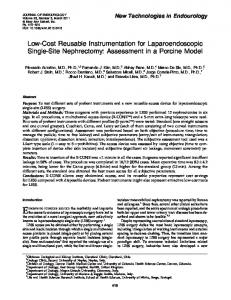
Frequency (kHz) Fig. 4. Frequency Spectrum of Unsynchronized Signal
We observed the received reference signal from master node and YCO output signal frequency with FFT Sink module for each slaves. Figure 4 presents the frequency spectrum of the unsynchronized received signal from master node at the two slaves nodes. Figure 5 and 6 shows the frequency spectrum of the received signal after being synchronized right before transmitted by the transmitters. FFT Plot out1 tr2
•
50 ,-
40 30 -
The measurementscenario set-up is carried out in an indoor environment to create the 3-user indoor interferencechannel. All nodes were equipped with three Log Periodic PCB Antenna that operates within 860MHz to 6.5 GHz frequency range. To conduct the measurement, master node transmitsto all slaves that simultaneously obtain the transmitted data. We used a N210 as a Master node and two B210 as a slaves or transmitters that need to be synchronized.
, ,
! ] =a �
10 -
&
0
-
" "
" "
: - - - - - + - - - - - � - - - - - - � - ---!-- - - - - � - - - - - - � ---- --� - - - - - + - - - - - � - --- ------:- - - - - - � - - - - - - + - - ---:- - - - - - � - - - - - - + -------: --- --:- - - - - - + ---- : : ' " .. -----: : -- --:- - - - - - � - --- : - ---:----, , , , I
I
I
I
I
I
I
I
--- - --:- - - - - - � - --- - - - - - ---:- - - - - - � - - - - -- : - - - - - -� - - - - --: - - - - - - � - -- - - -
- -
"
"
"
-
'
-
"
"
-
'
'
-10 -20' -30
" "
--- - --:- - - - - - � - - - - - - � - - - ---:- - - - - - � ------ �- - - - - -� --- - --:- - - - - - � - --- - I
20 -
--�--�----�
: --:- - - - - - � - - - - - - � - - - ---:- - - - - � - - - - - + - --------- --:------ � ----
-
-40'
-
-
--
--
I
I
I
,
,
,
-
I
-- ---,,---- - -,, ------,, - - - ---,------
- - - - - - +
- - - - -I- ______,______ + ______
I I I I , , , , ------T------,... ------,------.,---,
,
,
,
, , , , , , , , , , --- - --:- - - - - - � - - - - - - f - - - ---:----- - --- - --,------ --,,------,----,---, , , , , , , ,
. --� .--�.----� . -----' -50 '-----�--�--�--�------"----� -10 40 20 50 30 ·30 10 ·50 ·40 ·20
Frequency (kHz) Fig. 5. Frequency Spectrum of synchronized Signal for transmitter 2
459
FFT Plot out1
•
The measurement scheme exploits the measurement for each step in the main module (VCO). This method can reveal the function of the module clearly. Therefore, it is suitable for educational purpose in the wireless communications study and it can be implemented in the practical wireless communication lecture with fewer budget.
50 ,-
, ----- ------- , ,, ,, --: - - - - - � --- -- : - -- --:- - - - - - � - - - - - - � ------� ---20 - ---- ! 10 - ---- -; - - - - - � - - - - - - � - - ---; - - - - - � - - - - - - � ----- - � ---� 0 - ---- :- - - - - - � - - - - - - � - ----:- - - - - - � - - - - - - � - ------: ---: : : : : : �� - 10- ---- --- : --- -- : - -- ---; ; --- -- --- : ----- : ---- - - - - - � ------� ----20 - ---- ;- - - - - - � - - - - - - � - - ----;-30 -----:- - - - - - � - ----- ; - - ----:-- --- ----- ------ , ---,, -40 - ---- :- - - - - - � - - - - - - � - - - --:- - - - - - � - ----- : ---,, 40 -
-
30 -
-
,., - - - - - - 1 , , , ____ .J ______ .1 ______L ___
-
-
-
-
-
-
-
-
-
-
-
-
-
I
I
-
-
-
,
I
-
I
I
-
-
-
-
-
- - - - _.
I
I
I
I
I I
I I
I ,
I I
-
-
-
- "T
, ,
- - - - _.
-
I
-
- -
-
--�---.----.---,,--,
-
, ,
-:----- -- ---;-- ---:- - - - - - � -----: -;----- - --- .
-
- - - - - �
-
I
-
-
-
- l_
-
-:- - - - - - � - -----
-
References
-,------ .. ------
,, -:,,
-
-
- - - - -"i -
- -------�--�--''-
50 '20 40 30 -30 -50 -10 10 50 -40 -2 0
[I]
MM. Rahman, HE. Baidoo-Williams, R. Mudumbai and S Dasgupta, "Fully wireless implementation of Distributed Beamforming on a Software-defined radio platform," in Proceeding of the llih International Conference on Information Processing in Sensor Networks, Beijing, April 2012.
[2]
F. Quitin, MM. Rahman, R. Mudumbai and U. Madhow, "Distributed beamforming with software-defined radios: frequency synchronization and digital feedback" in Proceeding of Global Communications Conference (GLOBECOM), Anaheim, Dec. 2012.
[3]
HY. Balan, R. Rogalin, A Michaloliakos, K.Psounis, and G. Caire, "AirSync: Enabling Distributed Multiuser MIMO with Full Spatial Mutiplexing," IEEE/ACM Trans C. Pepin, and G. Eason, B. Noble, and I.N. Sneddon, "On certain integrals of Lipschitz-Hankel type involving products of Bessel functions," Phil. Trans. Roy. Soc. London, vol. A247, pp. 529-551, April 1955. (references)
[4]
R. Rogalin, O.Y. Bursalioglu, H.C. Papadopoulos, G. Caire, AF. Molisch, A Michaloliakos, HY. Balan, and K. Psounis, "Scalable Synchronization and Reciprocity Calibration for Distributed Multiuser MIMO", ;presented at IEEE Transactions on Wireless Communications, 2014, pp.1815-1831.
F requency (kHz) Fig. 6. Frequency Spectrum of synchronized Signal for transmitter I
This measurement results show that before the synchronization, there is 0.5 kHz frequency offset at each transmitter and the synchronization scheme compensate the offset and lock the frequency to the correct transmit frequency. v.
CONCLUSION
In this work we have implemented classic Costas Loop for distributed multi antenna system with simple measurement scheme. To the best of our knowledge, this is the low cost distributed multi antenna system implementation compare to previous works in the same topic. The transmitters also operate as a slave to the dedicated Master node. We use low cost USRP Ettus B-210 series and GNU Radio for the slaves/transmitters and USRP Ettus N-210 series as a master node. The measurement result show that the synchronization can compensate 0.5 kHz frequency offset at each transmitter.
[5]
What is GNU Radio : http://gnuradio.org/redmine/projects/gnuradio/wiki/WhatIsGR, 2014
460
[6]
T. M. Schmidl and D. C. Cox, "Robust frequency and timing synchronization for OFDM," IEEE Trans. on Commun.,vol. 45, no. 12, pp. 1613-1621, Dec. 1997
[7]
Z. Yang, Y. Bai, Z. Zhao, "Design and Implementation of the Digital Costas Loop Based on Software Defined Radio",; presented in 20ll International Conferernce on Instrumentation, Measurement, Computer, Communication and Control, Beijing, Chinna, 21 - 23 October 2011.