IEEE TRANSACTIONS ON CIRCUITS AND SYSTEMS—II: EXPRESS BRIEFS, VOL. 54, NO. 6, JUNE 2007
507
A Low-Cost VLC Implementation for MPEG-4 Pei-Yin Chen and Yi-Ming Lin
Abstract—In this brief, a low-cost technique to implement variable-length coding (VLC) is presented. Instead of using a large codeword table as with most traditional methods, we employ two smaller tables, symbol-address table and section-based table, to encode input symbols. Compared with previous methods, our VLC implementation can reduce about 17% to 38% of memory space for storing larger VLC tables in MPEG-4 application. Synthesis results show that the proposed VLC encoder and decoder occupy 19761 and 20187 gate counts, respectively. Index Terms—Lossless compression, low cost, MPEG-4, variable-length coding (VLC).
I. INTRODUCTION
T
HE fundamental characteristics of a multimedia system are that they incorporate continuous media such as voices, full-motion videos, and graphic images. Since the representation of audio, video, and image involves a vast amount of data, so the need for compression becomes indispensable. Recently, many advanced technologies for data compression have been presented. A good compression method needs to consider four issues: coding efficiency, computing complexity, coding delay, and signal quality. Variable-length coding (VLC) such as Huffman coding [1] is a very popular method and usually employed within the framework of lossless compression. By assigning shorter codewords to frequently occurring symbols and longer codewords to infrequently occurring symbols, VLC can remove data redundancy efficiently. Nowadays, VLC has been adopted by various compression standards such as JPEG, MPEG-1, MPEG-2 [2], H.263 [3], and MPEG-4 [4]–[6]. VLC can be implemented with traditional look-up table (LUT) technique. However, the cost of LUT implementation becomes too high and unacceptable when the VLC codeword table is large, such as Table 14 for discrete cosine transform (DCT) coefficients in MPEG-2 and Table 96 for TCOEF in MPEG-4. In the past decade, many useful techniques for VLC VLSI realization were proposed in the literature [7]–[12]. Most of them [8]–[11] focused on memory reduction for larger codeword tables to reduce hardware cost. Mukherjee et al. presented a RAM-based VLC codec architecture [8] to save memory space and obtain table programmability by changing memory contents. In [9], Fukuzawa et al. developed a VLC core for MPEG-1/2 and H.261. Shieh et al. [10] proposed a new approach of group-based VLC codec system. Their design Manuscript received November 23, 2005; revised June 23, 2006, and September 29, 2006. This work was supported in part by the National Science Council, R.O.C, under Grant NSC-95-2221-E-006-504. This paper was recommended by Associate Editor T. Stouraitis. The authors are with the Digital IC Design Laboratory, Department of Computer Science and Information Engineering, National Cheng Kung University, Tainan 701, Taiwan, R.O.C. (e-mail:
[email protected]; ymlin@csie. ncku.edu.tw). Digital Object Identifier 10.1109/TCSII.2007.891752
uses codeword grouping and symbol memory mapping for encoding/decoding VLC. Higgie and Fong [11] presented a series of efficient and simple algorithms for VLC encoding and decoding based on a pointer look-up approach. It would be nice to have a memory-efficient technique to reduce the cost of VLC implementation. In this brief, we present a low-cost technique for VLC VLSI implementation. Two smaller tables, symbol-address table and section-based table, are employed in place of a large codeword table. The symbol-address table contains the addresses of all possible input symbols. All symbols’ codewords are separated into different classes and sections, and only the most representative codeword in each section is stored into the section-based table to reduce the required storage space. As compared with other VLC techniques for MPEG-4 application, our design reduces about 17% to 38% of memory space for larger VLC tables. In the simulation, we demonstrate that our design can reduce about 17% of gate count compared with the LUT technique. Hence, it is a good candidate for low-cost VLC implementation. The rest of this brief is organized as follows. In Section II, the proposed technique for VLC implementation is introduced in detail. The comparisons of various VLC implementations are described in Section III. Sections IV and V describe the VLSI architecture and chip implementation of our VLC. The conclusion is provided in Section VI. II. PROPOSED TECHNIQUE FOR VLC IMPLEMENTATION The VLC is a very popular lossless compression method. In this section, we will introduce the basic concepts of VLC first. Then, the pre-processing and encoding/decoding procedures of our technique will be described in details. A. Basic Concepts for VLC The main principle of VLC is that it uses a lower number of bits to encode symbols that occur more frequently. Since VLC can reduce the redundant data and achieve an excellent coding efficiency, it has been adopted by many compression standards [2]–[4]. However, the challenge of VLC is that the codeword lengths are variable. The encoded result is a bitstream without direct codeword boundaries, so it is difficult to decide the codeword length to extract codeword, and to align the bitstream for decoding. Besides, variable-length codewords cannot be stored directly with hardware when VLSI realization is considered. Memory is the most popular hardware storage for storing data. The bit width of each entry in a memory is the same, but codewords of VLC are not. Obviously, some modifications must be done to store variable-length codewords into memory. Traditionally, VLC is implemented with LUT and bit-stuffing techniques directly. By stuffing extra bits into codewords, we can equalize the lengths of all codewords. The stuffed
1549-7747/$25.00 © 2007 IEEE
508
IEEE TRANSACTIONS ON CIRCUITS AND SYSTEMS—II: EXPRESS BRIEFS, VOL. 54, NO. 6, JUNE 2007
Fig. 1. VLC example. (a) VLC codeword table. (b) Memory implementation for VLC codeword table.
codewords, also named as constant-width pseudocodewords (CWPCs), have identical bit widths and can be stored easily in a proper memory space. Fig. 1 shows an example of the VLC codeword table, and its memory implementation. To perform decoding procedure correctly, we must save the valid bit width of each codeword. Since the valid bit width is between 2 to 4 in this example, we have to store 2 bits for each codeword. Besides, each codeword is stuffed with bits “0” to obtain its CWPC. Thus, the size of required memory, as shadowed in bits for direct LUT Fig. 1, is a total of implementation of this example. B. Pre-Processing Procedure In our method, the VLC encoding/decoding procedure is achieved by using the hardwired circuit and two tables, symbol-address table and section-based table. The symbol-address table contains the new addresses of symbols. All symbols’ codewords are separated into different classes and sections, and only the most representative codeword in each section is stored into the section-based table to reduce the required storage space. Instead of using a large codeword table as with traditional LUT method, our design employs these two smaller tables and a hardwired circuit which will be mentioned later in Section IV-B to perform coding. The detailed steps of constructing the two tables before coding are described in the following. Steps for Constructing the Symbol-Address Table The symbol-address table is constructed as follows. Step 1) Generate CWPC of all symbols by stuffing necessary “0” bits. Step 2) Sort all symbols’ CWPC. Step 3) Decide the new address (or location) of each symbol by using the sorted CWPC. Step 4) Store all symbols’ new addresses into the symboladdress table. Using the sorted CWPC generated after Step 2, we can allocate symbols easily into different classes and sections which will be discussed later. Besides, symbol order of the sequence from , to is changed after Step 2, so we need to store the new address of each symbol into the symbol-address table when
Fig. 2. Construction of symbol-address table. (a) CWPC table. (b) New addresses of all symbols. (c) Memory implementation for symbol-address table.
Fig. 3. Construction of section-based table. (a) All symbols’ contents and section representatives. (b) Memory implementation for section-based table.
real implementation is considered. Fig. 2 shows construction of symbol-address table for previous example where the required memory for symbol-address table is shadowed. Steps for Constructing the Section-Based Table The section-based table is constructed as follows. Step 1) Find the minimum of all symbols’ valid bit widths, denoted as , and then assign the -bit prefix of each symbol’s codeword as its corresponding class. Step 2) Allocate symbols with the identical valid bit width and continuous codewords in the same class to one section. Step 3) Choose one symbol for each section which owns the minimum symbol address as the section’s representative. Step 4) Store the CWPC, valid bit width and symbol address of all representatives into the section-based table. After Steps 1 and 2, we can allocate symbols whose CWPC are highly correlated into the same section. Then, only the contents of the most representative symbol (CWPC, valid bit width and symbol address) must be saved for each section. By using the section representative, we can calculate other symbols’ contents easily in the same section. Fig. 3 shows construction of section-based table for previous example. The minimum of all symbols’ valid bit widths, , is 2, thus all symbols are separated into four classes: 00, 01, 10, and 11. Finally, five symbols (A, E, B, C, and H) are chosen as section representatives, and the related contents are stored. Observably, the least significant bit (LSB) of all five representatives is the same, so we can omit
CHEN AND LIN: A LOW-COST VLC IMPLEMENTATION FOR MPEG-4
the storage of this bit by adding hardware stuffing wire. The required memory for section-based table is shadowed in Fig. 3.
509
TABLE I REQUIRED BITS FOR STORING VLC MPEG-4
C. Proposed Encoding/Decoding Procedure In our method, the VLC encoding/decoding procedure is achieved by using the hardwired circuit and two tables generated in pre-processing procedure. The steps of encoding and decoding procedures are described in detail as follows. Encoding Procedure Step 1) Input the symbol to be encoded, denoted as . Step 2) Get the address of symbol (denoted as ) from the symbol-address memory. Step 3) Determine the section that symbol belongs to (de, and obtain the correnoted as ) by using sponding CWPC, valid bit width and symbol ad(denoted as ) dress of the representative in from the section-based memory. and the Step 4) Calculate the difference value between symbol address of . Step 5) Calculate the offset value by shifting the difference value left with bits where is obtained by subfrom the bit width tracting the valid bit width of of CWPC. Step 6) Calculate the sum value by adding the offset value and the CWPC of . Step 7) Determine the encoded result of symbol by picking prefix bits from the sum value where is the valid bit width of . At Step 3, we use a hardwired mapping module to determine by using . Assuming that the symbol to be encoded is “ ” and that previous codeword example is adopted, the practical encoding procedure for our method can be described as follows. “ .” 1) according to Fig. 2. 2) 3) and “ ” according to Fig. 3. —symbol address of “ ” 4) Different value . the bit width of CWPC—the valid bit width of “ ” 5) , and offset value bit . of “ ” 6) Sum value . and the encoded result . 7) Decoding Procedure Step 1) Get bits from the bitstream waiting to be decoded where is the bit width of CWPC, and put them into the register . Step 2) Determine the section that belongs to (denoted as ), and get the corresponding CWPC, valid bit width and symbol address of the representative in (denoted as ) from the section-based memory. Step 3) Calculate the offset value by subtracting the CWPC from . of Step 4) Calculate the different value by shifting the offset value right with bits where is obtained by subtracting the valid bit width of from the bit width of CWPC. Step 5) Calculate the sum value by adding the different value and the symbol address of .
Step 6) Determine the decoded symbol whose address is equal to sum from the symbol-address memory. At Step 2, we use a hardwired mapping module to determine by using . Assuming that the bitstream to be decoded is “011110” and that previous codeword example is adopted, the practical decoding procedure for our method can be described as follows. ” and “ .” 1) Bitstream “ 2) and “ ” according to Fig. 3. of “ ” 3) Offset value . the bit width of CWPC—the valid bit width of “ ” 4) , and different value bit . symbol address of “ ” 5) Sum value . 6) The decoded symbol “ .” III. COMPARISONS For comparison, we implemented the proposed VLC technique for MPEG-4 simple profile [4]. In the standard, header (MCBPC and CBPY), motion vector (MVD), and quantized transform coefficient (INTRADC and TCOEF) are needed to be encoded with the corresponding VLC tables. Table I shows the required bits for storing each VLC table. In Table I, Table 79, Table 96, and Table 97 are larger and have more influence on hardware cost of MPEG-4, so we focus on the comparisons of them for various VLC implementations. Other smaller VLC tables have less influence on hardware cost and can be realized with LUT implementation or the dedicated circuits easily, so we skip their comparisons. Table 79 is used to encode MVD (see Table I). It contains 65 input symbols. Traditional LUT technique requires 13 bits to store CWPC and 4 bits to store the valid bit width, so the rebits. quired memory space for Table 79 is Table 96 and 97 are used to encode intra TCOEF and inter TCOEF, respectively. A total of 102 input symbols are needed to encode intra TCOEF where the bit widths of codewords are from 2 to 12 bits without sign bit. Hence, the LUT technique requires 12 bits to store CWPC and 4 bits to store the valid bit width, and the size of required memory for Table 96 is bits. In fact, the contents of Table 96 and 97 are the same
510
IEEE TRANSACTIONS ON CIRCUITS AND SYSTEMS—II: EXPRESS BRIEFS, VOL. 54, NO. 6, JUNE 2007
TABLE II COMPARISONS OF MEMORY SPACES NEEDED FOR VARIOUS METHODS
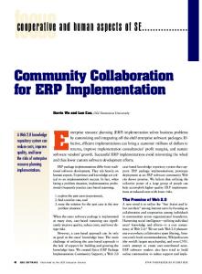
Fig. 4. VLSI architecture of our MPEG-4 VLC encoder.
according to the standard, so we need to keep one memory only for real implementation. Thus, the required memory space is bits for LUT implementation. In the proposed MVD VLC implementation, the symbol-adbits since we need 7 bits to dress memory is distinguish 65 symbol addresses. Besides, we allocate the codewords for encoding MVD into ten different sections, so the size bits where of section-based memory is 13, 4, and 7 bits are used to represent each section representative’s CWPC, valid bit width and symbol address, respectively. In our TCOEF implementation, the symbol-address memory is bits since we need 7 bits to distinguish 102 symbol addresses. The three bits to the far right (less significant three bits) of CWPC are all 0’s, hence we can omit the storage of those bits by adding hardware stuffing wires. Besides, we allocate the codewords of VLC tables for TCOEF into 15 different sections, so the size of section-based memory is bits where 9, 4, and 7 bits are used to represent each section representative’s CWPC, valid bit width and symbol address, respectively. Similarly, the memory required for VLC decoder can be constructed easily. Table II shows the memory spaces of the MVD and TCOEF needed for our VLC implementation, the LUT implementation and others [8]–[11]. Evidently the required memory spaces of our method are less than those of others. It achieves a memory reduction of about 17% to 38%. Compared with traditional LUT technique, our design and previous VLC implementations [8]–[11] obtain the advantage of less memory with the sacrifice of extra hardware circuit for the mapping and codeword generating units. In Section V, we will demonstrate that the cost of the reduced memory is higher than the cost of extra hardware in real implementation. IV. VLSI ARCHITECTURE FOR OUR VLC The block diagram of VLSI architecture for our MPEG-4 VLC encoder is shown in Fig. 4. It consists of the input buffer, EN_M, EN_C, EN_MV, EN_I, EN_T, the multiplexer, the packer, and the controller. The input buffer registers the input data for the following five encoders. The EN_M, EN_C and EN_I are direct hardwired circuits used to encode the MCBPC, CBPY and INTRADC, respectively. Two encoding modules, EN_MV and EN_T, are used to encode the MVD and TCOEF, respectively, and both are implemented by using the proposed VLC technique. Each of EN_MV and EN_T is composed of the
Fig. 5. Encoding module for EN_MV/EN_T.
mapping unit (MU), the codeword generating unit (CGU) and two memories (SA and SB), as shown in Fig. 5, to carry out one VLC table for the MVD or TCOEF defined in MPEG-4. The details of them are described in Sections IV-A–D. The multiplexer is used to generate the encoded results in the required order. The function of packer is to accumulate continuously the encoded results, and to enable the ready signal when every 32-bit encoded output is ready. The controller, realized with a finite-state machine (FSM), monitors the data flow and sends proper control signals to all other components. Similarly, the MPEG-4 VLC decoder can be implemented easily by reversing the encoding process. A. Memories Two memories are used to store the symbol-address table and section-based table, respectively. The memory for symbol-address table, denoted as SA memory, stores all symbols’ new addresses. The memory for section-based table, denoted as SB memory, stores the CWPC, valid bit width and symbol address of all representatives. B. MU and CGU The MU is a hardwired circuit which uses the new address of currently input symbol as inputs, determines the secto which symbol belongs, and finally outputs the cortion responding address of section representative . The address of is used to obtain its CWPC, valid bit width and symbol address from SB memory. In other words, the MU performs Step 3 of our encoding procedure described in previous section. The CGU performs Steps 4 to 6 of the encoding procedure and finally outputs the sum value for symbol . It consists of one adder, two subtractors, one barrel shifter, and three registers. The upper subtractor calculates the difference value between and the symbol address of . The lower subtractor calculates by subtracting the valid bit width of from the bit width of CWPC. The shifter generates the offset value by shifting the difference value left with bits. The adder produces the sum value by adding the offset value and CWPC of . The three registers are used for the purpose of pipelining.
CHEN AND LIN: A LOW-COST VLC IMPLEMENTATION FOR MPEG-4
C. Packer The function of packer is to continuously accumulate input symbols’ sum values, and to enable the ready signal when each 32-bit encoded output is ready. It consists of two barrel shifters, three registers, and one accumulator. Here, the sign bit is inserted into the encoded result according to MPEG-4 VLC. The left barrel shifter produces the encoded codeword for each input symbol by picking prefix bits from the sum value where is , and then concatenates the encoded the valid bit width of result. The right barrel shifter segments the encoded result into stores the previously 32-bit words for output. The register concatenated codeword bits which have not yet been output, and stores the 32-bit output word. The 5-bit accumuthe register lator accumulates the valid bit widths, and generates the carry out (as soon as the sum of valid bit widths is larger than 32) to form the output-available signal ready of the packer. D. Control Unit The control unit, realized with FSM, monitors the data flow and sends proper control signals to all other components. Two input signals start and reset, as shown in Fig. 4, are used to set up the working mode of our design. When the reset signal is set to be high, the design clears all register data. When the reset signal is set to be low, bringing the start signal to high will activate the design to encode input symbols in sequence. V. CHIP IMPLEMENTATION AND PERFORMANCE The VLSI architectures of our VLC encoder and decoder were implemented by using Verilog HDL where the memories of the MVD and TCOEF were generated by using Artisan TSMC’s 0.18- m memory compiler. We used Synopsys Design Compiler to synthesize the design with the standard cell from Artisan TSMC’s0.18- m cell library. The layout for the design was generated with Astro (for placement and routing), and verified by Mentor Calibre (for DRC and LVS checks). Since previous VLC techniques [8]–[11] are not designed specially for MPEG-4, it is not easy to compare the hardware cost of our VLSI implementation with theirs directly. However, we have implemented the MPEG-4 VLC encoder and decoder with traditional LUT technique for comparison. Table III lists the features of the proposed VLC and the LUT VLC for MPEG-4, respectively, where all MPEG-4 VLC tables as shown in Table I are implemented. Compared with the LUT technique, our design obtains the advantage of less memory with the sacrifice of extra hardware. Hence, our VLC needs less gate count for memory, but more for the dedicated coding circuits. However, the gate counts, shown in the “Total” column of Table III, demonstrate that the cost of the reduced memory is higher than the cost of extra hardware for our VLC implementation. Evidently, our encoder and decoder can reduce about 16% and 18% of gate count, respectively. Hence, our design is a good candidate for low-cost VLC implementation.
511
TABLE III FEATURES OF TWO MPEG-4 VLC ENCODERS AND DECODERS
VI. CONCLUSION VLC is a very important and popular lossless encoding method, and adopted by most image/video coding standards. In this brief, we present a new technique for VLC VLSI realization. Compared with previous methods, our design requires the least memory space. In the simulation, our design works with a clock rate of 200 MHz and can support video resolution of VGA at 30 fps in real time. Our future work will be focused on the VLC implementation of H.264 standard. ACKNOWLEDGMENT The authors wish to thank the Ministry of Education, Taiwan, R.O.C., for the use of Shared Facilities supported by the Program of Top 100 Universities Advancement, Ministry of Education, Taiwan, R.O.C. REFERENCES [1] D. A. Huffman, “A method for the construction of minimum redundancy codes,” Proc. IRE, vol. 40, pp. 1098–1101, Sep. 1952. [2] Generic coding of moving pictures and associated audio: Systems, ISO/IEC JTC1/SC29/ WG11 N0801, Nov. 13, 1994. [3] Video Coding for Low Bit Rate Communication, ITU-T Rec. H.263, Jan. 27, 1998. [4] Coding of Moving Pictures and Audio: MPEG-4 Video Verification Model Version 18.0, ISO/IEC JTC1/SC29/WG11 N3908, Jan. 15, 2001. [5] S. Y. Yap and J. V. McCanny, “A VLSI architecture for variable block size video motion estimation,” IEEE Trans. Circuits Syst. II, Exp. Briefs, vol. 51, no. 7, pp. 384–389, Jul. 2004. [6] H. W. Cheng and L. R. Doug, “A content-based methodology for power-aware motion estimation architecture,” IEEE Trans. Circuits Syst. II, Exp. Briefs, vol. 52, no. 10, pp. 631–635, Oct. 2005. [7] A. Mukherjee, N. Ranganathan, and M. Bassiouni, “Efficient VLSI designs for data transformation of tree-based codes,” IEEE Trans. Circuits Syst, vol. 38, pp. 306–314, Mar. 1991. [8] A. Mukherjee, N. Ranganathan, J. Flieder, and T. Acharya, “MARVLE: A VLSI chip for data compression using tree-based codes,” IEEE Trans. VLSI Syst., vol. 1, no. 2, pp. 203–214, Jun. 1993. [9] Y. Fukuzawa, K. Hasegawa, H. Hanaki, E. Iwata, and T. Yamazaki, “A programmable VLC core architecture for video compression DSP,” in Proc. IEEE SiPS’97 Design and Implementation, Nov. 1997, vol. 3, pp. 469–478. [10] B. J. Shieh, Y. S. Lee, and C. Y. Lee, “A new approach of groupbased VLC codec system with full table programmability,” IEEE Trans. Circuits Syst. Video Technol., vol. 11, no. 2, pp. 210–221, Feb. 2001. [11] G. R. Higgle and A. C. M. Fong, “Efficient encoding and decoding algorithms for variable-length entropy codes,” Proc. IEE Commun., vol. 150, pp. 305–311, Oct. 2003. [12] S. W. Lee and I. C. Park, “A low-power variable length decoder for MPEG-2 based on successive decoding of short codewords,” IEEE Trans. Circuits Syst. II, Analog Digit. Signal Process., vol. 50, no. 2, pp. 73–82, Feb. 2003.