Low Cost PWM Converterfor Utility Interface of Variable Speed Wind Turbine Generators Ali M. El-Tamaly*
H. H. El-Tamaly**
*Power Quality Laboratory Electrical Engineering Dept. Texas A&M University Collage Station, TX. 77843-3 128 Te1.(409)845-7466 Fax: (409) 845-6259 E-mail:
[email protected]
E. Cengelci
**Electrical Engineering Dept. Faculty of Engineering Elminia University, Elminia, Egypt Tel. 2-086-322083 Fax: 2-086-342601 E-mail: rumenia@,rusys.eg.net
-
P. N. Enjeti*
E. Muljadi***
***National Renewable Energy Laboratory 1617 Cole Boulevard Golden, Colorado 80401 Tel: (303) 384-6904 Fax: (303) 384-6901 E-mail: eduard
[email protected]
To interface a VSCF WTGs to electric utility, a power converter is required. The power converters must be controlled to give a constant voltage, constant frequency output at the utility side. In addition, it should be low cost and reliable to minimize the cost of energy. The aerodynamic power from the wind is converted to mechanical power. The power from the wind turbine is transferred to AC generator via gearbox to increase the shaft speed. Some turbines use direct-drive concept where the turbine is directly connected to a generator. The output of AC generator is connected to electric utility via power conditioner (power converter). The output power of the generator (which is in the form of variable frequency AC) must be transferred to the utility at constant frequency, constant voltage and good power quality
Abstract In this paper a low cost PWM converter for a variable speed Wind Turbine Generator (WTG) is descussed. A six-switch PWM converter is utilized to convert a three-phase power from a WTG to a singlephase electric utility. The proposed converter consists of two stages. The first stage is a variable frequency PWM converter with 4-IGBT's to control the output power of the generator. The second stage employs 2-IGBT's to return the power to the electric utility. These two stages have common DC-link. The utility output current is sinusoidal with a good quality. Suitable PWM control via Space Vector Modulation is designed to control the generator. And current regulated PWM is used to control the utility side. Results from the simulation of the power converter are presented in this paper. The proposed converter is suitable for utility interface of WTGs up to 20 kW ratings I-Introduction Wind energy conversion is a very mature technology after many years of development. Its applications are widely accepted all over the world. The wind power has a huge potential to supply electrical power without generating pollution. It has the potential to provide many countries with one-fourth or more of their electricity demand. There are two major types of operation to generate the electricity using WTGs. The first one is called constant-speed constantfrequency (CSCF) operation and second one is variable-speed constant-frequency (VSCF) operation. Most of the new WTGs are designed for VSCF operation. The VSCF operation has many potential benefits over CSCF operation such as (1) It generates more energy by operating at higher turbine efficiency. (2) The cost per k W h is lower. (3) It reduces stresses in the drive train due to flywheel effect of the rotor. (4) It minimizes the audible noise when operating in light winds. ( 5 ) It simplifies the mechanical design.
0-7803-5160-6/99/$10.00 0 1999 IEEE.
*
I
,
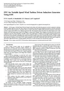
Fig. 1 The bonventional method to interface three phase WTG bith single phase electric utility
11-Proposed System The existing configuration for the converter as shown in Fig.1, uses six switches (Six switch Topology, SST) at the generator side and four switches at the utility side, a total of ten. Fig.2.shows the proposed six-switch P W M converter with four switches (Four Switch Topology, FST) at generator side and two switches at the utility side. Then, four switches in SST are replaced with only one capacitor at DC link. It is apparent that the cost and reliability are two major advantages of the proposed converter. The cost reduction can be accomplished by reducing the number of switches and by reducing the complexity of control system. Space Vector Modulation (SVM) technique is chosen as the algorithm to control the generator. At the utility interface, the current
889
voltage from AC generator and A’, B’ and C’ are corresponding to the terminal voltage of AC generator. The line voltages at the terminals of AC generator (A’, B’ and C’) expressed in terms of variables S1 and S2 as follows
regulated PWM converter gives a good power quality (it can easily achieve the requirements of IEEE 519-1992 [I]). The power can flow in both directions and the output power at the utility can be adjusted to produce or to absorb reactive power (leading or lagging power factor). Thus the generator can function as a motor to start the wind turbine and the utility side can function as a reactive power compensator at light load. Vd = 2 VL-LI moi (1)
Vd Vd Vd VIE = s, - s, = (2s1- 1)2 2 2
And,
v. 2
(2)
vel,= SI - s, VJ = (2s1- 1)- V d 2
(3)
2
From equation (2) and (3), it can be found that I
VeaA,= v,,,, - v,.,, = (SI - S 1 ) v d
Constant Frequency PWM
IG ,Variable frequency PWM
W G
I ~ c ~ i nI Converter k I
Converlcr
The SVM is better understood if the line quantities are transferred into the a p form. By taking mid point of DC bus as a reference, let Vmp= A VAoBT# (4) Where
Wind
r
I
I
1
1
I
Fig2 Proposed converter 1
The main shortcoming with this topology (FST, Fig.2) is that the DC link voltage must be at least twice the maximum line to line input voltage as shown in (1). The topology in Fig,.2 is suitable for lower utility voltage (230V). Another Variation of the converter is shown in Fig.3. This topology is suitable for higher utility voltage (460V). However, the induction motodgenerator needs to be lower voltage (230V). Since standard induction motodgenerator are available in dual voltage (460/230V) the induction generator connection can be altered and topology in Fig.3 can be employed. Constant ... ~
IG
V
‘able frequency P anvcnsr
W DC Link I
I
~
~
FrequencyPWM Converter I
Applying (2), (3) into (4), we get (5)
And, Vp =
VI I
I
1
(6)
The combination of states of switches (S1-S4) produce four different vectors in the a p plane as shown in Table (1). These vectors are shifted of d 2 from each other as shown in Fig.4. From this figure, we can see that, the vectors V, and V, are opposite directions and they have equal amplitude. The amplitude is 6 times the amplitude of 5 and V3 . Similarly, vectors VI and VI are opposite direction and equal in magnitude.
Vap I
$(s3- i) vd
SI S3 0 0
va -- vd 2fi
I
Fig.3 Proposed converter2
111-System Analysis In this study Space Vector Modulation, (SVM) for Fig.2 is discussed. In Fig.2 let us assume the conduction state of power switches be associated to the binary variables SIto s6. The binary “1” indicates a closed switch and “0” an open one. The switches (SI, S2), (S3, S4) and ( S S , s6) are complementary and as consequence, &=I- S2, S3=1- S4 and S5=l- s6. The points A, B and C correspond to the terminal of generated
890
VP
Vap=Va+jVp
vd
.2fi
- e
Jz
.2n J-
vb
If t1-t3>0,then tl= tl-t3 (16) Or If t1-t3