Le codage du signal de parole de qualitd "network?' a fait rdcemment l'objet ... deurs serait une bonne suggestion pour abaisser le d6bit sous le seuil de 16 ...... In the experiments, to "cure" the "physical" and "numerical" ill-conditioning, the.
Low-Delay Speech Coding at 16 kb/s and Below
Majid Foodeei
B. Eng.
A thesis submitted to the Faculty of Graduate Studies and Research in partial fulfillment of the requirements for the degree of Master of Engineering
Department of Electrical Engineering . . McGill University Montrhal, Canada May, 1991
@ Majid Foodeei, 1991
Abstract Development of network quality speech coders at 16 kb/s and below is an active research area. This thesis focuses on the study of low-delay Code Excited Linear Predictive (CELP) and tree coders. A 16 kb/s stochastic tree coder based on the (M,L) search algorithm suggested by Iyengar and Kabal and a low-delay CELP coder proposed by AT&T (CCITT 16 kb/s standardization candidate) are examined. The first goal is to compare and study the performance of the two coders. Second objective is to analyze the particular characteristics which make the two coders different from one another. The final goal is the improvement of the performance of the coders, particularly with a view of bringing down the bit rate below 16 kb/s. When compared under similar conditions, the two coders showed comparable performance at 16 kb/s. The analysis of the components and particular characteristics of the tree and CELP coders provide new insight for future coders. Higher performance coder components such as prediction, gain adaptation, and residual signal quantization are needed. Issues in backward adaptive linear prediction analysis for both near and far-sample redundancy removal such as analysis methods, windowing, ill-conditioning, quantization noise effects and computational complexities are studied. Several new backward adaptive high-order methods show much better prediction gains than the previously reported ones. Other than a better high-order predictor for both coders, other suggestions to improve the performance of the coders include a new scheme of training of the excitation dictionary and better gain adaptation strategy for the tree coder. A hybrid "Tree-CELP" coder, taking the best components from the two archetypes is a good candidate to push coding rates below 16 kb/s.
Sommaire Le codage du signal de parole de qualitd "network?' a fait rdcemment l'objet d'un effort de recherche considdrable portant sur le diveloppement de codeurs faible ddlai B 16 kb/s et moins. Ce mbmoire traite du codage par "Code Excited Linear Predictive" (CELP) et du codage arborescent B faible ddlai. Un codeur arborescent bas6 sur l'algorithme de recherche (M,L) de Iyengar et Kabal et un codeur CELP & faible ddlai propos6 par AT&T (candidat pour la standardisation & 16 kb/s au CCITT) sont utilis6s. Nous poursuivons trois objectifs. Le premier est de comparer la performance des deux codeurs. Le second est d'analyser les caractdristiques qui les distinguent. Le but final est l'amdlioration de la performance des codeurs, et en particulier, d'abaisser le dibit sous le seuil de 16 kb/s. Les deu:: codeu2s donnent, dans les m6mes conditions, des performances sirnilaires B 16 kb/s. L'analyse des composantes et des caractdristiques spdcifiques aux codeurs arborescent et CELP facilitera le ddveloppement de nouveaux codeurs. Des 6liments plus performants du codeur (pridiction, adaptation du gain, et quantification du signal rdsiduel) sont ndcessaires. Plusieurs aspects de la prddiction linCaire par adaptation causale visant 1'Climination des redondances sont 6tudiks: les mithodes d'analyse, le fenetrage, le conditionnement, l'effet du bruit de quantification et la complexitd des calculs. Plusieurs nouvelles mdthodes causales d'ordre dlevd presentent un gain de pridiction supirieur & celui obtenu avec les mithodes connues. L'amdlioration du prddicteur n'est pas la seule suggestion: une nouvelle mdthode d'entrainement du dictionnaire "d'excitation" et une meilleure stratkgie d'adaptation du gain pour le codeur arborescent peuvent aussi amdliorer la performance du codeur. Un codeur hybride "arborescent-CELP"
possddant les meilleures caractdristiques des deux co-
deurs serait une bonne suggestion pour abaisser le d6bit sous le seuil de 16 kb/s.
Acknowledgements
My biggest debt of gratitude goes to my supervisor Dr. Peter Kabal for his guidance. Other people who had. a significant impact on this thesis, both in motivating the ideas and the presentation, are Vasu Iyengar of Bell Northern Research (BNR) and Juin-Hwey Chen of AT&T. The major portion of the research was conducted at ~nsti'tutNational de la Recherche Scientifique (INRS) - T6ldcommunications. The laboratory and facilities provided by INRS were a great help to my research. The financial support provided by my supervisor from the National Science and Engineering Research Council (NSERC) and other research funds was appreciated. I would like to give special thanks to my parents, my brother, and sisters for their consistent support as well as to Dana for her love and understanding. I am also grateful for the companionship provided by my many friends at INRS and McGill.
Table of Contents
Abstract . . . . . . . . . . . . . . . . . . . . . . . . . . . . . . . . . . . . . . . . . . . . . . . . . . . . . . . . . . . . . . Sommaire ............................................................
i .. zz
... . . . . . . . . . . . . . . . . . . . . . . . . . . . . . . . . . . . . . . . . . . . . . . . . . . . zzz Table of Contents ..................................................... iv List of Figures .......................................................... vi ... List of Tables. r ...................................................... vzzz Acknowledgements
Chapter 1
Introduction . . . . . . . . . . . . . . . . . . . . . . . . . . . . . . . . . . . . . . . .
1
1.1 Organization of the Thesis . . . . . . . . . . . . . . . . . . . . . . . . . . . . . . . . . . . . . . . 7
Chapter 2
Low-Delay Speech Coding . . . . . . . . . . . . . . . . . . . . . . .
8
2.1 Introduction . . . . . . . . . . . . . . . . . . . . . . . . . . . . . . . . . . . . . . . . . . . . . . . . . . .
8
...........
12
2.2 LPC model and Analysis-by-Synthesis . . . . . . . . . . . . . . .
2.3 Delayed-Decision Coding . . . . . . . . . . . . . . . . . . . . . . . . . . . . . . . . . . . . . . . 15 2.3.1 Search Methods for the Codebook and Tree Coders . . . . . . . . . . 20 2.3.2 Innovation Sequences Population . . . . . . . . . . . . . . . . . . . . . . . . . . . 24 2.4 Perceptual Weighting Filter . . . . . . . . . . . . . . . . . . . . . . . . . . . . . . . . . . . . .
25
. . . . . . . . . . . . . . . . . . . . . . . . . . . . . . . . . . . . . . . 27 2.6 Postfiltering . . . . . . . . . . . . . . . . . . . . . . . . . . . . . . . . . . . . . . . . . . . . . . . . . . 30 2.7 Computation Reductions in CELP and Tree Coders . . . . . . . . . . . . . . . 31 2.7.1 Use of Gain/Shape Vector Quantization . . . . . . . . . . . . . . . . . . . . 31 2.7.2 Separation of ZSR and ZIR . i . . . . . . . . . . . . . . . . . . . . . . . . . . . . . 32 2.7.3 Adaptation Coefficient Updates . . . . . . . . . . . . . . . . . . . . . . . . . . . . 34 2.8 Channel Error Protection Methods .............................. 34 2.9 Training of the Codebook . . . . . . . . . . . . . . . . . . . . . . . . . . . . . . . . . . . . . . 34 2.10 Comparison of LD-CELP and LD-TREE structures ............... 35 2.5 Robust Gain Adaptation
Backward Linear Prediction .................... Introduction . . . . . . . . . . . . . . . . . . . . . . . . . . . . . . . . . . . . . . . . . . . . . . . . . . Auto-Correlation and Covariance Methods . . . . . . . . . . . . . . . . . . . . . . . . Modified Covariance Method . . . . . . . . . . . . . . . . . . . . . . . . . . . . . . . . . . . . Lattice and Covariance-Lat tice Methods . . . . . . . . . . . . . . . . . . . . . . . . . .
Chapter 3 3.1 3.2 3.3 3.4
38 38 40 42 43
3.5 Near and Far-Sample Redundancy Removal . . . . . . . . . . . . . . . . . . . . . . . 47
............... 3.6 Other Issues in the Backward Linear Prediction . . . . . . . . . . . . . . . . . . . 3.6.1 Synthesis Filter Stability/Minimum Phase Property . . . . . . . . . . 3.6.2 Optimality .............................................. 3.6.3 Window Shape and Size Considerations . . . . . . . . . . . . . . . . . . . . . 3.6.4 Computational Issues Related to the Ill-Conditioning . . . . . . . . . 3.6.5 Computation Complexity . . . . . . . . . . . . . . . . . . . . . . . . . . . . . . . . . 3.6.6 Backward Adaptation Effect and Quantization Noise . . . . . . . . . 3.5.1 Pitch Adaptation in Sequential Configuration
50 51 51 52 56 58 60
Chapter 4 4.1
Experiment Results on Backward Linear Prediction . . . . . . . . . . . . . . . . . . . . . . . . . . . . . . . . . Analysis Schemes .............................................. Window Shape/Size Variations . . . . . . . . . . . . . . . . . . . . . . . . . . . . . . . . . .
49
4.2 4.3 Remedies for the Ill-Conditioning Problem . . . . . . . . . . . . . . . . . . . . . . . . Near/Far-Sample Configurations
4.5
Complexity (Frequency of
4.6
Quantization Noise and Backward Adaptation-Effects
5.1
5.2
..............
76
LD-TREEand LD-CELP: Algorithms
and Simulation Results .......................... LD-TREE Algorithm . . . . . . . . . . . . . . . . . . . . . . . . . . . . . . . . . . . . . . . . . . 5.1.1 Initializations . . . . . . . . . . . . . . . . . . . . . . . . . . . . . . . . . . . . . . . . . . .
5.1.2
64 68
. . . . . . . . . . . . . . . . . . . . . . . . . . . . . . . . 70 Parameter Update) . . . . . . . . . . . . . . . . . . . . 74
4.4
Chapter 5
62 63
81
82 87 Parameter Selection . . . . . . . . . . . . . . . . . . . . . . . . . . . . . . . . . . . . . . 88
LD-CELP Algorithm . . . . . . . . . . . . . . . . . . . . . . . . . . . . . . . . . . . . . . . . . . 88 5.2.1 Training of the Shape and Gain Codebooks . . . . . . . . . . . . . . . . . 92
5.3 Comparison Bet ween the Two Coders . . . . . . . . . . . . . . . . . . . . . . . . . . . . 5.3.1 On the Nature of the Differences and Similarities ............. 5.3.2 Objective Comparisons . . . . . . . . . . . . . . . . . . . . . . . . . . . . . . . . . . . 5.3.3 Subjective Comparisons . . . . . . . . . . . . . . . . . . . . . . . . . . . . . . . . . .
93 93 94 94
5.4 Improving the Two Coders . . . . . . . . . . . . . . . . . . . . . . . . . . . . . . . . . . . . . 95 5.4.1 Improvements Applicable to Both Coders . . . . . . . . . . . . . . . . . . . 95 5.4.2 Improving the LD-TREE . . . . . . . . . . . . . . . . . . . . . . . . . . . . . . . . . 96
Chapter 6
Summary and Recommendations For Future Research . . . . . . . . . . . . . . . . . . . . . . . . . . . . . . . . .
101
6.1 Future "Tree-CELP" Coders . . . . . . . . . . . . . . . . . . . . . . . . . . . . . . . . . . .
104
APPENDIXA . . . . . . . . . . . . . . . . . . . . . . . . . . . . . . . . . . . . . . . . . . . . . . . . . . . . . 106 APPENDIX B . . . . . . . . . . . . . . . . . . . . . . . . . . . . . . . . . . . . . . . . . . . . . . . . . . . . . . 107 References . . . . . . . . . . . . . . . . . . . . . . . . . . . . . . . . . . . . . . . . . . . . . . . . . . . . . . . . . 108
List of Figures ..................................... 2 Conventional ADPCM coder ..................................... 9 A closed-loop configuration coder . . . . . . . . . . . . . . . . . . . . . . . . . . . . . . . . 11 ' ~ open-loop n configuration APC coder with noise feedback . . . . . . . . . 12 An analysis-by-synthesis configuration . . . . . . . . . . . . . . . . . . . . . . . . . . . 14
1.1 Digital telephony standards 2.1 2.2 2.3 2.4
2.5 Examples of multipath search structure with R = 1. a) Codebook. b) Tree. and c) Trellis Coder . . . . . . . . . . . . . . . . . . . . . . . . . . 17 2.6 Conventional CELP encoder and decoder block diagram ............ 18 2.7 Fractional rate tree of 1.5 bits/symbol using multi-symbol per node approach . . . . . . . . . . . . . . . . . . . . . . . . . . . . . . . . . . . . . . . . . . . . . . . . . 20 2.8 Fractional rate tree of 1.5 bits/symbol using multi-tree approach . . . . . . . . . . . . . . . . . . . . . . . . . . . . . . . . . . . . . . . . . . . . . . . . . . . . . . 21 2.9 A stochastic tree structure with branching factor b = 4. ,O = 1. and the resulted 2 bitslsample rate (used in the LD.TREE) . . . . . . . . . 22 2.10 A predictive coder with noise feedback . . . . . . . . . . . . . . . . . . . . . . . . . . 26 2.11 Simplifing the analysis-by-synt hesis configuration ................. 33 2.12 LD-TREE encoder and decoder block diagram 2.13 LD-CELP encoder and decoder block diagram
. . . . . . . . . . . . . . . . . . . 37 . . . . . . . . . . . . . . . . . . . 37
3.1 Data window and error window . . . . . . . . . . . . . . . . . . . . . . . . . . . . . . . . . 41 3.2 Lattice filter of order P . . . . . . . . . . . . . . . . . . . . . . . . . . . . . . . . . . . . . . . . 43 3.3 1 pole window with ,B = 0.986 (dashed line) and 2 pole 1 zero window with P1 = 0.97, P2 = 0.95, and a = 0.85 (solid line) . . . . . . . . . . . . . . . . . . . . . . . . . . . . . . . . . . . . . . . . . . . . . . . . . . . . . . . . . 54
+
3.4 2 pole window with p = 0.965 (dashed line) and 2 pole window with /3 = 0.975 (solid line) ...................................... 4.1 Comparision of performance as a function of predictor order for Covariance method with the modified Covariance met hod and the windowed modified Covariance method . . . . . . . . . . . . . . . . . . . . 4.2 Prediction gain comparison as a function of predictor gain among three analysis methods: Bariiwell window Auto.Correlation. windowed modified Covariance. and Cumani Covariance-Lat tice met hods . . . . . . . . . . . . . . . . . . . . . . . . . . . . . . . . . . . . . 4.3 Comparision of performance as a function of predictor order for Lattice method with the Cumani Covariance-Lattice method and the windowed modified Covariance method . . . . . . . . . . . . .
55
65
67
69
4.4 Comparision of performance as a function of predictor order for Barnwell window or Hamming window Auto-Correlation method with the windowed modified Covariance method . . . . . . . . . . . . 4.5 Comparision of performance as a function of predictor order for white-noise correction factor of 0.0 (solid line) and (dashed line) for the Covariance method . . . . . . . . . . . . . . . . . . . . . . . . . . 4.6 Comparision of LPC spectrum estimation using order 10 and order 50 prediction analysis . . . . . . . . . . . . . . . . . . . . . . . . . . . . . . . . . . . . . 4.7 SegPG comparison between speech analysed using the prediction of order 10 (solid line) and of order 50 (dashed line) using Auto-Correlation method . . . . . . . . . . . . . . . . . . . . . . . . . . . . . . . . . . 4.5 SegPG comparison between speech analysed using the F-P configuration of order 10+3 (solid line) and single high-order configuration of order 50 (dashed line) (Auto-Correlation method)) . . . . . . . . . . . . . . . . . . . . . . . . . . . . . . . . . . . . . . . . . . . . . . . . . . . . . 4.9 SegPG comparison between speech analysed using the F-P configuration of order 50+3 (solid line) and single high-order configuration of order 50 (dashed line) ( Auto-Correlation method) . . . . . . . . . . . . . . . . . . . . . . . . . . . . . . . . . . . . . . . . . . . . . . . . . . . . . .
71
73 75
76
78
79
4.10 Comparision of performance as a function of predictor order for the Auto-Correlation method with different update rates. . . . . . . . 80 5.1 LD-TREE encoder algorithm flow block diagram . . . . . . . . . . . . . . . . . .
86
LD-CELP encoder algorithm flow block diagram . . . . . . . . . . . . . . . . . .
89
5.2
5.3 LD-CELP logarithmic gain prediction block (block 20 in Fig. 5.2)) . . . . . . . . . . . . . . . . . . . . . . . . . . . . . . . . . . . . . . . . . . . . . . . . . . . . .91 5.4 A closed-loop configuration with generalized noise feedback . . . . . . . . 98
- vii -
List of Tables 1.1 CCITT standardization - characteristics for low-delay 16 kb/s coders . . . . . . . . . . . . . . . . . . . . . . . . . . . . . . . . . . . . . . . . . . . . . . . . . . . . . . . . 3 3.1 Comparison of the computation costs ( N = 160) . . . . . . . . . . . . . . . . . . 59 4.1 ,Comparison of prediction gains between F-P configuration (orders: 10+3) and single high-order predictor configuration (order 5 0 ) . . . . . . . . . . . . . . . . . . . . . . . . . . . . . . . . . . . . . . . . . . . . . . . . . . . . . 77 4.2 Comparison of prediction gains between high-order F-P configuration (orders: 50+3) and single high-order predictor configuration (order 50). . . . . . . . . . . . . . . . . . . . . . . . . . . . . . . . . . . . . . . . . 77 4.3 Comparison between prediction analysis based on clean signal and prediction analysis based on simulated quantized signal . . . . . . . . . 79 5.1 Comparison of coders segSNR. . . . . . . . . . . . . . . . . . . . . . . . . . . . . . . . . . . 95 5.2 Objective coder werformsnce comparison of LD-CELP with two analysis techniques (dB) . . . . . . . . . . . . . . . . . . . . . . . . . . . . . . . . . . . . 96
Chapter 1
Introduction
Digital representation of speech signals has many advantages. Ease of regenerative amplification for transmission over long distance and possibility of signal encryption are the most obvious ones. There is however the disadvantage of some digitization distortion. Loaering .his distortion often means higher bit rates resulting in higher transmission bandwidth. Larger bandwidth has become available as a result of use of the new communication channels such as fiber optics. Nevertheless, for many reasons including the wide use of the old media, lower bit rate and bandwidth are still highly desirable. Therefore, the goal of reducing the bit rate of the digital speech coders with high quality or low distortion remains an active research area. The measurement of speech quality is a difficult and long standing problem [I]. Other than objective measures, the subjective measure of Mean Opinion Score (MOS) has been commonly used. These measures are also used in this thesis. The MOS subjective measure is a subjective rating between 5 and 1 ( 5 : excellent, 4: good, 3: fair, 2:poor, 1: unacceptable). A score of 4.0 is also referred to as high-quality or near-transparent. When the near-transparent quality is a necessary but not sufficient condition, the term network quality is used [I]. Low-delay and robustness to channel errors are examples of such possible additional conditions imposed by the communication network environment. Other terms often used for scaling the speech quality include:
a
Commentary
or Broadcast quality which is used when there is no perceivable noise for the wideband speech (bandwidth of 0-7000 Hz),
a
Toll-quality or Telephone quality, narrow
CCITT
CCITT
CCITT
GSM
CTIA
.
NSA 1989
NSA 1975
Network
Mobile Radio/Voice-Mail
Secure Voice
4.0-4.5
3.5-4.0
2.5-3.5
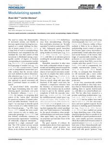
Fig. 1.1 Digital telephony standards [I] bandwidth speech heard over telephone network with bandwidth of 0-3400 Hz,
Com-
munication quality, with perceivable distortion but high intelligibility (MOS of 3.5), and
Synthetic quality, with unnatural yet highly intelligible characteristic. The
subclass of wideband speech is not the focus of this work. For the narrowband speech coding, Fig. 1.1 summarizes the current state of digital telephony standards showing the bit rate, quality and applications. t The CCITT coding standardization for low-delay high-quality speech coding at 16 kb/s is under way. Other current goals are the achievement of transparent or near-transparent quality at 8 kb/s and robust communication quality at 4.8 kb/s and lower.
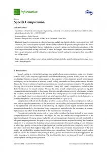
A summary of the CCITT standardization specification for the 16 kb/s low-delay coders is shown in Table 1.l. 3 Note the objective low-delay of 2 ms and the required channel error robustness. In future, similar kinds of requirements can be expected t CC1TT:Consultative Committee for Telephone and Telegraph, GSM: Group Special Mobile, $
CTIA: Cellular Technology Industry Association, NSA: National Security Agency. The qdu is a quantization distortion unit where distortion is due to a single stage of 64 kb/s PCM coding with an "average" codec. To calibrate codecs on the qdu scale the CCITT uses the MNRU, a reference unit known with a qdu characteristic. The MNRU is specified in a CCITT recommendation. P, is the channel probability of error. G.721 is CCITT standardization of 32 kb/s coders in 1984.
Parameter Coding Delay Pe = 0
I
CCITT Requirement < 5 ms Distortion < 4 qdu Not worse than G.721 Not worse than G.721 3 asynchronous tandems with distortion < 14 qdu
(
Objective < 2 ms
-
.
Pe = Pe = Tandeming for speech Transmit Signaling Tones Transmit Music Operate at lower rates
Synchronous Tandems
DTMF
Complexity
No annoying effects Graceful degradation As low as possible
Table 1.1 CCITT standardization - characteristics for low-delay 16 kb/s coders [l] for coding at bit rates below 16 kb/s. Depending on the area of the application (Network, Mobile Radio/Voice Mail), the requirements can be somewhat different than the ones in Table 1.1. For example for Mobile Radio or in-building wireless applications, channel error rates can be more severe than the rates in Table 1.1. Lowdelay coding at bit rates between S and 16 kb/s (medium bit rates) with transparent or near-transparent quality is the focus of this thesis. Possible additional requirement such as the ones in Table 1.1, are also considered. A Low-Delay Code Excited Linear Predictive coder (LD-CELP) coder is the AT&T candidate for the 16 kb/s CCITT standardization [2, 3, 4, 5, 6, 71. Iyengar and Kabal have suggested a Low-Delay Tree coder [8, 9, 101 (LD-TREE) based on the (M,L) algorithm and reported a performance quality equivalent to 7 bitslsample log-PCM at 16 kb/s. Under clear channel conditions (Pe = 0.0) both coders may be considered as potential candidate coders for the low-delay network-quality applications. Satisfactory performance quality, under channels with transmission error, is also reported for the LD-CELP. The performance of the two coders however has not been compared under the same conditions before. This is done when results of the
simulations of the two coders are compared in this work. The studies and simulations of this work and the ATScT's development of the LD-CELP coder were concurrent. t The original early version of the LD-CELP described in Ref. [2] was used for simulations in this work. However the detailed algorithm description and subsequent modifications reported later [3-71 were also considered. $ The evolution of many speech coding techniques contributes to the structure and components used by the LD-CELP and LD-TREE. Any improvements leading to better future speech coders will benefit from the lessons of this evolution. The structure of conventional Pulse Code Modulation (PCM) with p-law or A-law companding schemes is well known. First, the analog speech signal is passed through the band limiting filter (e.g. 3400 Hz). The sampler operates on the output of this filter to meet the Nyquist criteria (e.g. 8000 Hz sampling frequency). The p-law/A-law compression is introduced at this stage. At the final stage of the encoder, the amplitude quantizer assigns one of the uniform quantization levels (e.g. 256 levels) to the sampled and compressed signal (64 kb/s coder). The nonuniform quantization resulted from the combined compression and uniform quantization operations is more appropriate for the speech signal (log-PCM). The decoder performs the reverse operations (Inverse quantization, Expanding, and Interpolation filter). As seen in Fig. 1.1, in
1972 CCITT standardized these coders (G.711). Log-PCM coding scheme does not take advantage of the redundancies in the speech signal. Digerential Pulse Code Modulation (DPCM) and Adaptive DPCM (ADPCM) coding strategies, exploit some of these redundancies. Before quantization, a predictor filter is used to estimate the speech sample. The coder in effect quantizes the difference of the actual speech sample and the predicted sample. The structure of t Most of the work for this thesis was done during winter 1989 and bhe first half of 1990. The
writing however was interrupted and only concluded in early 1991. This is why the results of the thesis was reported prior to the conclusion of the final version of the thesis [ l l , 12, 131. Also the work is continued by J . Grass, the author and others at INRS-T616communications for the 12 kb/s based on the recommendations of this thesis [14]. Other suggestions for modifications, not reported at the time of this thesis were discussed in Ref. [15] (International Conference on Acoustics, Speech, and Signal Processing '91).
such coders is more formally introduced in the next chapter. The result is a gain in use of transmission rate of 2:l with coding rate at 32 kb/s with equivalent toll-quality of 64 kb/s log-PCM coders. As seen in Fig. 1.1, the CCITT standardization of the 32 kb/s coders took place in 1984 (G.721). The G.721 is also extended to 24 and 40 kb/s in G.723. This 2:l compression and the so called 2.5:l gains of Time Assignment Speech Interpolation (TASI) or Digital Speech Interpolation (DSI) (effect of silences in speech) results in an effective circuit gain of 5:l over conventional telephone systems. The wireless applications (short distance indoor) have benefited from the G.721 for its simplicity. The CCITT G.EMB standards is the extended (draft version) ADPCM application at rates 40, 32, 24, and 16 kb/s.
In the 32 kb/s standardization, no side information is transmitted and in order to minimize transmission delay, all adaptation processes are in a backward fashion [16]. The backward and forward adaptive prediction differ in the positioning of the buffer window of the samples in the prediction analysis. This means that for the backward adaptation, buffering of tens of milliseconds of the speech signal for prediction analysis does not include "future" samples (as it does in the forward adaptation), i.e. the predictor and quantizer are updated using information contained in the past reconstructed samples. This of course results in a small degradation in prediction quality. Lowering the ADPCM coder bit rate below 32 kb/s means lower bit rate available for the residual signal coding and higher quantization noise. The backward adaptive prediction which relies on the past reconstructed signal degrades rapidly as quantization noise increases. Hence, the coder toll-quality of the ADPCM algorithm can not be maintained at 16 kb/s. Although use of forward adaptation improves the performance at the cost of increased delay, as seen in Table 1.1, this encoding delay is specially undesirable for the network applications. The following paragraphs explain how other modifications are needed in order to simultaneously maintain coder quality and low-delay. The interface between the 4-wire to %wire lines with impedance mismatch generates echoes. The echo round trip delays result from a combination of encoding delay and (long distance)
propagation time. The application of echo cancellers at the 4-wire/2-wire junction reduces this echo. The amount of tolerable echo by the canceller is a main factor used to define the maximum and objective coding delays in Table 1.1. For the 16 kb/s CCITT low-delay standardization (currently under way, Table 1.1), the opposing goals of low encoding delay, speech quality have to be accornrnodated. The backward adaptive prediction has to be used if the delay requirement of Table 1.1is to be met. The computation cost of the many coding techniques combined in such a complex coder has to be kept limited to the computational power of the DSP chips available. As mentioned earlier, although channel error performance (and other) requirements are constrained by the limits of Table 1.1, for other applications such as mobile radio and indoor wireless, the channel error rate can be much more severe than the ones in Table 1.1. Both LD-CELP and LD-TREE coder belong to the class of Delayed Decision or
Multipath search coding which is introduced in detail in the next chapter. In the speech model where decision on choice of an excitation sequence deriving a reconstruction filter has to be made, number of samples in the sequence defines the encoding delay. The actual coder delay is 2 to 3 times this encoding delay mostly due to buffering and processing time considerations. In order to obtain 16 kb/s bit rate with a sampling frequency of SO00 samples per second, the coder can only use 2 bitslsample. The choice of tree or codebook for the excitation sequence is the main difference between the LD-CELP and LD-TREE. The simulations results of this work (presented later) show that the two coders have comparable performance at 16 kb/s under clear channel conditions. Other contributions of this thesis include methods to improve the performance of the two coders, particularly with the view of bringing the bit rate below 16 kb/s (medium rates 816 kb/s). The (original) two coders used different methods and strategies for their components. The analysis and improvements to these components (formant-pitch prediction schemes, gain scaling methods of the excitation sequence, types of the perceptual weighting for the error signal, etc.) are also important for the purpose of better coders at 16 kb/s and below. The challenge is to develop high-performance
compatible components for the target future coder, operating at bit rates between 8 to 16 kb/s. In particular, the backward adaptive prediction component is investigated at length in this thesis. Suggestions to improve the two coders include an improved high-order predictor (applicable to both coders), training of the excitation dictionary as well as a better gain adaptation strategy for the tree coder. The high-order prediction alternative is compared to the conventional formant-pitch configurations. The performance of high-order predictors is studied and greatly improved. Concluding from the advantages of each of the two coders (LD-TREE and LDCELP) and the choices of the individual components, suggestions are made to combine CELP and tree structures for future coders. A hybrid coder, taking the best components from the two archetypes (possibly with a "Tree-CELP" structure) is a good candidate to push coding rates below the current 16 kb/s. Future high-quality lowdelay speech coding at medium rates should benefit from such combined structures and schemes. t
1.1
Organization of the Thesis In Chapter 2 the overall structure, components, and concepts of low-delay speech
coders in general and the two coders (LD-CELP and LD-TREE) in particular are discussed. Chapter 3 focuses on the backward linear prediction. Issues and methods of pitch and formant prediction are investigated. The experiment results on the backward linear prediction methods of Chapter 3 are presented in Chapter 4. Chapter
5 gives a detailed description of the two coders algorithms. It also discusses ways of improving both coders. The discussion on the nature of the differences and similarities between the two coders leads to the recommendations for future hybrid coders which combine the best of both coders. Summary and recommendations for future work are in the final chapter.
t The work of low-delay speech coding at 12 kb/s in Ref. [14] utilizes the above recommendations.
- 7-
Chapter 2
Low-Delay Speech Coding
This chapter presents a review of the various components of high-quality low-delay speech coders at 16 kb/s and below (medium rates 4.8 to 16 kb/s). The thesis focuses on LD-CELP and LD-TREE coders. The discussion provides both background and insight into the components of these two coders. The general techniques ~f analysisby-synthesis and Delayed-Decision coding are first introduced. Then, the overall. structure of the LD-CELP and LD-TREE coders are presented. Various components of the two coders as well as similarities and differences between them are studied.
2.1
Introduction
Prior to toll-quality low-delay speech coding at medium rates, many barriers of achieving better coders with lower bit rates were broken. The bandlimiting filter which is used before sampling of the analog telephony signals', limits the signal frequency higher band to 3400 Hz. A sampling frequency of 8000 Hz in the conventional method of Pulse Code Modulation (PCM), along with the p-law or A-law companding methods and a uniform quantization of 256 levels (8 bits/sample) result in 64 kb/s coding rate. The above method of log-PCM which has the obvious advantage of zero delay, does not take advantage of the of the correlations among the samples. The method of Differential Pulse Code Modulation (DPCM) exploits these redundancies to bring down the coding rate. This method includes a linear predictor filter which produces a predicted sample value corresponding to each speech sample. The quantizer quantizes the prediction error signal which is the difference between the current
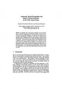
sample value and the predicted value. If the selection of the predictor coefficients as well as the quantization are chosen to be adaptive to the stationary characteristics of the signal and the dynamic range of the predicted error signal respectively, the coding rate is further reduced (Adaptive Differential Pulse Code Modulation or ADPCM). The conventional ADPCM structure is shown in Fig. 2.1. The two components of the conventional ADPCM are the quantizer Q and the predictor F ( z ) . It is well known that the quantizer Q and the predictor F ( z ) (the z-transform of the prediction filter response f (n)) have to be in a closed-loop configuration (such as the one in Fig. 2.1) so as to minimize the effect of the quantizer error in the coded speech [17, 181. The CCITT's standardization for the speech coders at 32 kb/s uses ADPCM to produce toll-qualit y speech.
u (a) Encoder
u
(b) Decoder
Fig. 2.1
Conventional ADPCM coder
The strategies of the method of ADPCM can not yield 16 kb/s bit rate coders which can maintain both toll-quality speech and low delay. As it was mentioned in Chapter 1, the high quantization noise and the resulted poor backward prediction degrades the coding quality. The alternative of forward adaptation is not considered since it introduces coding delay longer than network application toleration. In the forward adaptation, in order to estimate the parameters of an adaptive operation, often an analysis frame of tens of milliseconds is used. As an example an analysis frame of 160 samples (20 ms for the SO00 Hz sampling frequency) may be used. The
encoder estimates these parameters based on some optimization procedure and then uses the obtained parameters for those 160 samples. The parameters are transmitted as side information to the decoder. Since it is necessary to have an analysis buffer of 160 samples, a delay of 160 samples or 20 ms (for the sampling frequency of 8000 Hz) is resulted. Backward adaptation means that blocks of reconstructed signal, up to the present sample, are used for the analysis. Since these quantized samples are available both to the encoder and decoder, there is no need for transmission of side information. The real advantage is the elimination of the analysis buffer of future samples which means no delay. The cost is a small performance degradation due to two facts: first, the quantization error has a negative effect on the future sample quantization which is based on the reconstructed samples, and second the analysis window in the backward adaptive case only includes past samples and hence the analysis does not benefit from the future samples (the parameters may be "stale"). The generalized A D P C M coders may use time-varying linear predictor filters to model far-sample as well as near-sample correlations. The near-sample filter models the spectral envelop with resonances (called formant) and antiresonances. The resonances are due to the poles of the vocal tract frequency response, while some spectral nulls are due to zeros of the response. The spectral fine structure (pitch) is modeled by the far-sample prediction filter. These models discussed in Chapter 3 remove the speech signal formant and pitch redundancies and hence reduce the required bit rate. The "noise shaping" consideration of the generalized Adaptive Predictive Coding (APC) structure is an improvement over the ADPCM one. In the ADPCM model the output error signal is approximately white. This does not explore the human perception characteristics. The distortion in the coded speech is less likely to be perceived by the human ear at frequencies where the speech signal energy is high. The desired noise shaping scheme, filters the quantization noise so that it has the same spectral shape as the input speech (increased noise energy in formant regions but decreased elsewhere). As a result, there is a bias toward less noise at low frequencies. This is because the speech spectrum masks the perceived noise to some degree and the fact that the ear is more tolerant to the noise at high frequency. The noise shaping filter
system function is often chosen to be a bandwidth expanded version of the transfer function of the formant predictor. The generalized APC structure allows for this kind of control over noise spectrum. This structure which has a closed-loop configuration is shown in Fig. 2.2.
(a) Encoder
(b) Decoder Fig. 2.2
A closed-loop configuration coder
Other than the two components Q and F ( z ) (quantizer and formant predictor) which were previously seen in the conventional ADPCM of Fig. 2.1, the generalized closed-loop structure includes a pitch predictor P ( z ) and a noise shaping filter N(z). In this configuration the feedback loop is around the quantizer and the closed-loop includes the pitch predictor. The additional noise-shaping filter reduces the perceived distortion. The configuration of Fig. 2.3 is suggested for the general open-loop configuration [19]. In this structure the formant redundancy removal precedes the pitch
redundancy removal (F-P open-loop configuration). The open-loop configuration of Fig. 2.3 also includes a noise feedback filter (but not explicit). This configuration which is used in the CELP coders, may also be used as an alternative to the closedloop configuration in the APC coders. The discussion of the next section introduces
u (a) Encoder
(b) Decoder
Fig. 2.3 An open-loop configuration APC coder with noise feedback Linear Predictive Coding (J..PC). A full discussion of the formant and pitch predictor used in configurations of figures 2.2 and 2.3 are postponed to the next chapter. Analysis-by-synthesis scheme which provides a better control over quantization noise is another concept used in the LD-CELP and LD-TREE -coders. Next section reviews the LPC model of speech in an analysis-by-synthesis configuration. The class of coders which make the task of high-quality low-delay speech coding possible, is the Delayed-Decision Coding or Multipath Search Coding. Codebook, Tree (employed in the LD-CELP and LD-TREE coders respectively) and trellis coding structures all belong to this class of coders. They employ encoding delay (here within the allowed low-delay requirements) to identify the best possible sequence out of a set of alternatives. 0ther low-delay components such as Gain adaptation, Postfiltering are also reviewed in this chapter.
2.2
LPC model and Analysis-by-Synthesis The redundancies in natural speech are a direct result of human vocal tract struc-
ture and the limitations of the generation of speech as well as human hearing and perception. Various coding methods exploit these redundancies taking into consideration the following facts:
In general, vocal tract shape and thus speech spectrum change relatively slowly compared to the sampling frequency (although abrupt changes occur at closures of vocal tract); The vocal cords vibrate rapidly but the change in the vibration rate (i.e. FO, the fundamental frequency) is relatively slow; Successive pitch periods are very similar most of the time; The vocal tract spectrum varies slowly with frequency, and most speech energy is at low frequency; Speech.sounds can be modeled as periodic or noisy excitation passing through a vocal tract filter, and each sound can be represented with a' few parameters; Characteristics and limitations of human audition such as higher sensitivity to lower frequency, insignificance of spectral zeros, phase insensitivity, and masking phenomena can be used [17, 181. The linear predictive coding (LPC) is an important speech model which uses the above facts and is used in many speech coders including the generalized ADPCM and APC. The basis for the LPC model is the production of speech via a linear filter system representing the human speech synthesis. An excitation source U(z) (representing the z-transform of time sequence u(n)) is the input to a shaping filter H(z) to produce S(z) the output speech. As a possible excitation signal, U(z) may be chosen from a carefully picked excitation dictionary. The time domain equivalent representation shows how a linear combination of the p previous output samples and q
+ 1 previous input samples are used to predict
i ( n ) (with a gain factor G):
In most cases, the all-pole Auto-Regressive model (AR, q = 0) is chosen over the all-zero Moving Average (MA, p = 0) or the general pole/zero ARMA model (Eqn. 2.1). A drawback of this choice is that the spectral zeros due to the glottal source and/or vocal tract response in nasal and unvoiced sounds are not represented. However an additional 2-3 poles can approximate the zeros closely. When the all-pole model is used, using the z-transform of Eqn. (2.1), H(z) may be written as: Hb)=~
G
( r )where
A(z) = 1 - F ( z ) = 1 -
P akr-k. k=l
A(%) is called the inverse filter (the inverse of the all-pole H(r)). If the input t o the inverse filter A(r) is speech signal S ( z ) , the output is E ( t ) which is called the prediction error signal. As shown in the general configurations of the previous section, various coding methods use the LPC model in removing both far-sample and near-sample redundancies. The variations of these structures and adaptation schemes are discussed in detail in the next chapter. The generalized ADPCM and APC use such structures to produce high quality speech at rates between 16 to 32 kb/s. As mentioned earlier, the APC has the advantage of control over the noise spectrum and hence produces better results. When medium rate coders (4.5-16 kb/s) are needed, an even better control over the distortion resulted from the quantization is needed and one needs to increase the efficiency of the residual signal quantization. The method of analysis-bysynthesis improves the control over distortion by minimizing the error at the encoder between the reconstructed (output) signal and the original signal [20]. Fig. 2.4 shows an example of analysis-by-synthesis configuration which is used in the CELP and other coders [21, 22, 23). This configurations is explained in the next paragraphs.
1
1-P(z)
+ Fig. 2.4
-
1
A-*-
l-F(z)
Min. MSE
....s I
An analysis-by-synthesis configuration
The reconstructed signal is the output of the speech production model. In order to perform the error minimization procedure, encoder must include a replica of the decoder so that the identical reconstructed signal becomes available at the encoder. As seen in the Fig. 2.4, easy incorporation of the perceptual weighting filter (W(z) =
a))
is an advantage of the analysis- by-synthesis structure. The synthesis filters
1
i q q and i q q are all-pole filters
similar to the one in Eqn. 2.2 which are used
for near-sample and far-sample redundancies. As it is seen in the next chapter, a
single (high order) synthesis filter may replace the two separate formant and pitch filters (pitch synthesis filter is eliminated in Fig. 2.4.). The discussion about the adaptation of parameters in F ( z ) and P ( z ) is also postponed until the next chapter. The excitation signal is not necessarily one single sample as it is the case in the simple analysis-by-synthesis structure of Fig. 2.4. As seen in the next section it is possible to have a sequence of samples as the excitation sequence. The excitation sequence (or sample) is determined such that the Mean-Square perceptually weighted Error (MSE) between the original and the reconstructed signal is minimized. Adaptive gain scaling of the excitation signal (gain component after the excitation signal in Fig. 2.4) improves the excitation representation by reducing the dynamic range of the excitation set. The excitation signal is multiplied by the gain factor and then passed through the synthesis filter(s) to generate the reconstructed signal. This section of the structure is common to the encoder and the decoder. The error signal is passed through a perceptual weighting filter prior to the error minimization. Methods to decrease the computational complexity of the analysis-by-synthesis configuration are discussed in Section 2.7. Computational reductions are obtained by better placement of the perceptual weighting filter and by the separation of Zero-Input Response (ZIR) and Zero-State Response (ZSR) of the system.
2.3
Delayed-Decision Coding
The methods of Delayed-Decision Coding, which result in the CELP, Tree, and Trellis coding, are excitation sequence procedures which are discussed in the this section. Other excitation methods such as Residual-Excited Linear Prediction, Multipulse and Regular-pulse excitation coders which also belong to the class of analysisby-synthesis are found in the literature [24, 25, 171. Through the use of Delayed-Decision Coding, an efficient representation of the residual signal is possible. A delayed decision is made as to which optimum residual quantization value has to be selected. A sequence of future values of speech signals as well as the current sample are used. This allows the realization of rates R
10 would not be
appropriate ( D = 10 is chosen in this work). More detail discussion and the results related to the above issues are discussed in Chapter 5.
2 -4
Perceptual Weighting Filter
Two forms of perceptual weighting (noise shaping) filter are considered. The simpler and more conventional form is W(z) =
1- F(z) 1 - F(z/X) '
P
where
F(z/X) =
C oiXizi i= 1
is the bandwidth expanded version of F ( z ) (e.g. X=0.85). The more general weighting filter has the following form
where
with 0
< X2 < X1
0 for n > 0 [50]. If y = 0.5 is used, the reflection coeffi-
cient update expressed in terms of expect ation quantities (instead of windowing) of Eqn. 3.12 will have the form:
I{m+l(n
+ 1) = Fm(n) 2Cm(n) + Bm (n)
'
The adaptation of parameters in the above Burg-Lattice method is performed on a sample-by-sample basis. The methods of Covariance-Lattice [51, 521 use the recursion formulations of the regular Lattice (Burg) method to obtain a more computationally efficient procedure. Using the recursion formulae of 3.10, quantities of 3.12, and the Burg update formulation of 3.16, one may arrive at: m
m
i), r F m ( n ) = C C a k(m)a(m)$(k, k=O i=O m
Bm(n-1) =
C
m
(m)a!m)$(m
b=O i=O m m
+ 1 - k, m + 1 - i), +
a~m)cz~m)$(k, rn 1 - i),
C,(n) = k=O i = O
$(k, i ) =E{s(n - k ) s ( n - i ) ) , where $(k, i) is the covariance (non-stationary auto-correlation) of the signal. Consequently, the reflection coefficients of the Lattice met hod (Equations 3.12 and 3.16) are updated using the estimated covariance (hence the name Covariance-Lattice). Using this method the computation cost will change from 5 P N (Burg method) to PN
+ l / 6 p 3 + 3/2p2 ( N being the analysis window length and P the predictor
order). -
Another important modification to the above calculation is the one suggested by
Cumani [52]. In an attempt to fit the method better to fixed-point arithmetic, in effect all quantities are scaled for better numerical stability. The price is a slight increase in computational complexity. The detail description of Cumani method is
now described. First the following quantities are defined.
-.
m
-
Bm(i,j)=
C
m
+
C a ~ m m ) a ) m ' + ( r n1 + i - k , m + 1 k=O Z=O m
m
C
+
aLm)arm)+(i k, rn k=O 1=0 $(k, i) =E{s(n - k)s(n - i)),
Cm(i,j ) =
+ j - 1), (3.18)
+ 1 + j - 1),
with special cases of J'm(0,O) =Fm(n),
Cm (0 0) = e m (n)Using the calculated covariance matrix (Eqn. 3.6) with entries {$(k, i)) , we initialize the algorithm with m = 0,
Co(i7.j) =4(i, j
+ I).
TOobtain Fm(n), Bm(n - l ) , and Cm(n), using the relationship between the reflection and prediction coefficients in Eqn. 3.9 and the above quantities the following
Results in Chapter 4 indicate that the Cumani method has excellent numerical properties in the context of backward adaptive high-order prediction (Use of Cumani algorithm for the high-order predictors is new.). Strobach [53] discusses this method further and generalizes it to the methods of Generalized Residual Energy (GRE) with the same numerical properties. In this general class (which also includes solution of the true Recursive Least-Squares (RLS) Covariance-Lattice estimation problem), coefficients are constructed completely anew at each step, avoiding round-off error accumulation. As later seen in Section 3.6.5, the computational complexity disadvantage
of Cumani algorithm ( 0 ( p 3 ) ) can be overcome using Strobach Covariance-Lattice methods (0(p2)). The class of such algorithms is also termed Pure Order Recursive Ladder Algorithms (PORLA).
N,ear and Far-Sample Redundancy Removal
3.5
The methods of removal of both near and far-sample redundancies (prediction) from the speech signal using prediction analysis methods maybe summarized as follows:
1- Combinational formant /pitch Single Predictor (possibly high-order): l ( a ) With equally spaced predictor taps l(b) With selectively spaced predictor taps 2- Separate pitch and formant Predictors: 2(a) Sequential 2(b) Jointly Optimized Sequential 2(c) Decoupled Sequential of Ref. [44] -
-
-
-
- -
The range of pitch which has to be considered
for the natural speech is from 64 Hz
to 400 Hz. Using the sampling frequency of SO00 Hz, the required upper correlation lag to be considered is 125 samples (120 samples is commonly used). Typical male speech uses a Fo (fundamental freqilency) range of SO to 160 Hz [17]. With average male and female Fo at 132 and 223 Hz, the corresponding distance between pitch spikes in the time domain signal are 61 and 36 samples. Hence for the average pitch lag considerations, correlations corresponding up to 61 lags are needed. The first method l ( a ) , attempts to remove the far-sample redundancies using the same predictor used to remove the near-sample redundancies by having the order of the prediction error filter A(z) = 1 - F ( z ) very high. Ideally the order of the predictor has to be high enough to include past samples corresponding to the lowest pitch (around 120 samples). As mentioned earlier, this approach has the following two problems. First is that the computational cost of such prediction analysis would be enormous and as shown from the experiments of the next chapter, there are numerical problems which
- 47-
arise at such high orders. As a compromise solution to this problem, a prediction order of manageable computational complexity has to be chosen (e.g. 50). Order 50 allows "capturing" of the female speaker pitch and some portion of the male speaker pitch range. Hence the full range of pitch for all speakers (especially for male) which "extends" to delays as far back as 120 samples is not covered. The second problem with the very high predictor orders is related to the correlation estimations and the analysis window selection. All prediction methods are based on some kind of correlation estimation for which the length of the analysis window must be large enough to provide a valid estimate of the far-sample correlations (2-3 times the longest lag 120, which gives a window lag of up to 400 samples long). If the formant structure is stationary during analysis periods of this size (400 samples), this problem would not cause any loss in prediction gain. However since formant structure is not stationarity during periods longer than 100 samples, the use of long analysis windows results in poorer tracking of the changes in the formant structure. The commonly used analysis window size of around 20 ms for prediction order 10 proved to be a good compromise for most cases for high-order prediction (see the results of the experiments in the next chapter). However this compromise along with the numerical problems are the reasons why the prediction gains for male speaker only increases slightly at prediction orders around 60 to 70. One would have expected a higher rise (as is for the female speaker) in the prediction gain around these orders for male speakers. One reason that Ref. [2] probably chose order 50 is because they did not get significant prediction gains beyond order 50 while in fact it should be possible especially for male speakers. The second method 2 ( b ) , may be used with different variations in selecting the spacing of the prediction taps. The goal is to place the taps where correlations are high and the effect of redundancy removal is high both in terms of prediction gain measure and the subjective quality measure. Experiments were carried out to investigate the allocation of taps. R.esults of some of these experiments are mentioned in the next chapter. One attempt allocated 20 taps (delays 1-20) for formant tracking and 30 taps for the far-sample correlation tracking. The difficulty in this case is how to
choose the location and spacing of the far-sample taps. One way is to select them with fixed positions. The goal would be to use the avaliable taps to either cover the whole range of delays from 20 to 120 lags or use them so as they are located at more probable pitch lags (e.g. 30 for female and 60 lags for male). Another way to allocate the taps would be to set them around the current pitch lag in such a way that the tracking of the pitch is adaptive. The windowing problem discussed earlier is one difficulty encountered for this approach. A consequence of the arbitrary tap-spacing method is that the auto-correlation matrix would not be Toeplitz. Another problem which occurs more strongly in the case of arbitrary tap-spacing methods is higher ill-condi t ioning . The alternative configuration of two separate predictor (methods of 2(a), 2(b), and 2(c)) for pitch and formant as in Fig. 2.3 and 2.2, does not have the windowing problem of the method of a single predictor. Selecting two different sizes of analysis window used for the two predictors is now possible. Better overall prediction gain at the cost of higher computational cost is obtained when the pitch and formant coefficients are joint optimized [19] (2(b)). As discussed earlier, due to the coupling between the two sequential predictors, the performance of such schemes is poor under channel errors. Some success is reported, when in a special configuration, the two predictors are decoupled [44] (method of 2(c)). In the suggested configuration, a pole/zero model is used for the formant predictor. The adaptation of the polecoefficients of the formant predictor (decoder of Fig. 2.3) is done not based on the synthesised speech but rather on the signal which does not have the pitch content reasserted (only formant zeros of the speech are reasserted)(see Ref. [44] for details).
3.5.1
Pitch Adaptation in Sequential Configuration
The adaptation of pitch parameters for the sequential pitchlformant configuration, described in detail in Ref. [46], is now briefly reviewed. Assuming that the pitch predictor's order is Np, and the estimated pitch lag is PIp, the z-transform of the
predictor may be written as: NP
P(z)= C b i z - M p - i - 1
(3.22)
i= 1
The covariance formulation for the linear predictor using an analysis window size of
N samples, results in the following set of equations:
where
N-1
d(n - i)d(n - j) .
$(i, j) =
(3.24)
12=0
and d(n) is the input signal to the pitch predictor (Fig. 2.3). The short form notation for the above set of equations is @c = q. The estimation of the pitch lag Mp is obtained by the minimization of the mean-squared error which has the form: c2 = d(0,O) - c T 9 . Consequently c T 9 is maximized as $(O,O) is constant. Using the assumption that the near-sample correlations are removed from the input d(n), the simple approximation of
cT q z
2
h/l,+Np-l
4 (o,m>
m= Mp
$(my 4
(3.25)
results, where the off-diagonal terms in the matrix @ are neglected.
3.6
Other Issues in the Backward Linear Prediction
In carrying out the experiments of the next chapter, the following issues were found of importance: 123456-
Synthesis filter stability and the minimum phase property, Optimality, Window shape and size, Computational issues related to the ill-conditioning, Complexity (including parameter update rate), Backward adaptation and quantization noise effects.
This section discusses the above issues in the various analysis methods. The experiments of the next chapter complement this discussion and some of the comparisons made here. The discussion and the experiments also show how factors like numerical stability and optimality effect each other. The choice of method of practice will also dependents on the real time implementation circumstances.
3.6.1
Synthesis Filter Stability/Minimum Phase Property
Lattice and Lattice-Covariance methods have the advantage that stability (minimum phase) of the resulting synthesis filter can be guaranteed. This is by ensuring that all reflection coefficients are all less than one. This is equivalent to guaranteeing that all zeros of the prediction error filter 1 - F ( z ) be inside the unit circle. Also in these meth3ds it is possible to have a control over weighting of the forward and backward error in minimization of the mean squared error (although stability is only guaranteed under the weighting factor of 0.5 for forward and backward error). The Auto-Correlation method and the Covariance methods lead to stable (minimum phase) prediction error filters while the general form of arbitrary tap-spacing methods does not guarantee this 1191. The equally spaced tap delay of the form Mk = kM1 is a special case for which the minimum phase property is true.
3.6.2
Optimality
In a general sense, various linear prediction methods use different optimality criteria. In a mean-squared forward error minimization sense however, the AutoCorrelation and Covariance methods are the only methods which give optimality. The methods of Lattice and Lattice-Covariance are only possibly sub-optimal [51]. One may argue that in the backward adaptation, the LLoptimality" is with regard to the analysis frame (and not with respect to the sample(s) for which analysis is actually used). Ref. [lo] suggests that the simple white noise correction actually results in a better prediction gain by "de-tuning" the adaptation which is too "tuned" to the analysis frame (past samples).
3.6.3
Window Shape and Size Considerations
The shape and size of the two windows of Fig. 3.1 are important elements which effect theperformance of the predictor. The selection of window also has cross-effects on other analysis components listed previously (e.g. the ill-conditioning and complexity). In the backward adaptation analysis, exponential windows which emphasis the more recent samples seem to perform better than commonly used Hamming and Rectangular windows. The length of the window (or the effective length of causal semi-infinite windows such as exponential windows) is chosen so that the correlation estimations contains enough number of samples to make the estimation valid. Once again the general rule of 20 ms window length maybe used where compromise has to be made between accuracy of estimation for long delay correlations and minimum averaging for short correlations. Computational complexity as well as stability of the resulted synthesis filter are also important when selecting the window w(n). If the window is chosen so that w(n) 3 0 for all n 2 0, the sufficient condition for the stability of the synthesis filter is satisfied.
A class of windows obtained using the impulse response of casual pole/zero filters provide easy control over the shape of the window. At the same time their recursive implement ation is advantageous (complexity and implementation considerations). These windows may also be regarded as exponential windows since the impulse response may be generated as the sum of exponential terms. The z-transform of the general filter of this type has the form:
Examples of windows considered in the experiments of the next chapter are the simple
one-pole exponential and other windows with a small number of zero and poles: 1 pole : - --
--2 pole :
2 pole
+ 1 zero :
w2pz(n) =
-u(,O~)~,
where ,f3 is a number close to one (0 < ,O 5 1). The choice of the window shape and length (effective length in the case of exponential windows) is important. The effective length of the general window w(n) is defined as [50]:
When this definition is applied to the pole/zero exponential windows of Eqn. 3.27, the effective length of these windows (in samples) are found: 1 pole:
L1 =-1 + P 1-p7
2 pole :
(1 P)3 L2 = ( I - ,q(1 P2)'
3 pole : L~ =
2 pole
+ 1 zero :
LSpz =
+
(1 (1 - P)(l
Im
1
+
+ P)5
+ 4P2 + P4) ' -
Q
2
1 2a . mf+&F--
The effect of the shape of the window maybe expressed as a function of what is termed as "measure of capture" in Ref. [50]. Although helpful, this factor does not give the full effect of the window shape in the predictor performance. This measure quantifies the amount :f weight which window puts on the immediate past speech or the amount of signal "captured" under the dominant portion of the window and is defined by:
L is the effective length of the window and C is the fraction of area under this effective length. For the 1 and 3-pole windows, C1 and C3 are 0.9865 and 0.904 and C for the Rectangular window is 1. Slightly better results are obtained with higher order windows (2 or 3 pole over 1 pole window) at the expense of increased complexity. Fig. 3.3 shows the time response of the windows obtained using a 1 pole and a 2 pole
+ 1 zero model.
Two windows
obtained using 2 pole model with different effective lengths are shown in Fig. 3.4. To emphasis the effect of the far-sample correlations, the effective length of the window used with the 50th order predictor should be slightly longer than the one used for the order predictor (20 ms versus 14 ms in this case). 0.3
I
I
n
e
w
3
...................... 0
100
200
Fig. 3.3 1 pole window with ,B = 0.986 (dashed line) and 2 pole + 1 zero window with P1 = 0.97, ,B2 = 0.95, and a = 0.85 (solid line) (Effective length of the dashed window is 142 samples and of solid line is 97 samples. Two windows are normalized to the same area.)
The above windows may be applied to the data or error signal as was shown in Fig. 3.1. The exponential data-windowing of 1, 2, or 3-pole (Eqn. 3.27) was studied by Barnwell [54] in order to provide a recursive windowing method in generating auto-
Fig. 3.4 2 pole window with P = 0,965 (dashed line) and 2 pole window with ,B = 0.975 (solid line) (Effective length of dashed window is 112 samples and of solid line is 158 samples.)
correlation lags in prediction analysis. For the real-time implementation, especially if high-order prediction analysis is used, the recursive feature is beneficial. Windows of Fig. 3.4 are examples of the Barnwell windows. As experiments of next chapter and Ref. [3] show, the Barnwell Auto-Correlation method used in the backward adaptive prediction analysis gives better subjective and objective prediction gains over the Hamming window. This is due to the fact that the exponential windows emphasis the immediate past samples more heavily. To ralculate the auto-correlation terms, the speech signal is passed through specially-structured filter banks [54]. For the one pole window (Eqn. 3.27), each filter in the filter bank is a first order filter which is used to obtain one correlation term. For the two pole window, each filter is a third - 55 -
order filter. The transfer function of such filters are as follows. 1 pole (or 1 pole data window )
3 pole11 zero lag window
&(z)
pml2
Wm(r) = =
1 - pz-l'
+ +
prnI2[(1 m) (1 - m)pz-'1 (1 - pz-93
(3.29) 7
(or 2 pole data window) which is the z-transform of weighting window w m ( n ) applied to the lag-products (s(n)s(n- m ) )with the subscript m referring to the lag number. For the two pole window, a preferred implementation of the above 3 pole11 zero lag window is by cascading two 1-pole windows and one 1-polell-zero filter. The transfer function of these two filters are as follows
This implementation has computational advantages for the real- time implementation
171 The exponential windows are also applied to the error signal both in the Covariance method [55] and the Lattice method [50, 91. The results of the next chapter (and of Ref. [9]) show a better performance when the exponential error window is used in the Lattice method and when Hamming window is used in the Covariance method [55]. Once again, this is due to heavier weighing of the immediate past error
3.6.4
Computational Issues Related to the Ill-Conditioning
Due to gradual roll-off in the frequency response of the low-pass filter used before the Analog-to-Digital-Convertor ( ADC) used on the speech signals, artificially low eigenvalues for the covariance matrix
are produced (*a = \E). These eigen-
values are related to the missing high frequency components in the sampled speech signal near half the sampling frequency. This condition creates an almost singular covariance matrix (with large eigenvalue spread) which results in non-unique solution for the prediction coefficients. The small eigenvalues produce artificially large valued
prediction coefficients which if used, results in noise enhancement [48]. Here for this matrix "ill-conditioning" the term "Physical ill-conditioning" is used [56]. Error accumulation resulting from the use of fixed-point arithmetic is another reason for ill-conditioning. An almost singular matrix can easily become singular if error is accumulated due to computer smaller memory word length. The term "numerical ill-conditioningv maybe used for this kind of condition. The high frequency correction procedure described in Ref. [47, 481 decreases the physical ill-conditioning. It uses a new covariance matrix which is obtained by adding another matrix proportional to the covariarice matrix of the high-pass filtered white noise to the original covariance matrix. The solution considered, artificially introduces the missing high-frequency components. The (i, j)-th entry of a new covariance matrix a new correlation vector
&, and
the i-th entry of
G , are defined by:
where A is a small constant (10-~-10-~),emin is the minimum value of the meansquared prediction error, and p(i) is t he auto-correlation of t he high-passed filtered white noise at delay i. The resulted new system of equation is then solved. The suggested high-pass filter (cancelling the effect of the band-limiting low-pass filter before ADC) has the following z- transform:
for which the white-noise auto-correlation terms are
I:
p(i)=
I
1 4 1 -
16 0
for i = 0, for i = 1, for i = 2, for i 2 3.
The value of rmin is obtained by the Cholesky decomposition of the original matrix
a. If
the solution to the matrix is obtained through Cholesky decomposition, this
method requires a much higher complexity (the decomposition has to be used twice, once to obtain c,in from O and once to solve
8 ) .To avoid high computation
cost
of the above method, one may reduce the above white noise correlation technique to is a small constant a scheme in which kmin
to
and the only non-zero
p(i) is p ( 0 ) = 1 (or possibly p(0) and p(1)). The effect of the white noise correction technique is a reduction in the dynamic range of the signal spectrum hence reducing ill-conditioning . Numerical ill-conditioning is related to the particular algorithm and the computational procedure used. Error accumulation can be more severe for some methods. For example formulation of the algorithm in Cumani Covariance-Lattice method reduces the numerical ill-conditioning by resolving the problem anew at each step. The results of the next chapter for the high-order predictors show that the simplified technique (adding a percentage to the diagonal elements) sufficiently takes care of the inherent physical and numerical ill-conditioning. As seen in the results of the next chapter, the accumulation of numerical errors seem to have more severe effect in recursive methods for obvious reason. Also the Covariance method showed more severe problem than the Auto-Correlation method. In the experiments, to "cure" the "physical" and "numerical" ill-conditioning, the simplified white noise correction method (adding a percentage to the diagonal elements) gave better results than the full white noise correction method (it is also less complex.).
3.6.5
Computation Complexity
Table 3.1 compares the computational complexities of the various met hods. Examples for prediction order (P) and the resulting cost shows how the cost consideration may effect the choice of the computationally economical method for different orders. N is the analysis window size and M is the analysis and coefficient update rate (in samples). Note that the Cumani method with the best prediction gain performance has a very high computational cost. However, the computational disadvantage
Computation order *
Method Auto-Correlation
(PN+P~)/M
Covariance
(pfV+P3/6+3p2/2)/~
Lattice (Burg)
5PN
Cov.-Lat. (Makhoul)
(PN+P~/~+zP~)/M
Cov.-Lat . (Cumani)
(PN+4P3/3- P ~ ) / M
GRE (Strobach)
(PN+~P~)/M
* Zeroth order terms have been neglected. Table 3.1
Comparison of the computation costs ( N = 160)
of the Cumani algorithm ( 0 ( p 3 ) ) can be overcome using the Strobach CovarianceLattice methods ( 0 ( p 2 ) ) . In the backward adaptive prediction analysis, the parameter update may be done on a sample-by-sample basis or maybe done less frequently. When the update is not on a sample-by-sample basis (M > l), estimated prediction coefficients based on an analysis frame of past samples are used for the current samples and a few future samples. At the cost of small degradation in prediction gain, less frequent update rate reduces the computationa,l complexity. In obtaining a good prediction gain with an economical computational cost, one may choose to use a computationally expensive scheme but with an update rate which is not on a sample-by-sample basis. Some of the analysis schemes mentioned in the earlier sections may not allow update rate less frequent than the sample-by-sample update ( M
> 1). Auto-Correlation,
Covariance, and Covariance-Lattice methods have the advantage that analysis of the blocks are independent and may be done at any frequency (less often than sampleby-sample). This computational advantage is maintained even when a semi-infinite window is used, since most of the computational cost is for the solution of the linear system. For the Lattice analysis, an update with frequency less than sample-bysample is not possible. As seen in the experiments presented in the next chapter, the degradation in prediction gain as a result of less frequent update than sample-bysample, is minimal in comparison with the computational saving resulted.
3.6.6
Backward Adaptation Effect and Quantization Noise
The backward adaptation does not require transmission of any side information (prediction coefficients) and eliminates any analysis delay due to the buffering of the data for the analysis. The method however has two important drawbacks. First, the prediction gain is slightly reduced due to the fact that the prediction analysis is based on the quantized signal rather that clean signal. Second, the use of past speech for the estimation of prediction coefficients of a present sample makes the coefficients less fit for that sample ("stale" coefficients). This effect is even more pronounced when the update rate is less frequent. Effects of the quantization noise in the backward adaptation may be modeled and studied by the incorporation of a simulated quantization noise model. For the purpose of this model, the following assumptions are made. (1) The quantization noise is white, (2) The quantizer noise energy depends on the energy of the prediction residual. (3) The quantizer Signal to Noise Ratio (SNR) (the ratio of the prediction residual energy oa to quantization error energy
0%)is
fixed for an analysis frame. If
SNRQ represents the fixed signal to noise ratio of the quantization (e.g. 10 dB), one may derive the following relationship for the noise variance
where PG is the prediction gain and
05:
05 is the input speech signal variance.
The
quantization noise energy is added to the diagonal elements of the Covariance matrix or the auto-correlation matrix. The level of noise is iteratively adjusted for each analysis interval until the specified SNRQ is achieved. The algorithm outline is as follows. For each analysis block
1- Start with a high level of quantization noise (a fraction of the input signal energy, e.g. ON = O.SaS), 2- Calculate 9 or R matrix based on clean speech,
3-
Add 0% to the diagonal elements and perform prediction and calculate the residual variance, 4- If SNRQ has converged sufficiently to the fixed value (e.g. l o ) , stop, if not calculate the new U N and go to step 3. In the next chapter, results of the several experiments using the above quantization model are presented. In these experiments the above algorithm converged rapidly (with less than 5 iterations). One observation made is that the quantization noise reduces the ill-conditioning as it has the same effect as the simple white noise correction technique.
Chapter 4
Experiment Results on Backward Linear Prediction
This chapter presents the experimental results on the backward adaptive linear predictor, discussed in the previous chapter. The primary model of the study in the forthcoming experiments is a prediction error filter (A(z) = 1 - F ( z ) ) , for which the backward adaptive prediction analysis uses the unquantized signal. The update rate of the prediction coefficients is not always on a sample-by-sample basis. In some of the later experiments, the quantization noise model of Section 3.6.6 is used in order to study the effects of the quantization noise. Many experiments are carried out with the goal of measuring the best prediction gain obtained over a speech file. For most of the experiments, the speech files OAMFS and OAKM8 (Appendix A) were chosen as representative female and male utterances. The reason for this was that, as far as the experiments of this chapter were concerned, little difference was found among the results using different speech files (example files in Appendix B). Subjective ratings are postponed to the experiments of the future chapters where a full coder is implemented. The focus of the experiments are the following issues:
- analysis schemes, - window shape/size variations, - remedies for the ill-conditioning, and
- near/far-sample configurations, - quantization noise and backward adaptation effects, - complexity (including frequency of parameter update).
Although an attempt is made to study each issue independently, results show the inter dependance among the above issues. Hence, as it becomes clear during the presentation of the results, the effect of each issue on the performance may not be easily judged in isolation.
4.1
Analysis Schemes
Experiments based on the many prediction analysis methods of the previous chapter were conducted. The performance of the predictor, measured in prediction gain obtained over a speech file, is plotted against the order of prediction analysis. 111conditioning is the main factor effecting the performance of prediction analysis at high-orders. In the simulations performed, a counter was used to keep track of the number of ill-conditioned cases (singular matrices and sometimes almost singular cases). To minimize this number, the simple white noise correction technique with the required parameter value is used. As the number of ill-conditioning cases increases in number, the effect is reflected in the downturn in the prediction gain curve. Some met hods show a more "conditioned" characteristics. Nevertheless the ill-conditioning remains an inherent problem in the high-order prediction analysis. For the very highorder prediction analysis, white-noise correction technique always had to .be used in order to make the results acceptable. Fig. 4.1 shows the prediction gain comparison among three methods: Covariance, modified Covariance, and windowed modified Covariance methods. For orders up to 10-20, the performance difference among different methods is not great. However, for higher order prediction analysis, the prediction gain difference can be up to 4-5 dB. The Covariance method showed very high level of ill-conditioning for orders higher than 20. White-noise correlation technique "cured" the ill-conditioning to a small degree. The modified Covariance method is much "conditioned". Windowing of the error signal (windowed modified Covariance method) improved the prediction gains further. This windowing and ill-conditioning inter dependance is discussed in the next sections. As the downturn of the prediction gain curves shows, the ill-conditioning
problem still persists. Even when the singular Value Decomposition was used and the ill-conditioned cases where eliminated, the improvements of the ill-conditioning problem were small. Fig. 4.2 shows the prediction gain comparison among the three methods which showed most promise: windowed modified Covariance, Barnwell windowed AutoCorrelation, and Cumani Covariance-Lattice methods.
The Cumani Covariance-
Lattice method is the most conditioned method and hence results in the best prediction gains at very high prediction order. As seen, the windowed modified Covariance method performs almost as well at high-orders up to 50. The prediction gains obtained here (using Covariance-Lattice method) are 2-3 dB higher than the previously reported prediction gains in the literature. Other considerations such as computational complexity and quantization noise effects have to be used for the final choice of the analysis met hod. Best performance with the less computationally expensive method of Auto-Correlation is obtained when Barnwell windowing is used. Use of other window types is discussed in the next section. As shown in Fig. 4.3, compare to the windowed modified Covariance method and Cumani Covariance-Lattice method, the Lattice method does not perform well at higher order prediction. It also does not have the low computational complexity advantage of the Auto-Correlation method at high-order prediction. The iterative computation procedures of the Lattice method may be the reason for the accumulation of error and degradation of prediction gain. The well conditioned characteristics of the Cumani method is clearly related to its computation procedure while the reason for the better conditioned characteristics of the modified Covariance method is not obvious.
4.2
Window ShapeiSize Variations
Data and error windows and the significance of the various size and shape of windows were discussed in Chapter 3. For the case of high-order predictors, the choice of window is resulted from the compromise made to capture near and far-sample
- 64 -
gL
'
10
20
30
40
50
60
70
80
90
100
Predictor order P
(a) Female
Cov. Hod. Cov. Win. Rod. Cov.
Predictor order P
(b) Male Fig. 4.1 Cornparision of performance as a function of predictor order for Covariance method with the modified Covariance method and the windowed modified Covariance met hod
characteristics. In the Auto-Correlation method, the windowing is performed on the data and the estimation of the correlation lags is based on the assumption that the prediction order P is much smaller than the window size N . This assumption does not hold-for the high-order predictors (e.g. P=50,-N=160).
Also the violation of
the assumption of iV >> P in the high-order predictors in Auto-Correlation analysis, causes more severe damage for male utterances and is seen in the experiment results. In Fig. 4.2 shows that the Auto-Correlation method performs worst than the Covariance and Covariance-Lattice methods. The gap between the prediction gain between the Auto-Correlation method and the other two methods is more for the male speech. The results of experiments indicate that the optimum window size is not much larger than 20 ms or 160 samples. Windows with effective size of around 20-22 ms (160-180 samples) produced best results. For the higher order prediction 22 ms effective size is more suitable. This is to better capture of the far-sample correlations. The resulted prediction gain is not always higher for these slightly longer windows. However, the subjective performance as a result of use of such windows in complete coder experiments of future chapters is noticeable. The lack of accuracy for higher lag correlation estimations, resulted from violation of the assumption N
>> P, will cause
a great deal of degradation in the prediction gains. The near-sample non-stationarity for windows much larger than 20 ms, caused more harm than the removal of the far-sample redundancies. The better results obtained using the Barnwell window compared to the Hamming window shows that the "long tail" of the exponential Barnwell window allows for some of the "capturing" of the far-sample correlations. As well the Barnwell windows emphasis the more recent samples and hence their use is advantageous in the backward adaptive analysis. Fig. 4.4 shows the prediction gain comparison among Barnwell or Hamming window Auto-Correlation methods and windowed modified Covariance method. An improvement of 1-2 dB in prediction gain is resulted through use of Barnwell window over Hamming. The windowed modified Covariance method is shown for reference. This method uses Hamming window on the error signal. As seen in Fig. 4.1, the use of error window also improves the performance.
-----
Barn. Fluto. Uin. Mod. Cov. CunaniBs Cov.-Lat.
--me--------
"
10
20
30
40
50
60
70
80
90
100
Predictor order P
(a) Female 22
21 20 19
22. - cdc l8
.-
ho17
c
0
o
U
16
5
2 15 a
------
13 12
Barn. Fluto. Cov. CunaniBs Cov.-Lat.
.-------..-Uin. Hod.
14
10
20
30
40
50
60
70
80
90
100
Predictor order P F
(b) Male Fig. 4.2
Prediction gain comparison as a function of predictor gain among three analysis methods: Barnwell window Auto-Correlation, windowed modified Covariance, and Cumani Covariance-Lattice methods
Although the use of higher order windows produced slightly higher prediction gains in the experiments performed, these differences were neither significant (within 1 dB) nor always consistent. For example the prediction gain of the second order Barnwell window was not always better than the first order one (comparable prediction gain). Nevertheless, as seen from the results of next chapter, in a complete coder the second order exponential window produces better subjective quality. Taking into consideration both complexity and performance, as a compromise the second order window is recommended (over first and third order ones). Similar conclusion can be made about windowed Covariance and Lattice methods.
Remedies for the Ill-Conditioning Problem
4.3
The results of experiments on the remedies used to overcome the ill-conditioning problem is already seen in the previous sections. These experiment results showed how ill-conditioning can be cured to some degree using the "remedies" discussed in Chapter 3. The more complex white-noise correction technique of Section 3.6.4 did not cure the ill-conditioning to satisfaction, while the simple white-noise correlation technique worked very well. Fig. 4.5 shows the effectiveness of this method. The shape and size of window effects the ill-conditioning problem. Hence the discussion of the previous section in turn must be tied to the ill-conditioning problem.
In the experiments of Fig. 4.4, the ill-conditioning was less severe for the
Auto-Correlation method than for the other methods. Also for the Auto-Correlation method, when Barnwell window was used instead of the Hamming window, a higher white-noise correction factor was required (about 100 times more to cure the increased ill-conditioning). The effects of the window shape on the dynamic range of correlation values may be one explanation for the above observations. A higher dynamic range can result in higher ill-conditioning and vice versa. The rectangular windowed Covariance method shows great ill-conditioning at high-orders (Fig. 4.5). As seen in this figure, the ill-conditioning "kills" a great deal of gains obtained from the far-sample correlations. Ill-conditioning is almost cured in the windowed modified Covariance method.
- 68 -
24 23 22 n
9 21
w
G
20
bo
19 ." Y U
3
E
18
-------------Win.
Pe 17
Hod. Cov.
Cunan i s Cov. -Lato
16 1s
10
20
30
40
50
60
70
80
90
100
Predictor order P (a) Female 22
21 20 19 -0
-
V
.Gcd
l8
bo17 fi 0
'US16
3
g 1s
------
PI
Cov.
Cunani s Cov. -Lat.
13 12
Lat.
.----------Win. Hod.
14
10
20
30
40
50
60
70
80
90
100
Predictor order P
(b) Male Fig. 4.3 Comparision of performance as a function of predictor order for Lattice method with the Cumani Covariance-Lattice method and the windowed modified Covariance method
From the observations made up to this point, one may conclude that, although the high-order Auto-Correlation analysis has the advantage of a better conditioned solution, it only partially exploits the high-order correlations. At the cost of higher computational cost, the Covariance and Covariance-Lat tice met hods are better suited for higher order prediction analysis.
4.4
Near/Far-Sample Configurations
The effectiveness of the far-sample redundancy removal using high-order prediction analysis may be demonstrated by a comparison between LPC spectrum estimated using a predictor of order 10 and one using a high-order (50) predictor. Fig. 4.6 shows this comparison for prediction analysis using Auto-Correlation method with a Barnwell window of effective size 160 samples (for comparison purposes the same window size is used, although it is better to use window with a shorter effective length for order 10). The selected frame is during the phoneme /a/in sentences OAKF8 and OAKM8 (Appendix A). Fig. 4.7 shows the segmental prediction gain (segPG), over the whole sentence for prediction orders 10 and 50. As seen in the figure, the pitch capture, as a result of use of high-order predictors, is better in the female utterance. This is due to the fact that the average pitch period of the female (approximately
30 samples in this case) is well within the capture range of the 50th order predictor, while the average pitch period of the male (in this case approximately 80 samples) is not well captured by the 50th order predictor. As mentioned in the previous chapter, the sequential formant and pitch (F-P) predictor configuration may be used to remove near and far-sample redundancies. A relatively low-order formant predictor is needed for this configuration (e.g. order 10). The pitch adaptation method of Section 3.5.1 is used to estimate the coefficients of an order 3 pitch predictor. During the unvoiced segments of the speech, the pitch predictor stage does not produce any prediction gain for the obvious reason. This stage may even be harmful due to the backward adaptation. This was encountered in one experiment and negative segPG's were observed. A threshold on the energy
- 70-
..~-"O---O---
---.-
..OOOOOO
--------a .,.-----
a--...__. n
e),C*-'-*---+---*---+---*
-- - .-
-
-
.A
------
-
...
x
90
100
Barn. Auto. COV. Han. Auto.
--.--------Uin. Rod. 15l
'
10
20
30
40
50
60
70
80
1
Predictor order P
(a) Female
(b) Male
Fig. 4.4
Comparision of performance as a function of predictor order for Barnwell window or Hamming window Auto-Correlation method with the windowed modified Covariance met hod
of the frame of signal is used to "turn off" the pitch predictor during these speech segments. Nevertheless additional prediction gain is obtained as a result of removal of pitch redundancies in the voiced segments. As seen in Table 4.1, the h g l e high-order predictor outperforms the F-P configuration (update rate is every 5 samples). The gap between the single high-order predictor and the overall prediction gains in the F-P configuration is more than the pitch prediction gain in the F-P configuration. For the high-order predictor, if an additional pitch predictor stage is used, further prediction gains do not occur. This can be seen from a comparison between results in Table 4.2 (where formant predictor order is high) and Table 4.1 (where formant prediction order is relatively low). Another illustration of segmental prediction gains comparison between F-P configuration (order 10+3) and a single high-order (50) configuration is shown in Fig. 4.5 (corresponding to Table 4.1). Also segmental prediction gains comparison between F-P configuration of order 50+3 and a single high-order (50) configuration is shown in Fig. 4.9 (corresponding to Table 4.2). t
In general, the subjective performance improvements resulted from use of a single high-order predictor agree with the above conclusions. Results presented in the future chapters show how a "crisper" coded speech is obtained when the single high-order predictor is used in a complete coder. It is important to consider subjective measure comparisons when the gap between the performance of the two methods under consideration is small. This is because the small objective prediction gain improvements (prediction gain in dB) do not always correspond to the similar subjective improvements. For example in the case of occasional small negative pitch prediction gains (see Table 4.1) the coded speech still sounds better.
t Since the results presented in the Tables 4.1 and 4.2 are obtained using the Auto-Correlation
method, the previous conclusions about disadvantage of this method for the male utterances is once again observed: For male utterances unlike the female ones, pitch prediction gains can be obtained even after the 50th order formant predictor. The same goes for the results in Figures 4.8 and 4.9, where the pitch capture for the female speech using the single high-order predictor is apparent (consistent higher segPG) while for the male speech the segPG is not consistently higher. As expected, this disadvanta.ge was not found for the Covariance and Covariance-Lattice methods.
10
20
30
40
50
60
70
80
90
100
Predictor order P
(a) Female
Predictor order P
(b) Male Fig. 4.5
Cornparision of performance as a function of predictor order for white-noise correction factor of 0.0 (solid line) and (dashed line) for the Covariance method
For a complete comparison between the two configurations of single high-order predictor and F-P configuration, other factors such as ill-conditioning and higher complexity of the high-order predictors have to be taken into consideration (recalling that the full capture of male and female pitch range requires very high-order predictors (at least SO).). In Chapter 3, the general idea of arbitrary tap spacing for the transversal predictor filter was discussed. The purpose of this exercise is generalization of schemes of better removal of formant and pitch redundancies. The simulation results were not promising. Further investigation is needed for a conclusive understanding of arbitrary tap spacing analysis configurations. From the simulations performed on various tap spacing suggestions of Chapter 3, several conclusions can be made: - arbitrary tap spacing in general can be helpful; - if the pitch tap locations is adaptive, the task of identification of locations for these taps is not easy; - as a result of the arbitrary tap spacing, ill-conditioning becomes even more severe; - identification of tap locations, is computationally expensive.
4.5
Complexity (Frequency of Parameter Update) Results of experiments studying the effects of less frequent update of coefficients in
different prediction analysis schemes are presented in this section. Fig. 4.10 shows how in the Auto-Correlation method with Barnwell windowing, the less frequent update rate effects the prediction gains. The loss of prediction gain due to less frequent update is not significant for update rates up to 40 samples. The effect of update rate is not as clear for the male sentence (due to poor pitch tracking capability of Auto-Correlation method). Pitch tracking is more sensitive to frequency of update in comparison with the formant tracking. For example if update rate is changed from every 20 samples to every 5 samples in a F-P configuration, the prediction gain increase is mostly in the pitch portion. This may also be seen from the results of Ref. [57] where a method of tracking pitch without an increase in the update rate is suggested.
(a) Female
1000
2000
3000
Frequency (Hz)
(b) Male
Fig. 4.6 Comparision of LPC spectrum estimation using order 10 and order 50 prediction analysis
4
4000
8000
12000
16000
Samples
(a) Female
u cn
Samples
(b)
Male
Fig. 4.7 SegPG comparison between speech analysed using the prediction of order 10 (solid line) and of order 50 (dashed line) using Auto-Correlation method
4.6
Quantization Noise and Backward Adaptation Effects The model used in all experiments up to this point is a prediction error filter
( A ( z )= 1- F(2)) with the backward adaptive prediction analysis based on the clean signal. If the model of Section 3.6.6 which includes the quantization noise effects is considered, some of the above results may get effected. Experiments were carried out to investigate some of these possible effects. The conclusion made is that, as a result of inclusion of quantization noise model, the results presented in this chapter do not change significantly.
method
F-P Single high-order F-P Single high-order F-P Single high-order F-P Sequential Single high-order
pitch overall sentence (gender) formant gain dB gain dB gain dB 19.1 20.6 1.5 0AKF8 (female) 22.2 -0.4 16.9 16.5 OAKM8 (male) 18.7 1.0 14.9 13.9 CATF8 (female) 17.6 1.7 14-5 12-8 c~ ~ 1 \ (male) 18 15.3
Table 4.1 Comparison of prediction gains between F-P configuration (orders: 10+3) and single high-order predictor configuration (order 50)
overall pitch sentence (gender) formant gain dB gain dB gain dB 21.7 22.2 -0.5 F-P OAKF8 (female) 22.2 Single high-order F-P 18.2 18.7. -0.5 OAI