Low-Noise Amplification of a Continuous Variable Quantum State R. C. Pooser1,∗ A. M. Marino1 , V. Boyer1,2, K. M. Jones3 , and P. D. Lett1† 1
arXiv:0906.5024v1 [quant-ph] 27 Jun 2009
Joint Quantum Institute, National Institute of Standards and Technology and the University of Maryland, Gaithersburg, MD 20899 USA 2 MUARC, School of Physics and Astronomy, University of Birmingham, Edgbaston, Birmingham B15 2TT, UK 3 Department of Physics, Williams College, Williamstown, MA 01267 USA (Dated: June 27, 2009) We present an experimental realization of a low-noise, phase-insensitive optical amplifier using a four-wave mixing interaction in hot Rb vapor. Performance near the quantum limit for a range of amplifier gains, including near unity, can be achieved. Such low-noise amplifiers are essential for socalled quantum cloning machines and are useful in quantum information protocols. We demonstrate that amplification and “cloning” of one half of a two-mode squeezed state is possible while preserving entanglement.
The theory of an ideal, linear, phase-insensitive amplifier for an optical state is well developed [1]. Such devices are of interest for implementing continuous variable (CV) quantum computing and quantum information protocols [2, 3, 4], in particular as part of a quantum cloner designed to make the best possible copy of a quantum state [5, 6, 7]. In this context a linear, phase-insensitive amplifier may be considered “universal” as its operation is independent of the quantum state of the input light. Quantum mechanics predicts that any optical amplifier must add a certain level of noise [1] which insures that such a device cannot be used to precisely clone an arbitrary quantum state [8, 9, 10, 11]. Amplifier performance is often described in terms of the noise figure (NF), which is the signal to noise ratio (SNR) of the amplified signal divided by the input SNR: NF= SNRout /SNRin . An ideal quantum-noise-limited phase-insensitive amplifier, with a coherent state as the input, will have NF = G/(2G − 1), where G is the intensity gain. Using such an amplifier and a beam splitter one can produce multiple copies of the input which are called “optimal quantum clones” for arbitrary Gaussian states. These are the best possible approximate copies of the original state [5, 12]. While the theory of ideal quantum-noise-limited optical amplifiers is well understood, practical implementations are few. Parametric down conversion (PDC) in nonlinear crystals has been used to make low-noise amplifiers, and Levenson, et al. achieved near quantumnoise-limited behavior in the high intensity pulsed pump regime [13]. In the CW pump regime it was observed that PDC was quantum limited when coupling efficiencies into the medium were accounted for [14]. A completely different approach uses linear optics and electronic feed forward techniques in order to amplify [15] and optimally clone [16] coherent states. Our experiment uses near-resonant nondegenerate four-wave mixing (4WM) in 85 Rb vapor to amplify signals in a narrow-frequency band. Although 4WM is often accompanied by sources of excess noise, we have found conditions which allow the construction of a nearly ideal, quantum-noise-limited amplifier. By exploiting the low-noise characteristics of our
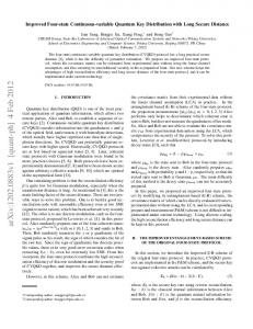
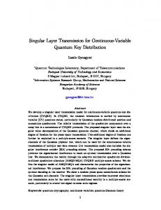
device, we are able to amplify one of the modes from a two-mode squeezed state (twin beams) in order to make quantum clones. This represents an important step towards quantum cloning of an entangled state. As a first step in characterizing the behavior of the 4WM-based amplifier we measure the NF as a function of gain when the input is a coherent state and compare this to the quantum-noise-limited case. Following the method of Ref. [17] the input state is a 50 µW shot noise limited beam amplitude-modulated at 1 MHz to provide a signal about 20 dB above the noise. The test configuration consists of a 85 Rb vapor cell with a strong pump injected along with the modulated input signal at a slight angle. There are two input ports, either of which can be seeded while the other is left with vacuum input. Depending on which port is seeded, the signal is either upshifted or downshifted ≈3 GHz from the pump, which is tuned near the D1 line (Fig. 1A). Due to 4WM, the input is amplified, while a second output is produced at the unseeded frequency [18, 19]. When only one input port is seeded the process is phase-insensitive [20], as will be shown later. We call the frequency-upshifted beam the conjugate, and the frequency-downshifted beam the probe. The NF was calculated by comparing the SNR, which was measured with a radio frequency spectrum analyzer centered at 1 MHz, before and after the cell for various gains. The input SNR was measured by bypassing the vapor cell using flip mirrors (Fig. 1B), so that it would not be underestimated due to losses on the vapor cell windows. Figure 1C shows the NF as a function of gain. The performance of the amplifier can be changed using different methods. The temperature of the vapor cell controls the Rb number density, while the detuning of the pump from the D1 line along with the frequency difference between the pump and signal change the strength of the nonlinearity. Only some combinations of temperature and detunings result in a near-ideal NF. In Fig. 1C the gain was controlled by changing the pump detuning while maintaining the difference between pump and signal frequencies at 3036 MHz. The gain increases as the pump
2
B)
A)
SA
0.8 GHz
C
P
Pr
F=3 F=2
P
flip mirrors signal
3 GHz
P
Rb
noise figure
C) 1.0
Probe Conjugate
0.8 0.6 0.4 0.2 0.0 1
2
3
gain
4
5
6
FIG. 1: (color online) A) Energy level diagram for the 4WM process. Pr: probe; C: conjugate; P: pump. B) The configuration used to verify the noise figure of the amplifier. SA: spectrum analyzer. The dotted (orange) line represents the unused ancillary beam generated by the amplifier. C) The noise figure of the amplifier for various gains. The solid (blue) curve represents the ideal noise figure. The dashed (purple) curve shows the noise figure that would be measured if an ideal amplifier were monitored with a 95% efficient detector. The dotted line shows the change in gain as the pump frequency is moved from blue to red through the gain maximum for amplification of the probe beam.
frequency comes closer to the atomic resonance. The NF when the probe frequency is seeded (triangles) follows slightly below the ideal curve as the pump is tuned from the blue toward the maximum of the 4WM gain. As the pump is tuned red of the gain maximum the NF degrades because of absorption of the probe at these frequencies. The total scanning range was ≈1 GHz centered at the 4WM gain maximum. The circles represent the NF when the conjugate frequency is seeded and the pump is tuned from the blue to near the gain maximum. The conjugate NF is in general better than the probe since it experiences less absorption over a wider frequency range. The cell temperature was 110 ◦ C for all measurements. The detector efficiency was ≈95%. Imperfect detectors cause an overestimation of the NF since they underestimate the noise added by the amplifier [17]. The dashed curve in Fig. 1C shows the ideal NF rescaled in order to account for detector efficiency, η: NF = G/(2ηG−2η+1). Note that the data represent the “as built” behavior of the actual device without any corrections for imperfections. In particular, we do not correct for losses on the cell windows (≈2% per window) or polarizer (≈1%). This study of coherent state amplification establishes
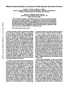
that the 4WM amplifier represents a practical approximation to an ideal quantum-limited amplifier for Gaussian CV states. We now explore the action of this amplifier on non-classical states; in particular we use it to amplify one mode of a two-mode squeezed state. We study the cloning operation on one half of an entangled state by using a configuration in which the amplifier is followed by a variable attenuator, whose output simulates one of the outputs of a beam splitter. By setting the gain-attenuation product to one we can study a range of cloning configurations, including asymetric clones (when clones have unequal intensities) and the usual case with an amplifier gain of 2 followed by a 50% beamsplitter (when there are two clones with equal intensity). The last case is an implementation of the “local e-cloner” discussed theoretically in Ref. [21]. First, an initial vacuum two-mode squeezed state with 4.3(2) dB (all uncertainties are combined statistical and systematic) of noise reduction (see Fig. 3) is generated using 4WM starting with vacuum input in both ports [20]. As shown in Fig. 2, after the first cell the two output modes are separated. The conjugate is passed along with the pump beam through a 4f imaging system and input into a second 85 Rb cell which acts as the amplifier. The amplifier gain is controlled by adjusting the temperature of the second cell, since the detunings of the various beams are necessarily the same in both cells for our experimental setup. HJ
+ g
SA EPR generation
P
HD
LO Pr LO C
Amplification
PBS
ND filter
UA
FIG. 2: (color online) Experimental setup: C: conjugate beam; Pr: probe beam; SA: spectrum analyzer; PBS: polarizing beam splitter; g: electronic attenuator; HJ: hybrid junction; LO: local oscillator; HD: homodyne detector; UA: unused ancilla. The LOs follow almost identical beampaths to those of the EPR beams (dashed lines).
Characterization of the entanglement relies on meaˆ and phase, Yˆ , quadrasurements of the amplitude, X, tures of each beam. The quadratures are defined such that their variances for coherent states (called the stan-
3 attenuator after the conjugate HD (Fig. 2). 12.5 10.0
noise power (dBm)
dard quantum limit, or SQL) are 1. Homodyne detection, which requires mode matching the signal to a bright local oscillator (LO), is used to make the required measurements. To generate the LOs an identical 4WM process is used. This process has its own pump and is spatially separated from the twin beam generation but takes place in the same cell. It is seeded with a small input (≈ 200µW), resulting in bright beams. The conjugate’s LO (along with its own pump) is passed along with the conjugate and its pump through the 4f imaging system, is amplified in the second cell, and is attenuated afterwards by a neutral density (ND) filter. The pumps for both LO and twin beams have equal powers. Generating LOs in this way ensures that they have the same frequencies and wavefronts as the twin beams [20]. Passing through the ND filter keeps the overall gain-loss product of the conjugate LO at unity, thus the conjugate’s homodyne detector (HD) gain is constant. ˆ and Yˆ , one can construct the joint quadraUsing X √ √ ˆ ˆ1 − gX ˆ 2 )/ 2 and Yˆ+ = (Yˆ1 + g Yˆ2 )/ 2 tures X− = (X needed to calculate two measures of entanglement: the inseparability [22, 23] and the extent to which our state satisfies the Einstein-Podolsky-Rosen (EPR) paradox [24]. To be applicable the two measures require the state to be Gaussian [25]. The coefficient g is a parameter which is used to optimize the entanglement measurement. The inseparability criterion states that a necessary and sufficient condition for entanglement is that the sum of the joint quadrature operator variances satisfies: ˆ − )2 + (∆Yˆ+ )2 < (1 + g 2 ) for some g. Adjusting g (∆X amounts to a local Bogoliubov transformation of the uncertainty ellipses in phase space [22], and can be done in practice by electronically attenuating the signal from one of the homodyne detectors, as shown in Fig. 2. We tune g to minimize the joint quadrature variances. When the variances are normalized to the corresponding SQLs, the ˆ− )2 + (∆Yˆ+ )2 < 2. criterion becomes I ≡ (∆X N N The EPR criterion indicates the extent to which a measurement on one system (an optical mode) can give information about the state of the other system [24]. The EPR parameter is obtained by measuring the conditional variances: Eij ≡ VXi |Xj · VYi |Yj , where VX(Y )i |X(Y )j is the variance of a prediction on a quadrature of system i, having performed a measurement on system j. The criterion states that two systems are EPR-entangled when Eij < 1. One can also construct the inequality by making a measurement on system i and predicting the result for system j instead: Eji = VXj |Xi · VYj |Yi . In general Eji 6= Eij [26]. The VX(Y )i |X(Y )j are the joint quadrature variances normalized to the shot noise of the system ˆ1 − g X ˆ 2 )2 |g=gmin , where being estimated: VX1 |X2 = ∆(X gmin minimizes that variance [24], ensuring that the joint quadrature measurement is done in the correct basis [26]. ˆ1 − gX ˆ 2 )2 is different from its The g that minimizes ∆(X value when I is optimized. In both cases, the g values were found empirically by adjusting a variable electronic
7.5 5.0 2.5 0.0 -2.5 -5.0
0.0
0.3
0.6 0.0 time (s)
0.3
0.6
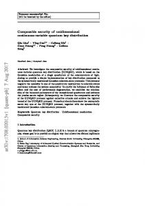
FIG. 3: (color online) Squeezing traces at 1 MHz (zero span, RBW: 10kHz, VBW: 300Hz) for the amplitude difference and phase sum quadratures, normalized to the shot noise level, for two different amplifier gains as a function of HD phase. The HD phases are scanned synchronously in time so that they always measure the same quadratures for each beam at a given time [20]. The traces on the left show the squeezing level with the amplifier turned off and no ND filter in the conjugate beam path. The right traces show the squeezing when the amplifier gain is ≈1.8. The minima of the solid 2 ˆ− (blue) traces represent ∆X , while the minima of the dashed 2 ˆ (red) traces represent ∆Y+ .
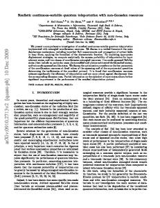
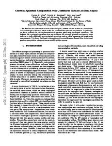
Figure 3, left, shows the reference squeezing level when the amplifier is turned off, and no ND filter is in the conjugate beam path (the losses on the vapor cell windows still affect the observed squeezing). The minima of each curve represent the amplitude difference, X− , and phase sum, Y+ , joint quadrature noises respectively. After the first cell, both joint quadratures are squeezed equally and both exhibit the same amount of antisqueezing, indicating the initial twin beam generation process is phase insensitive. The right traces in Fig. 3 show the squeezing level when the gain of the amplifier is set to 1.8 and the attenuator transmits 56% of the light. The noise of both squeezed and antisqueezed quadratures remains at equal levels, confirming that the amplification process is also phase insensitive. Figure 4 shows E12 and I as a function of gain, where the “12” subscript represents a measurement on the conjugate beam being used to predict the result of a measurement on the probe beam. One noteworthy aspect of Fig. 4 is that the state remains inseparable (I < 2) for a gain of up to 2.8. It is evident from the plot that a non-negligible degree of entanglement still remains for a gain of 2 followed by 50% attenuation. In other words, after symmetrically cloning one mode from a two-mode squeezed state, the clones are entangled with the other unmodified mode from the original state. The EPR parameter reaches its limit of 1 with gain more quickly than the inseparability. Nonetheless, up to a gain of 1.2, EPR correlations are maintained. Given that the amplifier adds excess noise to the conjugate,
4 3.0 E12 I
2.5
E 12, I
2.0 1.5 1.0 0.5 0.0 1.0
1.5
2.0 gain
2.5
3.0
FIG. 4: (color online) E12 and I as a function of gain. The gain-loss product for each point was unity. The dash-dotted and dashed horizontal lines represent the upper bounds to the inseparability and EPR criteria, respectively. The solid curve shows the theoretical predictions for the inseparability, calculated from the total Hamiltonian of the amplifierbeamsplitter-detector system. The dotted curve shows the theoretical prediction for the EPR parameter, calculated following the method in [25]. The error bars are propagated from a combined statistical and systematic uncertainty of 0.2 dB in the noise reduction measurements. The disagreement between E12 and the theory is due to experimental difficulty in ascertaining the purity of the output state.
cal modes, and is reminiscent of the scheme for multipartite entanglement proposed by Ferraro, et al. [27], while somewhat different from the multipartite entanglement schemes proposed by Pfister, et al. [28]. An interesting question is whether the method described here is the best way to maintain entanglement while cloning a single mode. It has been established that universal amplifiers maintain the best fidelity for Gaussian states, but how fidelity relates to entanglement when cloning only one mode is an open question. Questions like these, along with the multiple cloning ability of the device suggest many new avenues of exploration and potential uses for quantum-noise-limited amplifiers based on 4WM. Further, the ability to amplify multiple spatial modes in parallel [20] can lead to the cloning of quantum images. R. C. P. was supported by a grant from the IC postdoctoral research program.
∗ †
which unbalances the variances, the two EPR parameters are not symmetric (E12 6= E21 ). Using the probe to infer a property of the conjugate would be less successful, since only a portion of the total conjugate noise is correlated with the probe noise. The E12 we have measured here represents the best case scenario. The EPR parameter suffers much more from increasing gain than the inseparability because it is more sensitive to the degree to which the state is mixed. Inseparability describes how separable the density matrices of the two susbsystems are, immaterial of whether the total density matrix represents a pure state. As the gain increases and the ND filter transmission decreases, more and more excess noise mixes with our original input, resulting in a mixed state. Because of this, we expect the EPR to degrade more quickly than the inseparability. The excess noise added by the amplifier can be thought of as the result of tracing over the unused ancilla, which is entangled with the amplified conjugate. The excess noise increases with gain, which leads to decreased quantum correlations, as shown in Fig. 4. The quantum entanglement is not totally lost, however. By measuring the ancillary beam we could extract more information about the entanglement between it and the cloned modes. In this paper we have demonstrated the viability of 4WM in an atomic vapor as a nearly quantum-noiselimited amplifier. We have demonstrated the ability to locally clone one mode from a two-mode squeezed state and maintain entanglement. The resulting state would have entanglement distributed among three opti-
[1] [2] [3] [4] [5] [6] [7] [8] [9] [10] [11] [12] [13] [14] [15] [16] [17] [18] [19] [20] [21] [22] [23] [24] [25] [26] [27] [28]
Electronic address:
[email protected] Electronic address:
[email protected] C. M. Caves, Phys. Rev. D 26, 1817 (1982). S. L. Braunstein and P. van Loock, Rev. Mod. Phys. 77, 513 (2005). S. Fossier et al., arXiv:quant-ph/0812.4314v1 (2008). A. Messikh et al., J. Phys. B 40, 1153 (2007). N. J. Cerf, A. Ipe, and X. Rottenberg, Phys. Rev. Lett. 85, 1754 (2000). S. L. Braunstein et al., Phys. Rev. Lett. 86, 4938 (2001). J. Fiur´ aˇsek, Phys. Rev. Lett. 86, 4942 (2001). W. K. Wootters and W. H. Zurek, Nature 299, 802 (1982). D. Dieks, Phys. Lett. 92A, 271 (1982). G. C. Ghirardi and T. Weber, Nuovo Cimento Soc. Ital. Fis. 78, 9 (1983). H. P. Yuen, Phys. Lett. 113A, 405 (1986). V. Buˇzek and M. Hillery, Phys. Rev. A 54, 1844 (1996). J. A. Levenson et al., J. Opt. Soc. Am. B 10, 2233 (1993). Z. Y. Ou, S. F. Pereira, and H. J. Kimble, Phys. Rev. Lett. 70, 3239 (1993). V. Josse et al., Phys. Rev. Lett. 96, 163602 (2006). U. L. Andersen, V. Josse, and G. Leuchs, Phys. Rev. Lett. 94, 240503 (2005). U. L. Anderson and G. Leuchs, J. Mod. Opt. 54, 2351 (2007). C. F. McCormick et al., Opt. Lett. 32, 178 (2007). C. F. McCormick et al., Phys. Rev. A 78, 043816 (2008). V. Boyer et al., Science 321, 544 (2008). C. Weedbrook et al., Phys. Rev. A 77, 052313 (2008). L.-M. Duan et al., Phys. Rev. Lett. 84, 2722 (2000). R. Simon, Phys. Rev. Lett. 84, 2726 (2000). M. D. Reid, Phys. Rev. A 40, 913 (1989). A. M. Marino et al., Nature 457 859 (2009). W. P. Bowen et al., Phys. Rev. A 69, 012304 (2004). A. Ferraro et al., J. Opt. Soc. Am. B 21 1241 (2004). O. Pfister, et al., Phys. Rev. A 70 020302 2004.