Email: {liu nan, kschong, wgho, ebhgwee, ejschang}@ntu.edu.sg. AbstractâIn ... Verilog netlist into a direct circuit graph, allowing us to model. QDI pipelines for ...
Low Normalized Energy Derivation Asynchronous Circuit Synthesis Flow through Fork-Join Slack Matching for Cryptographic Applications Nan Liu, Kwen-Siong Chong, Weng-Geng Ho, Bah-Hwee Gwee and Joseph S. Chang Nanyang Technological University, 50 Nanyang Avenue, Singapore 639798 Email: {liu nan, kschong, wgho, ebhgwee, ejschang}@ntu.edu.sg Abstract—In this paper, an automatic synthesis flow of asynchronous (async) Quasi-Delay-Insensitive (QDI) circuits for cryptographic applications is presented. The synthesis flow accepts Verilog netlists as primary inputs, in part leverages on commercial electronic design automation tools for synthesis and verifications, and relies heavily on the proposed translation processes for async netlist conversion and optimization. Particularly, a three-step synchronous-to-asynchronous-direct-translation (SADT) process is proposed. The first step is to translate a Verilog netlist into a direct circuit graph, allowing us to model QDI pipelines for performance analysis based on the same netlist function. Second, graph coarsening in combination with dynamic programing is adopted to analyze the fork-join slack matching of the QDI pipelines, aiming to balance the pipeline depths in any fork-join pipelines to optimize the system performance, and to reduce energy variations of the overall pipelines to against power-analysis-attack. The last step is to insert async local controllers/gates to ensure the async circuits consistent with QDI protocol, hence enhancing its timing robustness to accommodate Process-Voltage-Temperature variations. We show that, on the basis of simulations on the ISCAS benchmark circuits, the QDI circuits based on our proposed automatic synthesis flow are on average 20% faster and feature 30% less normalized energy derivations than un-optimized circuits.
I.
I NTRODUCTION
Asynchronous (async) approaches provide a potential solution to mitigate the problems of increasing process-voltagetemperature (PVT) variations in integrated circuits (ICs), especially when the feature size of fabrication processes continues to scale downwards. Of various realization methods of the asynchronous approach, the Quasi-Delay-Insensitive (QDI) [1] realization method, as opposed to other Bundled-Data and Speed-Independent realization methods, has been widely recognized as the most practical option [2] to accommodate PVT variations. The basic premise is that circuits based on the QDI realization method can innately accommodate any timing variations [3] due to PVT variations, hence without affecting the functionality of the circuits. This is because QDI circuits adopt 1-of-N -rail logic (e.g. typically N =2, equivalent to dualrail logic) such that every transition of wires contains timing information to be properly acknowledged. One drawback of the QDI circuits is high hardware overhead, however, for some niche applications such as defense and security applications, the robustness/reliability issue is more important than the overhead issue. This paper addresses the QDI realization methodology for security applications, particularly for our cryptographic applications which not only feature high robustness, but are also countermeasure against power-analysis-attack [4].
c 978-3-9815370-7-9/DATE16/ �2016 EDAA
The async approach, including the QDI realization method, has previously been applied to cryptographic applications [5] countermeasure against power-analysis-attack. The key idea of using async approach is to randomize the circuit operations in time dimension, making the power-analysis-attack difficult. However, there still have several challenges to make such approach practical. First, the data dependency [4] of async circuits remains the possible weakest link to decipher the key (or password) in cryptographic applications has been previously investigated [5]. To mitigate the data dependency, reported techniques include making each dual-rail (Wave Dynamic Differential Logic) circuit [6] to dissipate similar energy for all data inputs. Nevertheless, from a system perspective, the operation dependency remains in varied various task operations, causing energy variations and hence possibly leaking the information. Second, the Electronic Design Automation (EDA) tools for async approach remain unmature. Several research projects have focused on EDA tools for async designs. However, some tools, which adopt in-house specification languages, are incompatible to the well developed synchronous design flow; these tools include Balsa using Communicating Sequential Processes (CSP) [7], Martin’s Communicating Hardware Processes (CHP) [1], and Tangram [8] using CSP-like programming language. The using of these esoteric languages enforces async designers into an unfamiliar programming, and the rewriting of existing specifications is unrealistic for large and practical designs. Petrify [9] suffers from reachability problem which is exponential time-hard and exponential space-hard. A relatively async EDA method is to use a Synchronous-to-Asynchronous-Direct-Translation (SADT) methodology [10]–[14], such as De-synchronization [10], Null convention logic (NCL) [11], [12], Weaver [13] and Proteus [14]. De-synchronization imposes timing assumption to automatically convert a synchronous netlist to an async counterpart. [11], [12] adopts NCL logic family for logic synthesis and optimization, but the resultant overheads (and speed penalty) are large. Weaver and Proteus target on high performance QDI pipeline realization. Nevertheless, most of these EDA tools are either ad-hoc solutions which do not support automatic synthesis, and none of them are exclusively developed for cryptographic applications, hence their efficacy remains unclear. In this paper, we present an automatic synthesis flow of async QDI circuits for cryptographic applications. Particularly, we propose a three-step SADT process. The first step is to translate a Verilog netlist into directed graphs. Second,
850
we adopt graph coarsening in combination with dynamic programming to analyze the fork-join slack matching of the QDI pipelines (see later), and further to adjust the un-balance re-converge fork-join pipelines. The objective here serves two folds: (i) we aim to balance the pipeline depths in any forkjoin pipelines to optimize the system performance, and (ii) the balanced fork-join pipelines reduce energy variations, hence increasing resistance to power-analysis-attack. The last step is to insert async local controllers/gates to make the async circuits consistent with QDI protocol. Although our SADT process is somewhat similar to the reported Weaver and Proteus, our second step is novel in view of cryptographic applications. The rest of paper is organized as follows. Section II describes the automatic synthesis flow of async QDI circuits, including our proposed SADT process. Section III presents the experiment results, and conclusions are given in Section IV. II.
P ROPOSED S ECURED C IRCUIT S YNTHESIS F LOW
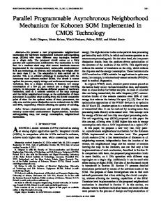
In this section, we first present in Fig. 1 the proposed automatic synthesis flow for cryptographic async QDI circuits. In Fig. 1, the processes in the white boxes are the standard processes from commercial EDA tools, including Behavior Modeling using Verilog, Synthesis using Synopsys’s Design Compiler, and Placement & Routing using Cadence’s First Encounter. The shaded box depicts our proposed three-step SADT process to generate async QDI netlists; for brevity, we term our tool as Graph-based Translation Optimization (GTO) for this process. We now describe our SADT process in details.
1) 2)
Egw = {(u, v|u ∈ Vg , v ∈ Vw )}, direct edges from u to v or v to u; Eow = {(z, v|z ∈ Vo , v ∈ Vw )}, direct edges from z to v or v to z.
The constructed graph model will be used directly as the foundation for the SADT process, further analyzing the performance of async QDI systems. B. Slack Matching Slack matching [15], [16] is unique to async designs that have slack elasticity [15] property. It is applied to reduce or remove the stalls generated from unbalanced fork-join pipelines or short cycles in a pipelined async circuit by inserting pipeline buffers into communication channel without affecting the correctness of the designs. In this subsection, a graph coarsening in combination with dynamic programming method will be introduced. 1) Fork-Join Matching Graph Coarsening: The proposed fork-join matching graph coarsening is accomplished in two phases. First, an agglomeration heuristic produces a clustering of the fork-join set. Later with this clustering, the next coarsening level is built by contracting all vertices of each cluster into a coarse-graph vertex. Each merge decreases the number of fork-join stages. The coarsening process can reduce the size and complexity of graph, as well as the complexity of systems. Fig. 2 depicts a simple nested re-converge fork-join stage.
Fig. 2: A simple nested re-converge fork-join stage. 2) Graph Coarsening in Combination with Dynamic Programming Optimization: The energy variation and performance of async QDI circuits can be improved by inserting the pipeline buffers to balance the re-converge fork-join stages. In this subsection, the graph coarsening in combination with dynamic programming algorithm is presented.
Fig. 1: Proposed secured circuit synthesis flow. A. System Modeling To model synchronous systems, the Verilog gate-level netlist is used to construct a set of direct circuit graphs {G1 , G2 , ..., Gn }, each graph matches one functional module. For example, consider a system that contains one multiplier and one accumulator where the accumulator further contains an adder. In this case, four graphs will be constructed to represent this system: multiplier, accumulator, adder, and top module, respectively. Each graph Gi (V, E)(1 ≤ i ≤ n) is defined as follows: the vertex set is defined as V = Vg ∪ Vn ∪ Vw , where Vg corresponds to the set of gates in the netlist; Vw is the set of wires in the netlist, and Vo is the set of input/output signals. The edge set is defined as E = Egw ∪ Eow , for there is no edges between Vg and Vo , where
Problem Formulation: The fork-join slack matching problem is modeled as sequential decision stages S = S1 , S2 , ..., Sk , the decision performance variable P = P1 , P2 , ..., Pk and power consumption variable E = E1 , E2 , ..., Ek (1 ≤ k ≤ n). 1). At the beginning of stage Sn , the stage is in state Sn−1 ; 2). The contribution to the objective function depends on Sn , Pn , and En ; 3). Sn depends on Sn−1 , Pn−1 , and En−1 . Balanced based dynamic programming optimization for energy variation and performance: The dynamic programming optimization functions are as follows: Obj(Sn ) =M in{α[P1 (d1 , S1 ) + ... + Pn−1 (dn−1 , Sn−1 )+ Pn (dn , Sn )] + β[E1 (cd1 .S1 ) + ... + En−1 (cdn−1 , Sn−1 ) + En (cdn , Sn )]} n n � � =M in[α Pn (dn , Sn ) + β En (cdn , Sn−1 )] 1
1
Sn =fn−1 {α[Pn−1 (dn−1 , Sn−1 ] + β[En−1 (cdn , Sn−1 )]}
2016 Design, Automation & Test in Europe Conference & Exhibition (DATE)
851
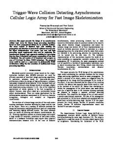
Fig. 3: Graph coarsening in combination with dynamic programming optimization.
where Obj(Sn ) is the target optimized cycle time of all the subsequent decisions, S1 means the innermost fork-join stage; P1 and E1 are the innermost fork-join cycle time and innermost fork-join power consumption, respectively. Dn is the number of inserted pipeline buffers at Sn , and dn ∈ Dn . c is the power consumption for each buffer. α, β are user defined function to adjust the tradeoff between performance and power consumption. The new state at the beginning of Sn determined by Sn−1 is fn−1 {α[Pn−1 (dn−1 , Sn−1 )] + β[En−1 (cdn , Sn−1 )]}. Fig. 3 shows the optimization process of graph coarsening in combination with dynamic programming. At Stage 1, one pipeline buffer is inserted to the innermost fork-join stage F J1, followed by the cluster of 6 vertices, F J1 becomes a vertex of F J2 (square). Then, for Stage 2, the balanced F J2 will be clustered without any pipeline buffer inserted, and F J2 becomes a vertex of F J3 (rhombus). At last, Stage 3 is the cluster of F J3 with one pipeline buffer inserted. The balanced nested fork-join stages will be coarsening to only one pipeline stage (pentagon). All of the additional pipeline buffers are inserted to the circuits by an un-coarsening process after decision. C. Graph based Vertices Translation The synchronous circuits with single rail (SR) data wires are substituted by channels generally comprising dual rail (DR) data wires and acknowledge (ack) wires in this step. The ack wires are used for handshaking the connecting pipelines. The details of SADT process rules and how to replace the synchronous gates by async pipeline stages by vertices translation are similar to [13], [14]. Async QDI systems with balanced fork-join pipeline are obtained after these steps.
III.
E XPERIMENTAL R ESULTS
To evaluate the performance and the energy variation of various pipelines, we first design a simple original 2-path forkjoin pipeline using WCHB [17], where the short path has only one stage and the long path has stages from n = 2 to n = 10; this original fork-join pipeline is termed as “Orig.” pipeline. In our comparison, we also design another two improved versions of the fork-join pipelines. The first improved version is called “+1HB” pipeline where the short path is added with one half buffer (HB). The second improved version is called “Bal.” pipeline where the short path is added with HBs so that the short and the long paths have the same (balanced) stages. Table I tabulates the cycle time, maximum energy, minimum energy, Normalized Energy Derivation (NED) and Normalized Standard Deviation (NSD) [6] for various fork-join pipelines. As expected, the closer the number of stages in the short and long paths, the faster the cycle time, as shown in columns 2, 3, and 4. Similarly, consider the energy variations where NED and NSD are used as figures-of-merit, we show that adding HBs (to make the short and long path to have similar stages) does help reduce energy variations. NED and NSD are shown from columns 11 to 16, we can obtain that adding one HB to un-balanced path will improve NED (14%) and NSD (16%) of the circuits as shown in columns 12 and 15. Should the Bal. pipelines be considered, averaging, they improve NED and NSD by 28% and 29% respectively. SADT Performance Evaluation: The evaluation makes use of the characteristics of both synchronous and async systems, and is especially effective to evaluate the performance of
TABLE I: The comparison of async Fork-Join Pipelines embodying different number of Half Buffers (HBs). Average Delay (ns) Orig. +1HB Bal. 1.57 − 1.32 1.96 1.41 1.37 2.80 1.66 1.34 2.70 1.93 1.34 3.22 2.14 1.39 3.61 2.38 1.39 4.01 2.66 1.65 4.38 2.89 1.55 4.78 3.22 1.42 number of HB
Circuit n=2 n=3 n=4 n=5 n=6 n=7 n=8 n=9 n=10 *n:
852
Max Energy (fJ) Orig. +1HB Bal. 237.51 − 263.79 292.01 307.02 358.89 343.43 379.56 436.84 394.56 438.78 516.6 464.89 489.66 626.07 517.14 539.93 718.42 570.36 599.76 783.13 623.39 648.61 898.64 675.85 719.71 875.20
Min Energy (fJ) Orig. +1HB Bal. 212.48 − 240.04 263.56 291.94 327.57 297.85 345.64 399.67 345.24 394.20 472.27 417.56 442.40 581.78 465.25 490.08 669.15 513.83 547.13 750.48 561.36 597.57 840.45 608.14 660.45 820.32 Avg.
Orig. 10.5 9.7 13.2 12.5 10.2 10.0 9.9 9.9 10.0 1
NED (%) +1HB − 9.3 8.9 10.6 9.7 9.2 8.8 7.9 8.2 0.86
Bal. 9.0 8.7 8.5 8.6 7.1 6.9 7.5 6.5 6.2 0.72
Orig. 5.6 5.1 7.1 6.7 5.4 5.3 5.2 5.2 5.3 1
2016 Design, Automation & Test in Europe Conference & Exhibition (DATE)
NSD (%) +1HB − 4.9 4.7 5.4 5.1 4.8 4.6 4.0 4.3 0.84
Bal. 4.7 4.6 4.4 4.5 3.7 3.6 3.9 3.4 3.2 0.71
async systems obtained from SADT process. The performance evaluation contains two parts, the first part is based on full buffer channel net (FBCN) [2] model to calculate the forkjoin part of the circuits, and Karp’s algorithm [19] to calculate the linear and loop part. Here, C-muller is not taken into consideration, for the number of C-muller is not changed during the optimization procedure. For simplicity, the local cycle time is set to 5 time units, the forward time of each pipeline stage is 1 time unit and the backward time is 4 time unit, the power consumption of HBs are 70% of the pipeline stages, the balanced re-converge fork-join stage cycle time is equal to local cycle time. The proposed GTO is implemented in Java, and we further evaluate our synthesis flow by using ISCAS’85 and ISCAS’89 [18] benchmark circuits. These circuits are modeled in Verilog and synthesized using a 65nm CMOS library. TABLE II: Performance Optimization for proposed Async QDI circuits Bench. c432 c880 c1355 c1908 c3540 s298 s526 s832 s1196 s1488 s5378 s13207 *ISCAS
#G 160 383 546 880 1669 75 141 262 388 550 1004 2027 85: cxx;
#I #O 36 7 60 26 41 32 33 25 50 22 3 6 3 6 18 19 14 14 8 19 35 49 36 39 ISCAS 89: sxx
τ 135 75 51.6 42.4 116 64 235 265.3 73 55 373.7 855
τo 115 75 50 40 110 60 125 145 50 35 270 645 Avg.
Imp.(%) 14.8 0 3.1 5.7 5.2 6.3 46.8 45.3 31.5 36.3 27.9 24.6 20.6
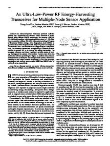
The results are shown in Table II. Columns 2, 3, and 4 are the number of gates (#G), inputs (#I), and outputs (#O) of the benchmark, respectively. Columns 5 and 6 are the original cycle time (τ ) and the optimized cycle time (τo ), respectively. Column 7 is the percentage of improved cycle time (Imp.%). As demonstrated by experimental results, our proposed approach can achieve on average about 20.6% optimization for performance, with insertion of 27 HBs on average. The netlist is synthesized by design compiler on the basis of synchronous circuits so that the sequential circuits with clock signal are affected more than combinational circuits, and the unbalanced re-converge fork-join stages often have a big difference in sequential circuits, the performance is improved by 31.2% on average with 13.1% power overhead; The performance of combinational circuits is improved by 7.2% on average with 2.8% power overhead. From Fig. 4, we also make the following remarks. First, when the performance improvement reaches its local maximum, adding more HBs not only reduce the performance but also increase power consumption. Second, the combinational logic has little room to improve performance (up to 15%). On the other hand, the sequential logic features higher improve performance (with the peak of 47%). IV.
C ONCLUSIONS AND F UTURE W ORK
In this paper, an automatic synthesis flow of async QDI circuits for cryptographic applications, and a three-step SADT process have been proposed. Particular, for async QDI circuits, the security by adjusting pipeline stages is improved
Fig. 4: Performance and Power Tradeoff.
and demonstrated, the QDI circuits based on our automatic synthesis flow were on average 20% faster and feature 30% less NED than original un-optimized circuits. Cryptographic circuits will be taken into consideration in future work. ACKNOWLEDGMENT This research work was supported by Agency for Science, Technology and Research, Singapore, under SERC 2013 Public Sector Research Funding, Grant No: SERC1321202098. R EFERENCES [1]
A. J. Martin, “Compiling communicating processes into delay insensitivity VLSI circuits,” Distributed Computing, vol. 1, no. 4, pp. 226-234, 1986.
[2]
P. A. Beerel, et al., “A Designer’s Guide to Asynchronous VLSI,” Cambridge University Press, 2010. K.-S. Chong, et al., “Energy-efficient synchronous- logic and asynchronous-logic FFT/IFFT processors,” IEEE JSSC, vol. 42, no. 9, pp. 2034- 2045, Sep. 2007. S. mangard, E. Oswald, and T. Popp,“Power Analysis Attacks, Revealing the Secrets of Smart Cards,” Springer, 2007.
[3] [4] [5] [6] [7] [8] [9]
[10]
[11] [12] [13] [14] [15] [16] [17] [18] [19]
G. F. Bouesse, et al., “DPA on Quasi Delay Insensitive Asynchronous Circuits: Formalization and Improvement,” in Proc. DATE, pp. 424-429, 2005. K. Tiri and I. Verbauwhede, “A Logic Level Design Methodology for a Secure DPA Resistant ASIC or FPGA Implementation,” In Proc. DATE, pp. 246-251, 2004. C. A. R. Hoare, “Communicating Sequential Processes” , Communactions of ACM, vol. 21, no.8, pp. 666-677, Aug. 1978. J. Kessels and A. Peeters, “The Tangram framework: asynchronous circuits for low power,” in Proc. ASP-DAC, pp. 255-260, 2001. J. Cortadella, et al., “Petrify: a tool for manipulating concurrent specifications and synthesis of asynchronous controllers,” IEICE Trans. Inf.& Syst., vol. 3, pp. 315325, 1997. J. Cortadella, et al., “Desynchronization: Synthesis of asynchronous circuits from synchronous specifications,” IEEE TCAD, vol. 25, no. 10, pp. 1904-1921, Oct. 2006. M. Ligthart, et al., “Asynchronous design using commercial HDL synthesis tools,” in Proc. ASYNC, pp. 114-125, 2000. R. Zhou, et al., “Synthesis of asynchronous QDI circuits using synchronous coding specifications,” in Proc. ISCAS, pp. 153-156, 2014. A. Smirnov, et al., “Automated pipelining in ASIC synthesis methodology: gate transfer level,” in International Workshop on Logic and Synthesis, 2004. P. A. Beerel, et al., “Proteus: An ASIC Flow for GHz Asynchronous Designs,” IEEE Design & Test of Computers, vol. 28, no.5, pp. 36-51, 2011. P. Prakash, and A. J. Martin, “Slack matching quasi delay-insensitive circuits,” in Proc. ASYNC, pp. 194-204, 2006. M. Najibi, and P. A. Beerel, “Slack matching mode-based asynchronous circuits for average case performance,” in Proc. ICCAD, pp. 219- 225, 2013. Y. Thonnart, et al., “A pseudo-synchronous implementation flow for WCHB QDI asynchronous circuits,” in Proc. ASYNC, pp. 73-80, 2012. [Online] http://www.pld.ttu.ee/∼maksim/benchmarks. R. M. Karp, “A characterization of the minimumcycle mean in a digraph,” Discrete Math., vol. 23, pp 309-311, 1978.
2016 Design, Automation & Test in Europe Conference & Exhibition (DATE)
853