A distributed, low power, wireless, integrated microsensor. (LWIM) technology can .... output power amplifiers, operating at 1 - 10mW RF power, and low duty cycle .... Signal Processing, New Jersey: Prentice-Hall, 1994, pp 53-. 124. [5] D. B ...
Low Power Systems for Wireless Microsensors K. Bult, A. Burstein, D. Chang, M. Dong, M. Fielding, E. Kruglick, J. Ho, F. Lin, T. H. Lin, W. J. Kaiser, H. Marcy*, R. Mukai, P. Nelson, F. L. Newburg, K. S. J. Pister, G. Pottie, H. Sanchez, K. Sohrabi, O. M Stafsudd, K. B. Tan, G. Yung, S. Xue, and J. Yao** UCLA Electrical Engineering Department Los Angeles, CA and *Rockwell Science Center Thousand Oaks California Abstract -- Low power wireless sensor networks provide a new monitoring and control capability for civil and military applications in transportation, manufacturing, biomedical, environmental management, and safety and security systems. Wireless microsensor network nodes, operating at average and peak power levels constrained by compact power sources, offer a range of important challenges for low power methods. This paper reports advances in low power systems spanning network design, through power management, low power mixed signal circuits, and highly integrated RF network interfaces. Particular attention is focused on methods for low power RF receiver systems.
I. Introduction A distributed, low power, wireless, integrated microsensor (LWIM) technology can provide new product opportunities and new system capabilities. The development and deployment of distributed monitoring and controls has been hindered in the past by the requirements of complex installation and communication network requirements. Conventional distributed sensors have required cable interface, and therefore, extensive modification to structures for sensor installation. Low power systems offer a new approach for distributed MEMS based on a wireless sensor infrastructure. A wireless microsensor network may be distributed rapidly and without modification to large structures and systems. Also, wireless sensors may be applied in areas where volume and mass constraints limit the application of conventional wireline interface sensors. The wireless network architecture allows microsensor nodes to be deployed in a broad spectrum of military applications ranging from battlefield perimeter security and shoreline reconnaissance to personnel health monitoring. Wireless microsensor nodes may also be applied to rotating machinery without the complex slip-ring
ISLPED 1996 Monterey CA USA 0-7803-3571-8/96/$5.00 1996
systems that would normally be required for a conventional sensor electrical interface. A set of unique requirements exist for distributed wireless microsensor networks. The individual low cost sensor nodes must be 1) reconfigurable by their base station, 2) autonomous to permit local control of operation and power management, 3) self-monitoring for reliability, 4) power efficient for long term operation, and 5) must incorporate diverse sensor capability with highly capable, low power microelectronics. Intelligent, wireless microsensor node technology, based on commercial, low cost CMOS fabrication and bulk micromachining, has demonstrated capability for multiple sensors, electronic interfaces, control, and communication on a single device. LWIM nodes are fabricated by the new CMOS Integrated MicroSystems (CIMS) process. CIMS provides high sensitivity devices for vibration, acoustic signals, infrared radiation and other diverse signal sources. The central challenges for low cost, manufacturable, LWIM devices are the requirements for micropower operation and the complete integration of a CMOS RF transceiver. This presentation describes low power methods for sensor measurement, communication networks, RF communication systems, and digital control for both remote nodes and base station elements.
II. Low Power Wireless Microsensor Networks The wireless microsensor network architecture described here depends on micropower nodes operating with a single, microprocessor base station, (supplied by conventional power sources), and numerous distributed wireless microsensors. Most information flow is from the sensor nodes to the base station with drastically less flow in the form of commands to the sensor nodes from the base station.
Network architecture and communication protocols must exploit this asymmetry of distributed sensor communication. Typical applications may be optimally serviced by sensor networks having local signal processing by sensor nodes. Thus, individual nodes may propagate measurements of battlefield environment, machine condition, or patient condition, periodically to the base station at low duty cycle. In particular, only upon an alarm condition will continuous data transmission be required. This method permits a base station to service a much larger network than would be possible for simple continuous communication with sensor node. In addition, low duty cycle operation, combined with proper power management, permits low power operation. Periodic updates of the network base station, by distributed network sensor nodes, permits detection of changes in environmental or system operation. For example, individual sensor nodes may provide continuous measurement of a vibration spectrum, while only transmitting the observation of a change in this spectrum. By exploiting the low duty cycle requirements for sensor communication, large efficiencies may be obtained in sensor node and base station operation. Remote programmability (enabled by including transmit and receive capability at each node) permits high data rate operation at any time that a request is made by the base station. Completely independent LWIM nodes must operate at micro-ampere current levels and low voltage. This allows long operating life from compact battery systems. Alternatively, for some condition based maintenance applications, with nodes mounted directly on a motor or drivetrain shaft, LWIM nodes may receive power by continuous or periodic reception of RF energy from a nearby power source via an inductive coupling. Typical low duty cycle, low data rate (10kbps) and short range (10 - 30 m) communication permit 30 µA average current for an LWIM node operating at 3V. A conventional, (2.5 cm diameter, 0.7 cm thickness) Li coin cell provides this current level for greater than threeyears of unattended operating life. Clearly the wireless microsensor combines low power electronics challenges in multiple subsystems. These are described individually below.
III. Low Power Wireless Microsensors: CMOS Microsensor Integration The low power electronics for wireless microsensors exploits a new CMOS microsensor integration technology. The rapid reductions in the fabrication cost of CMOS digital circuit technology, along with improvements in performance, provide motivation for the development of CMOScompatible microsensor structures and measurement circuits. CMOS technology now conveniently provides the
embedded control and micropower digital systems needed for intelligent microsensor nodes. Challenges remain for low noise, micropower analog measurement and RF communication systems. Micropower CMOS measurement systems1 for MEMS devices will be described below.
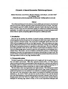
detail view
detail view
suspended capacitive measurement electrode
microsensor interface system
RF inductor/ loop antenna detail view Figure 1. Wireless Microsensor Interface Die. The Interface Die provides sensor measurement, sensor interface, control, and RF communication functions in a single integrated component. The prototype Interface Die, fabricated in commercial 2.0µ CMOS, is integrated with high performance sensor elements by flip chip bonding. These micrographs display the low parasitic capacitance, suspended measurement electrodes, and suspended inductor / loop antenna. The CMOS die was processed after fabrication by a mask-less etch in XeF2 The first integrated wireless microsensors have been implemented with the CMOS Integrated MicroSensors (CIMS) method. CIMS provides devices ranging from inertial to infrared,2 and acoustic sensors in the same process (Figures
1 and 2). CIMS combines commercial CMOS (post-processed after foundry-fabrication by XeF2 micromachining)3 with high performance bulk micromachined sensor and actuator structures (Figure 2) by flip chip bonding. The CIMS process employs an Interface Die (Figure 1) that supports a sensor element (Figure 2). The CMOS interface die is fabricated by commercial foundries and may be postprocessed after fabrication. The interface die may support measurement, control, and communication systems. The CIMS process offers several advances over previous techniques. First, by separating the CMOS and bulk micromachining processes, conventional low cost CMOS technology may be directly applied. This offers system development flexibility to update the circuit technology rapidly to exploit the most optimum processes that become available. In addition, the separation of CMOS and sensor element fabrication permits the introduction of novel materials, for example pyroelectric systems,2 without disturbing critical CMOS processing. As an example, a CIMS accelerometer structure is shown in Figure 2. accelerometer chip micrograph bulk micromachined sensor die
suspended capacitive low parasitic measurement electrode
CMOS Interface Die
ference sources. In addition, wireless microsensor nodes must recover low power transmissions with electrically small loop antennae. Wireless microsensor system design must exploit, therefore, the low duty cycle, low data rate and short transmission range requirements for sensor networks. In addition, spread spectrum signalling with low power frequency hopped implementations provides interference rejection capability. The requirements for wireless microsensors include low average operating power, low peak current (due to compact storage cell limitations), and compact geometry. Compact (2.5 cm diameter, 7mm thickness) Li-based storage cells may provide an average current of 30µA for three years: an adequate lifetime for a broad range of applications. However, cell capacity is rapidly degraded by current values in excess of 10 mA. This defines, therefore a peak current requirement for compact systems. RF system design for wireless microsensors is based on CMOS RF components integrated directly with sensing and control systems. The requirements of extreme low power operation motivates the development of new methods for obtaining low power and high performance RF communication in a multiuser environment. RF system design exploits the characteristics of short range (30 m) and low data rates (less than 10kbps) of typical LWIM applications. The LWIM network requires spread spectrum signalling to provide simultaneous transmission of low bit rate data by many nodes in a single cell. Spectrum spreading by frequency hopping requires drastically lower power than spreading by direct sequence methods. Multipath fading and interference expected for low data rate LWIM systems are sufficiently suppressed by slow hopping at a small fraction of the data rate (many data bits transmitted between hops). RF system power is determined, therefore, by the properties of receiver and transmitter systems operating at a single frequency within the 902-928 MHz ISM band.
III. Low Power Wireless Microsensors: Low Power RF Transceiver
LWIM low power transceiver design has focused on the primary components that determine both power and performance. First, transmitter operation focuses on efficiency in output power amplifiers, operating at 1 - 10mW RF power, and low duty cycle operation. Receiver design, in contrast, is more challenging with the requirements of low noise and high selectivity operation. Also, for some protocols, the wireless sensor receiver must operate at high duty cycle to enable each sensor node to capture randomly arriving signals characteristic of the sensing environment. This paper, therefore, focuses on low power receiver design for wireless sensors with attention to the critical requirements for low phase noise voltage-controlled oscillator (VCO) systems.
The low power wireless sensor network is expected to operate in an environment of densely distributed nodes and inter-
Low power oscillator systems are limited both by the requirements for oscillator loop gain and phase noise. First,
Figure 2. CIMS Accelerometer. The CIMS accelerometer employs capacitive sensing with a suspended measurement electrode. A micromachined cavity drastically reduces substrate parasitics that limit conventional devices. Membrane perforation provide control of squeeze film damping without requirements to perforate the proof mass.
it is noted that fundamental oscillators relying on inductive feedback elements (for example, Colpitts, Pierce, Hartley, and Clapp-Gouriet circuits) display a familiar constraint on minimum feedback loop gain. Now, loop gain is proportional to the quality-factor, Q, of the inductive, resonant feedback network and transconductance. Specifically, the condition for oscillation sets a constraint on the maximum value of the ratio of inductor resistive loss to transistor transconductance.[4] Alternatively, the product of Q and transconductance must be greater than a minimum value. Thus, for a fixed transistor geometry, with transconductance scaling with drain current, ID, the condition for oscillation forces a scaling between inductor Q and transconductance, (1)
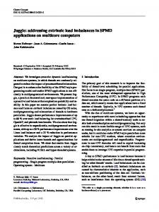
power Colpitts oscillator implemented in 0.8µ HPCMOS using an off-chip wire loop inductor. (This 1cm2 area loop also may function as a transceiver antenna.) The Colpitts oscillator, shown in Figure 3, was supplied with an on-chip buffer amplifier for coupling to 50-ohm measurement systems. Selection of the source resistance in this circuit set drain current. A varactor tuning diode was implemented with a source-substrate junction capacitor shown in Figure 4b. Oscillation at 860 MHz was obtained at a drain current of 20 µA and supply bias of 3V. Tuning over a range of 4MHz with 3V control voltage swing was obtained.
Vdd
a)
1 g m ∝ I D ∝ ---Q
Low power oscillator operation, therefore, requires high-Q inductor systems. Second, receiver selectivity is determined by the stability of each local oscillator required for frequency translation (down conversion) of RF signals. Oscillator phase noise power also scales with Q. Oscillator phase noise power (for frequency, f, near the center carrier frequency, fc) scales with “1/f” or “flicker” noise power.[5] Thus, for an MOS transistor of area WL, flicker noise coefficient, Kflicker, oscillator phase noise power, Sφ, is
(2)
775/0.8
b)
K flicker S φ ∝ ----------------------------------------3 2 Q ( f – f ) ( WL ) c
Equation (1) demonstrates that required drain current for oscillator operation scales inversely with Q2. Similarly, Equation (2) demonstrates that to obtain a fixed phase noise level, transistor area requirements scale inversely with Q2. Low power oscillator operation and performance is, therefore, highly sensitive to and is enhanced by increasing inductor Q. In addition, transistor area requirements scale favorably with increasing Q. The reduction of receiver operating power, without reduction in performance, requires new methods for high Q inductor integration. Inductors implemented with conventional CMOS technology metallization systems provide Q-values in the range of 3-5 for frequencies near 1GHz.[6,7,8] These Q-values are limited by both series resistance loss and loss in supporting substrates. However, compact wire and thick-film inductors display Q-values of 20 -100. The low power wireless sensor systems may, therefore, rely on high-Q inductors packaged with the CMOS transceiver die by the flip-chip methods described above. Several insulating substrate methods provide low-loss dielectric support of thick film metal inductors. A demonstration of this method has been provided by a low
1
1
Cblocking Vcontrol
62/0.8
Figure. 3. The Colpitts VCO implemented in 0.8µ HPCMOS is shown in (a). Frequency control is obtained by a varactor implemented with a source-substrate junction capacitance, shown in (b). Operation of this oscillator was demonstrated at 860MHz with 20µA drain current at 3V supply bias. The high-Q inductor is implemented with an off-chip loop that may also function as a transceiver antenna.
V. Low Power Wireless Microsensor Systems Low power development requires the demonstration of complete systems. Figure 4 shows an LWIM prototype including 1 µA supply current operational amplifiers, a 2 µA supply current voltage to frequency converter, and digital control. Low power and low noise microsensor measurement has been addressed by a system design that optimizes
sensor characteristics and amplifier properties. Low power RF methods have been tested by implementation of a surface-acoustic-wave resonator stabilized, digitally-controlled, regenerative receiver. Micropower CMOS operational amplifier pair
Micropower voltage-frequency converter Micropower CMOS Transceiver
Micropower Integrated Measurement CIMS Integrated Microsensor
Micropower Analog-toDigital Converter
antenna high-Q SAW resonator
The wide range of distributed monitoring and control applications requires microsensors that integrate network interfaces with diverse measurement capability. A low power integrated wireless microsensor technology has been developed using new processes, circuits, and communication systems. MEMS microsensor structures incorporate high performance, bulk micromachined transducers with conventional CMOS microelectronics. Low power sensor interface, digital control, and RF communication systems have been demonstrated. The requirements for low power, high performance RF receiver systems is addressed with the introduction of high-Q inductor systems.
Acknowledgement This work was supported by the Defense Advanced Research Projects Agency (DARPA).
References
Micropower receiver system amplifier/oscillator/ mixer/demodulator
VI. Summary
sampling/ gain control
data out synchronization
Micropower 320MHz CMOS receiver oscillator
Figure 3. Wireless Integrated Sensor System. Measurement, data conversion, and communication systems have been demonstrated in commercial 2µ CMOS. A micropower operational amplifier (supply current 1µA) is combined with micropower voltage-frequency data converters (supply current 2µA). The transceiver is based on a low power CMOS, SAW stabilized and digitally-sampled regenerative architecture (peak supply current 30µA).
[1] A. Burstein and W. J. Kaiser, “Mixed Analog-Digital highly sensitive sensor interface circuit for low cost microsensors”, Sensors and Actuators (in press) [2] J. G. Ho, P. R. Nelson, F. Lin, D. T. Chang, W.J. Kaiser, and O. M. Stafsudd, “Sol-gel derived Lead and Calcium Lead titanate pyroelectric detectors on Si MEMS structures”. Proc. SPIE (in press). [3] F. Chang, R. Yeh, P. Chu, E. Hoffman, E. Kruglick, K. Pister, M. Hecht, “Gas-phase silicon micromachining with xenon difluoride”, Proc. SPIE Microelectronic Structures and Microelectromechanical Devices for Optical Processing and Multimedia Applications, 117-128 (Oct. 1995). [4] E. A. Vittoz, “Micropower techniques”, in Design of Analog-Digital VLSI Circuits for Telecommunications and Signal Processing, New Jersey: Prentice-Hall, 1994, pp 53124. [5] D. B, Leeson, “A simple model of feedback oscillator noise spectra”, Proc. IEEE, vol. 54, pp. 329-330 (1966) [6] J. Y. C. Chang, A. A. Abidi, and M. Gaitan, “Large suspended inductors on silicon and their use in a 2µm CMOS RF amplifier,” IEEE Electron Device Lett., vol. 14, pp. 246248, May 1993. [7] N. M. Nguyen and R. G. Meyer, “Si IC-compatible inductors and LC passive filters,” IEEE J. Solid State Circuits, vol. 25, pp. 1028-31, Aug. 1990. [8] K. B. Ashby, I. A. Koullias, W. C. Finley, J. J. Bastiek, and S. Moinian, “High Q inductors for wireless applications in a complimentary Silicon bipolar process,” IEEE Journal of Solid State Circuits, vol. 31, pp. 4-9, 1996.