ISSN:2229-6093 Vikram Singh Takher,Rajesh Mehra,Abhishek Acharya,Raj Kumar, Int. J. Comp. Tech. Appl., Vol 2 (2), 359-364
Low Read Equivalent Stress Fault Detection in CMOS SRAMs Using MARCH Algorithm Vikram Singh Takher*, Rajesh Mehra**, Abhishek Acharya***, Raj Kumar**** *Lecturer, Department of Electronics Engineering, Govt. Polytechnic College, Bikaner, Rajasthan **Assistant Professor, Department of Electronics & Communication Engineering National Institute of Technical Teachers’ Training & Research, Sector-26, Chandigarh, India ***Assistant Professor, Department of Electronics Engineering, ECB, Bikaner, Rajasthan **** Assistant Professor, Department of Computer Engineering, ECB, Bikaner, Rajasthan *
[email protected], **
[email protected], ***
[email protected], ****
[email protected]
Abstract This paper outlines the reduction of Read Equivalent Stress (RES) during test of SRAM memories and demonstrates that the modified pre-charge activity reduces RES because of the predictable addressing sequence. We exploit this observation in order to show minimization of power dissipation during test by eliminating the unnecessary power consumption associated with RES .Read or write operations on a cell involve a stress on the other cells of the same word line is called Read Equivalent Stress. Read Equivalent Stress has the same effect than a read operation. We have calculated 99.8% reduction in RES with the modified pre-charge activity during test for different MARCH algorithms.
Keywords -SRAM, Low Power, Test March, Precharge, RES, SoC, dRDF, Functional Mode, Test Mode, Resistive open defect, Addressing sequence.
1. Introduction Power dissipation during testing of complex Systems-on-Chip (SoC) has been acknowledged as a large portion of power dissipation. The power dissipation during test mode can be several times larger than in normal functional mode [1,2]. In International Technology Road map for semiconductors (ITRS‟03) indicated that over 90% of SoC silicon area in 2008 will be employed by memories. Minimizing test power in embedded memories of complex Systems-on-Chip is important since they are becoming the main contributor to the overall SoC silicon area.
When a large number of memories are tested simultaneously, the total power dissipation in the tests can exceed power constraints there by generating excessive heat. Further, it causes potential damage in the devices, yield loss and influences the reliability issues. A direct solution to the power problem is to reduce the number of memories tested in parallel so that the power constraint is valued. However, such solutions impose more test time. Much research has been conducted on power constrained test scheduling. The goal of such scheduling is to maximize the parallelism of memory and other IP core testing without exceeding power limits. The effectiveness of these solutions is limited by the power dissipation of each and every memory and other IP cores during test [3, 4, 5]. In order to reduce memory power dissipation during test, proposals for low power memory BIST have been reported [6, 7]. These proposals all use a gray code address generator instead of binary code in order to minimize signal activities in memory address decoders. Except for very small memories, however, power dissipation in decoders is often a negligibly small portion of total memory power. In comparison, power dissipation on the memory data path constitutes significant proportion of the total memory power [8, 9].The faults appear as open defects in VDSM technologies. The study indicates the elaboration of the dynamic Read Destructive Faults (dRDFs). According to this work Read equivalent stress (RES) has the similar effect as the read operation. Further, the well known March C- has been modified. This has been done by changing the addressing order for producing a number of RES. More number of RES increases the power dissipation during test [10].
359
ISSN:2229-6093 Vikram Singh Takher,Rajesh Mehra,Abhishek Acharya,Raj Kumar, Int. J. Comp. Tech. Appl., Vol 2 (2), 359-364
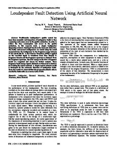
Full functional pre-charge activities are not necessary during test and minimize power dissipation during test by eliminating the unnecessary power consumption associated with the pre-charge activity. This is achieved through a modified pre-charge control circuitry, exploiting the first degree of freedom of March tests. In this work we have analyzed the reduction in RES during testing of different faults in SRAM with different MARCH algorithms for a proposed pre-charge activation model by Dillio Luigi in [11]. 2. March Test Solutions Among the various types Resistive-Open Defects in Core-Cells of test algorithm, March tests allow to reach a good effectiveness with a small complexity. The March test proposed for dRDF detection is generated on the basis of the following requirements[10]: a. The March elements have to be performed on the memory array with addressing order word line after word line. This is necessary to maximize the number of consecutive RESs, because the RESs are produced only by operating on the core cells of the same row. For example, let us consider the SRAM architecture. The read and write operations of the March elements have to be operated first on all the 512 core-cells of the first word line, then on the 512 core-cells of the second word line, and so on. b. The elements of the March test have to include w0 operations necessary for sensitization and r0 necessary for observation. c. Additional elements with w1 and r1 are needed to detect similar faults generated by resistive-open defects placed symmetrically with respect to defect Df4, i.e., in the pull-up of the second inverter composing the core-cell (see Figure 1).
Defects
Figure 1: Resistive-open defects injected into the memory core cell
d. All the elements, in particular the sensitization ones, need to be performed in ⇑ and ⇓ addressing order. In order to justify the last requirement, let us consider the SRAM architecture. If the faulty core-cell is Ci, 0, the first core-cell of the ith row, a March element like ⇑w0 operates a w0 operation on this corecell and is immediately followed by w0 operations performed on the following 511 core-cells of the same row. These w0 operations imply 511 RESs on the faulty core-cell. If the faulty core-cell is the second one of the row, Ci, 1, the same March element ⇓w0 involves 510 RESs on the faulty core-cell. In case the defective core-cell is the last of its row, the element ⇑ w0 does not involve any RES on the defective coreRESmax
RESmin
Figure 2: Distribution of RESs on a core-cell row with the modified March C
cell after the w0 operation. The introduction of a⇓element allows the sensitization phase to be also performed with the opposite addressing order of access on the row. In this condition, the core-cells that endure the maximum number of RESs are those placed in the extremes of the row, while those placed in the middle of the row undergo the smallest number of RESs, i.e., 512/2 = 256 of RESs. In general, if nb_cell is the number of core-cells of each row and nb_op the number of operations (read/write) of the March element (e.g., ⇑w0→nb_op = 1; ⇑r1w0→nb_op = 2), the maximum number of RESs that a core-cell endures is RESmax= (nb_cell − 1) · nb_op and the minimum one is RESmin =(nb_cell · nb_op) / 2 graphically illustrated in Fig. 2, where the name of core-cells is darker when they endure a higher number of RESs. There are various March tests, which already embed most of the requirements described above and that can be modified with the objective to detect dRDFs. For this purpose, the well-known March C- is considered .This is a 10 N linear test, which is effective to detect stuck-at, transition, and 2-coupling { ⇕ (w0) ⇑ (r0, w1) ⇑(r1, w0) ⇓(r0, w1) ⇓(r1, w0) ⇕ (r0)} Figure 3: March C- structure
360
ISSN:2229-6093 Vikram Singh Takher,Rajesh Mehra,Abhishek Acharya,Raj Kumar, Int. J. Comp. Tech. Appl., Vol 2 (2), 359-364
faults and that normally covers 0% of dRDFs .March C- has the structure shown in Figure 3. The first five elements (M0–M4) could be effective for dRDF sensitization because they contain the w0 or w1 operation. In these elements, the read operations, useful for the observation phase, also contribute to the sensitization phase. Both ⇑ and ⇓ addressing orders are operated allowing a good sensitization for all the core-cells. The modification, which makes March C- able to detect dRDFs, consists in the use of the particular address sequence word line after word line. Due to the first of the six degrees of freedom (DOF) of March tests), this modification does not change the capability of March C- to detect the former targeted faults. The efficiency of the modified March C- can be evaluated considering a given SRAM architecture. Let us assume that the defective core-cell is Ci, 0, the first one of row i. Element M2 operates a w0 on Ci, 0, and just after the couple of (r1,w0) operations on the following 511 core-cells of the same row i, resulting in 2·511 = 1022 RESs on the defective core-cell. The same happens if the defective core-cell is Ci, 511, the last one of row i, and the element M4, which is M2 with inversed addressing order, is operated: on core-cell Ci, 511, a w0 operation is acted followed by 1022 RESs. Core-cells Ci, 0 and Ci, 511 endure the maximum number of RESs because they are placed in the extremes of their row. The core-cells placed in the middle of the row are the less stressed with2· (512/2) = 512 RESs. Note that elements M1, as its homologue M3, allows the test of similar faults due to resistive-open defects symmetrically placed with respect to Df4. This modified version of March Cpresents many advantages such as its linear complexity and the reuse of an already existing test algorithm. 3. SRAM Test Mode The addressing order to access the cells and the columns during the memory test mode is predictably known. Therefore, the power dissipation due to precharge and RES could be significantly reduced by precharging the necessary columns. The addressing sequence has been selected as “word line after word line” for the analysis of the SRAM test mode. If the SRAM is organized as an array of n rows x m columns, then read or write operations of each March element need to be operated first on all m cells of the first word line, then on the subsequent m cells of the second word line, and so on. During particular addressing sequence, “word line after word line” when one March element is operated on a certain cell of the array, the subsequent cell to be selected, is placed in the column that immediately
follows [11]. Thus, the pre-charge action is required in two columns of the memory array for a bit oriented SRAM. The first column is needed for each of the subsequent operation of the current March element due to the restoration of the bit line. The second column is needed as the next cell to be selected is placed there. In the SRAM test mode, the selected column, precharge is OFF during the first half of the cycle and is ON during the second half of the cycle as shown in the Figure 4. In the next column to be selected the precharge is turned ON during the entire clock cycle. In the remaining columns the pre-charge circuit can be turned OFF, because the cells of these columns are not involved in the operation 0
1/2 cycle
Pre-Charge OFF-Operation
1ck cycle
Pre-Charge ON- BL restoration
for selected column
Pre-Charge ON- RES
Pre-Charge ON -BL restoration
for unselected column
Figure 4: Pre-charge action for selected and an unselected column
4. Modified Pre-charge Control Logic Functional mode and test mode are modes of operation in SRAM. A functional mode in which the memory acts normally and a low power test mode in which the addressing sequence is fixed to „word line after word line‟ and the pre-charge activity is restricted to two columns for each clock cycle (in bit oriented SRAM) the selected column and the following one(Figure 5). During the final operation on the last cell of each row, the memory returns to functional mode for only one clock cycle to restore the voltage level of all the bit line at VDD. This is necessary in order to prepare the operations in the next row. A practical implementation of proposed SRAM test model consisting in [11] a modification of the precharge control circuitry. The modified pre-charge control logic for model shown in Figure 5 contains an additional element for each column (Figure 6). This element consists of one multiplexer (two transmission gates and one inverter) and one NAND gate. The additional cost of the added logic is ten transistors. The signal LPtest allows write operation. The selection between the functional mode and low power
361
ISSN:2229-6093 Vikram Singh Takher,Rajesh Mehra,Abhishek Acharya,Raj Kumar, Int. J. Comp. Tech. Appl., Vol 2 (2), 359-364
transmission gate-1 will on and functional mode is selected. The modified pre-charge logic has little or no effect on the memory performance during normal operation. The switching between the functional mode and the low power test mode is achieved by a multiplexer implemented by two transmission gates (Figure 6). When the functional mode is selected, one of the transmissions gates (on the right of the precharge control element, Figure 6) allows signal Pr to j
Figure 5: Pre-charge activation model in test mode test mode. The signal Pr is the original pre-charge j
signal, while NPrj is the modified pre-charge signal and CSj is the complementary of the column selection signal. The multiplexer performs the mode selection, while the NAND gate forces the functional mode for the column when it is selected for a read / When LPtest is ON (LPtest = 1), the signal CSj of a selected column j drives the pre-charge of the next column j+1. Note that the pre-charge is active with the input signal NPrj at „0‟. The CS signal of the last column is not connected to the first column pre-charge control, because it is not necessary.
Core cell
Word Line
drive the pre-charge circuit. We have chosen to use transmission gates (two transistors), instead of a single pass transistor, in order to ensure the minimum delay in the transitions (0→1 and 1→0) of the Pr signal j
during the normal functional mode, as well as the CS
j-1
signal during low power test mode.
Figure 7 : Modified Pre-charge control logic circuit Transmission gate2 is on Transmission gate1 is off
Figure 6: Modified Pre-charge control logic circuit Figure 8: Response of Modified Pre-charge control logic circuit
5. Results & Discussions When LPtest=1 transmission gate-2 will ON and test mode is selected means of Pr drives the pre j
charge of selected cell column and the signal CSj of a selected column j drives the pre-charge of the next column j+1 and all other columns remains OFF (Figure 7).This will reduce RES from 511 to 1(for a 512*512 memory block) when a MARCH element operation in progress on selected cell. For LPtest=0
Transmission gate1 is on Transmission gate2 is off
Figure 9: Response of Modified Pre-charge control logic circuit
362
ISSN:2229-6093 Vikram Singh Takher,Rajesh Mehra,Abhishek Acharya,Raj Kumar, Int. J. Comp. Tech. Appl., Vol 2 (2), 359-364
6. Conclusion
References
Modified pre-charge control logic reduces the number of ON pre-charge circuits during the test mode of SRAM.Table1 shows a comparison between reduction in RES during different march algorithms for full precharge activity and modified pre-charge activity. A modified addressing sequence detects new faults and modified pre charge activity reduces 99.8% RES it results in reduction in power. Different MARCH Algorithms uses different numbers of read or write operations for detecting faults in SRAMs. Reduction in RES is largest in MARCH SR 41n because it uses 41 operations.
[1] Semiconductor Industry Association (SIA), “International Technology Road map for semiconductors (ITRS)”, http://www.siaonline.org/home.cfm,2003.
Table 1: Reduction in RES with modified pre-charge activity
512*512 SRAM RES(Full pre-charge activity)[10] RES(Modifie d pre-charge activity)[12] Reduction in RES % Reduction in RES MARCH SR14n
MARCH SS22n
2.9470228*109 5.4921789*109
5755904
10726912
2.9412669*109
5.481452*109
99.8
99.8
MARCH G 23n MARCH RAW 23n
1.8753741*109 3.0809784*109 3662840
6017536
1.8717113*109 3.0749609*109 99.8
MARCH SR 41n
99.8
3.0809784*109 6017536 3.0749609*109 99.8
Acknowledgement The authors would like to thank Dr. S. Chatterji, Professor and Head, Electronics & Communication Engineering Department, NITTTR, Chandigarh for constant encouragement and guidance during this research work.
[2] W. Yuejian and A. Ivanov, “Low Power soc Memory BIST” Proceedings of the 21st IEEE International Symposium on Defect and Fault-tolerance in VLSI systems, pp. 197-205, 2006. [3] B.Wang, j. Yang , W. Yuejian and A. Ivanov, “A Retension-Aware Test Power Model for Embedded SRAMs”,Proceeding of the ASP- DAC, Vol. 2, pp. 11801183, 2005. [4] R.M Chou, K. Saluja and V.D. Agrawal, “Scheduling Test for VLSI systems under power Constarints” ,IEEE Transaction on VLSI ,pp 175-184, 1997. [5] V.Iyengar and K. Chakrabarthy, “ Systems- on a Chip Test scheduling with Precedence, Relationships, Preemption and power constraints”, IEEE Transaction on CAD, vol.21 ,pp. 1088-1094,2002. [6] H. Cheung and S.K. Gupta, “A BIST methodology for Comprehensive Testing of RAM with Reduced heat dissipation”, Proceedings of the IEEE international test conference on test and design validity, pp.386-395, 1996. [7] B.H Fang and N. Nicolici, “Power-Constrained Embedded Memory BIST Proceeding Architecture”, of the 18th IEEE International Symposium on defect and fault tolerance in VLSI Systems , pp.451-458, 2003. [8] K.Kanda, H.Sadaaki and T.Sakurai, “90% write-power saving SRAM using sense-Amplyfying Memory Cell,” IEEE. J. Solid-state circuits, vol. 39, pp.927-933, 2006. [9] R. Saleh, G. Lim, T. Kadowaki and K. Uchiyama “Trends in low power digital system on-chip designs”, Proceedings of the 3rd International symposium on Quality Electronic Design (ISQED)”, pp. 373-378 , 2002. [10] L. Dilillo, P. Girard, S. Pravossoudovitch and A. Virazel, “Efficient March Test Procedure for Dynamic Read destructive Fault Detection in SRAM memories”, Journal of electronic testing: theory and applications, vol. 21, pp. 551561, 2005. [11] L. Dillo , P. Rosinger , B. M. Al-Hashimi, P. Girard “Reducing Power Dissipation in SRAM during Test”, Journal of low power electronics, volume 2,Number 2,pp. 271-280,August 2006. [12] L. Dillo, P. Rosinger, B. M. Al-Hashimi, P. Girard, “Minimizing Test Power in SRAM through Reduction of Pre-charge Activity ”, Proceeding of Design Automation and test in Europe, Vol. 1, pp. 1-6, 2006.
363
ISSN:2229-6093 Vikram Singh Takher,Rajesh Mehra,Abhishek Acharya,Raj Kumar, Int. J. Comp. Tech. Appl., Vol 2 (2), 359-364
Authors:
Vikram Singh Takher: Mr. Vikram Singh Takher is currently Lecturer (senior scale) at Govt. Polytechnic College, Bikaner, Rajasthan, India. He is pursuing his M.E. from NITTTR, Chandigarh, India. He has completed his B.E. from MNIT, Jaipur, Rajasthan, India. Mr. Takher has 14 years of academic experience. He has authored 07 research papers to various international and national conferences. Mr. Takher’s interest areas are VLSI Design, Embedded System Design & Advanced Digital Signal Processing. Mr. Takher has been awarded by “top ten” award of the institute.
awarded by various organizations for excellence in teaching learning process.
Raj Kumar Choudhary: Mr Raj Kumar Choudhary is Assistant professor at Engineering College Bikaner(An autonomous institute of govt of rajasthan),bikaner, Rajasthan. He has completed his B.E. from Engineering College Kota, Rajasthan and M.Tech. from Rajasthan Technical University, Kota , Rajasthan. Mr. Choudhary has 6 years of academics experience. Mr. Choudhary’s interest area is VLSI Design and Computer Archiecture and Processor Design.
Rajesh Mehra: Mr. Rajesh Mehra is currently Assistant Professor at National Institute of Technical Teachers’ Training & Research, Chandigarh, India. He is pursuing his PhD from Panjab University, Chandigarh, India. He has completed his M.E. from NITTTR, Chandigarh, India and B.Tech. from NIT, Jalandhar, India. Mr. Mehra has 15 years of academic experience. He has authored more than 40 research papers in national, international conferences and reputed journals. Mr. Mehra’s interest areas are VLSI Design, Embedded System Design, Advanced Digital Signal Processing, Wireless & Mobile Communication and Digital System Design. Mr. Mehra is life member of ISTE.
Abhishek Acharya: Mr. Abhishek Acharya is currently working as Assistant Professor in the Department of Electronics & Communication at Govt. Engineering College Bikaner. He received his B.E. from University of Rajasthan, Jaipur and he has been a M.E Scholar of NITTTR Chandigarh. He has around 8 years of teaching experience at UG/PG level. He has authored around 15research papers to various international and national conferences. His areas of interest are VLSI Design and its application in signal and image processing systems. Mr. Acharya has been
364