In this thesis we discuss the use of machine learning techniques in the de- velopment of ..... Stereo cameras allow the robot to simulate human binocular vision by using ... trolled by remote control and their level of autonomy is very low. ... 2 CMOS cameras) for text-to-speech synthesis, sound localization, and facial and.
UNIVERSITY OF CASTILLA-LA MANCHA Computing Systems Department
Machine Learning Techniques for Mobile Robot Behaviour Generation Jes´ us Mart´ınez G´ omez
UNIVERSITY OF CASTILLA-LA MANCHA Computing Systems Department
PhD. Program: Doctorado en Tecnolog´ıas Inform´aticas Avanzadas PhD. Thesis Dissertation: Machine Learning Techniques for Mobile Robot Behaviour Generation Author: Jes´ us Mart´ınez G´ omez Advisors: Jos´ e Antonio G´ amez and Ismael Garc´ıa Varea
A mi familia
Acknowledgements This thesis has been partially supported by Spanish Junta de Comunidades de Castilla-La Mancha (JCCM) under PBI05-022, PCI080048-8577 and PBI08-0210-7127 projects; Spanish Ministerio de Educaci´on y Ciencia (MEC) under TIN2004-06204-C03-03, TIN200767418-C03-01 and TIN2010-20900-C04-03 projects; and FEDER funds.
Agradecimientos Esta tesis ha sido parcialmente financiada por la Junta de Comunidades de Castilla-La Mancha (JCCM) bajo los proyectos PBI05022, PCI08-0048-8577 y PBI08-0210-7127; el Ministerio de Educaci´on y Ciencia (MEC) bajo los proyectos TIN2004-06204-C03-03, TIN200767418-C03-01 y TIN2010-20900-C04-03; as´ı como los fondos de desarrollo europeos FEDER.
Abstract The primary goal of this dissertation is to use machine learning and pattern recognition techniques to generate robot behaviour. This thesis presents different contributions in the fields of image processing for robots and self-localization. Robot localization is a key challenge in making truly autonomous robots. In order to localize itself, a robot has access to two sources of information: odometry and measurements. Odometry works by integrating incremental information relative to the motion of the robot over time. Measurements or observations provide information about the location of the robot. Measurements come from the sensors the robot is fitted with and the most common sensors are visual cameras. Therefore, images are the most common measurements and information about the environment can be provided through image processing techniques. In this thesis we discuss the use of machine learning techniques in the development of image processing and localization algorithms. Regarding image processing, we propose genetic algorithms for real-time object detection as well as several classifiers to estimate the quality of the images. The localization problem is tackled in this thesis using two approaches: topological localization and visual place classification. Topological localization assumes that an environment map is provided by an external source and our proposals explore the use of the quality of the images for integrating odometry and observations. Visual place classification is the problem of classifying images depending on semantic areas or rooms. The proposals in this thesis for solving visual place classification are based on the use of clustering techniques and support vector machines. The image processing for these proposals consists of using invariant features and image descriptors.
v
vi
Resumen En esta tesis se aborda el uso de t´ecnicas de aprendizaje autom´atico y reconocimiento de patrones para la generaci´on autom´atica de comportamientos para robots m´oviles. Las principales contribuciones aqu´ı presentadas est´an relacionadas con el procesamiento de im´agenes para robots m´oviles y el problema de la autolocalizaci´on. La autolocalizaci´on de robots es un problema clave en el desarrollo de robots completamente aut´onomos. Para poder localizarse, un robot accede a dos distintas fuentes de informaci´on: odometr´ıa y observaciones. La odometr´ıa proporciona al robot, de forma incremental, informaci´on relativa a los movimientos que este realiza en el entorno. Las observaciones aportan informaci´on relativa a la localizaci´on del robot y son adquiridas a trav´es de los distintos sensores con lo que el robot est´a equipado. Dado que las c´amaras de visi´on son el principal sensor del robot, la forma de obtener informaci´on de localizaci´on desde las observaciones es utilizar t´ecnicas de procesamiento de im´agenes. En esta tesis se proporciona un amplio estudio sobre el uso de aprendizaje autom´atico para desarrollar algoritmos de procesamiento de im´agenes y localizaci´on. En relaci´on con el procesamiento de im´agenes, proponemos el uso de algoritmos gen´eticos para la detecci´on de objetos en tiempo real, as´ı como diversos clasificadores que estimen la calidad de las im´agenes capturadas. El problema de localizaci´on se aborda utilizando dos puntos de vista: localizaci´on topol´ogica y clasificaci´on de espacios visuales. La localizaci´on topol´ogica asume que se puede obtener con anterioridad un mapa del entorno y nuestras propuestas plantean el uso de la calidad de las im´agenes para integrar de forma efectiva odometr´ıa y observaciones. La clasificaci´on de espacios visuales consiste en clasificar im´agenes adquiridas por un robot utilizando para ello ´areas sem´anticas. Las propuestas planteadas para su resoluci´on se basan en el uso de t´ecnicas de clustering y m´aquinas de vector de soporte. El procesamiento visual se basa en el uso de caracter´ısticas invariantes y descriptores visuales.
vii
viii
Preface Introduction Robot localization is a key problem in making fully autonomous mobile robots. This problem consists of answering the question “Where am I?” from a robot’s point of view. In order to localize itself, a robot senses the environment to retrieve as information as much possible from it. Given this information, the robot uses an internal representation of the environment to determine its location. The goal of localization is to determine the robot’s location as accurately as possible. There are two main sources of information for performing localization: odometry and sensorial information. Odometry gives the robot feedback about its motion actions. The sensorial information allows the robot to obtain the situation of the environment around the robot. Both sources of information are iteratively combined using mathematical estimators such as the Kalman Filter (KF) or the Monte Carlo Localization method (MCL). Odometry is an uncertain source of information that relies on the physical characteristics of the robot. The error in the odometer readings depends on the type of robot: biped, four-legged or wheeled. The algorithms for retrieving odometry information are too specific and difficult to generalize. On the other hand, sensorial information depends on the sensors the robot is fitted with. Most of the robots are equipped with generic visual cameras and such sensors can be considered the most common. The processing of the images acquired with robotic visual cameras is a challenging task that presents several restrictions. All the processing has to be performed in real-time with limited computational resources. Due to these characteristics, most of the current image processing algorithms are based on ad-hoc solutions using simple techniques such as scan lines or blob extraction. These algorithms are difficult to generalize for generic object detection and they are not robust to lighting variations and noisy data.
ix
This thesis proposes the development of generic and high quality image processing algorithms for robots (with a special focus on localization). We propose the use of well-known machine learning techniques and meta-heuristics to achieve such a goal. The image processing algorithms generated in this way are easy to understand and also to replicate. The Kalman Filter and Monte Carlo are techniques that have these characteristics. Although the localization challenge can be considered solved for controlled environments under optimal conditions, uncontrolled environments still represent a challenging scenario. Within uncontrolled environments (such as domestic homes) the robot must have a semantic representation of the space instead of using absolute positions. The challenge of classifying images depending on semantic areas is called “visual place classification” or sometimes “place recognition”. This challenge is receiving increasing attention, and since 2009 the prestigious Cross Language Evaluation Forum (CLEF) hosts a task dedicated to this problem. In this dissertation we study ways of solving the visual place classification task by using automatic learning techniques. The process consists of a training phase where sequences of well-annotated images are available. This phase generates a classifier that allows the robot to classify images in the scope of semantic areas. We also propose some steps for the development of an unsupervised learning algorithm for visual place classification.
General Objectives The scientific goals of this thesis are divided into two groups, namely:
Image processing algorithms The main objective is the generation of high-quality image processing algorithms through the use of meta-heuristics. We focus on image processing algorithms applied to localization. The goal of these algorithms is to retrieve information from the environment and use it to determine the location of the robot.
Localization of robots We shall differentiate in this thesis between two types of localization problems: topological localization and visual place classification. The main objectives are
x
the improvement of well-known topological localization methods and the proposal of novel approaches for solving the visual place classification problem. Another important objective of this thesis is to form the basis for a future unsupervised learning algorithm for localization within uncontrolled environments. This basis is expected to be generated by using the experience acquired in the RobotVision task that addresses the visual place classification problem.
Structure of the dissertation This dissertation is structured in four parts. Part I is composed of Chapters 1 to 3. Chapter 1 presents a general introduction to autonomous robots. Chapter 2 is fully devoted to a biographical revision of computer vision for robotics and localization techniques. Chapter 3 presents the list of scientific and technological goals of this thesis. The second part, Part II, is composed of Chapter 4 and Chapter 5. These two Chapters present the methodological contributions of this thesis. The proposals related to image processing for robots are presented in Chapter 4 while the contributions to robotic self-localization are described in Chapter 5. Part III contains two chapters, Chapter 6 and Chapter 7, which are devoted to the empirical results of the evaluation of all the techniques presented in Chapters 4 and 5. Finally, Part IV focuses on the conclusions and future work. This part is composed of Chapter 8, in which the main conclusions of the dissertation are discussed, as well as a list of future directions for further developments.
xi
xii
Contents I
Introduction
1
1 Autonomous Robots 1.1 Introduction to robotics . . . . 1.1.1 Sensors . . . . . . . . . . 1.1.2 Actuators . . . . . . . . 1.1.3 Central Processing Unit 1.1.4 Robots and Databases .
. . . . .
. . . . .
. . . . .
. . . . .
. . . . .
. . . . .
. . . . .
. . . . .
. . . . .
. . . . .
. . . . .
3 3 4 6 7 8
2 State Of the Art 2.1 Computer Vision . . . . . . . . . . . . . . . . . 2.1.1 Image Segmentation . . . . . . . . . . . 2.1.2 Scan Lines . . . . . . . . . . . . . . . . . 2.1.3 Invariant Features Extraction: SIFT . . 2.2 Topological localization . . . . . . . . . . . . . . 2.2.1 Proposals for the RoboCup competition 2.2.2 Other Proposals . . . . . . . . . . . . . . 2.3 Visual Place Classification . . . . . . . . . . . . 2.3.1 Proposals for the RobotVision challenge 2.4 Summary . . . . . . . . . . . . . . . . . . . . .
. . . . . . . . . .
. . . . . . . . . .
. . . . . . . . . .
. . . . . . . . . .
. . . . . . . . . .
. . . . . . . . . .
. . . . . . . . . .
. . . . . . . . . .
. . . . . . . . . .
. . . . . . . . . .
11 11 13 15 16 20 22 30 31 33 37
. . . . .
. . . . .
. . . . .
. . . . .
. . . . .
. . . . .
. . . . .
. . . . .
3 Scientific Goals
41
II
43
Methodological contributions
4 Image Processing for Robots 4.1 Detection of localization elements in the RoboCup environment . 4.1.1 Genetic Algorithms for Real-Time Object Detection . . . . 4.1.2 Using cellular GAs for real-time RoboCup goals detection . 4.2 Image Quality Evaluation . . . . . . . . . . . . . . . . . . . . . . 4.2.1 Image Quality Evaluation for colour segmentation methods
i
45 45 46 54 57 58
CONTENTS
4.3 4.4 4.5 4.6
Lighting conditions dependence . . . . . . . . . . . 4.3.1 Robust Vision System with Automatic Filter SIFT-based improvements . . . . . . . . . . . . . . 4.4.1 Discarding outliers by using RANSAC . . . Detection of doors for indoor environments . . . . . Summary . . . . . . . . . . . . . . . . . . . . . . .
. . . . . . . Calibration . . . . . . . . . . . . . . . . . . . . . . . . . . . .
. . . . . .
62 64 69 71 75 77
5 Self-Localization Methods 79 5.1 Topological localization . . . . . . . . . . . . . . . . . . . . . . . . 79 5.1.1 Improving the Markov localization method by using Image Quality Evaluation . . . . . . . . . . . . . . . . . . . . . . 81 5.1.2 Integration of detections performed by using Genetic Algorithms . . . . . . . . . . . . . . . . . . . . . . . . . . . . . 84 5.1.3 Stability estimation and controlled population restarts for the Monte Carlo localization method . . . . . . . . . . . . 88 5.2 Visual Place Classification . . . . . . . . . . . . . . . . . . . . . . 94 5.2.1 Combining Image Invariant Features and Clustering Techniques for Visual Place Classification . . . . . . . . . . . . 94 5.2.2 A Multi-Cue Discriminative Approach to Semantic Place Classification . . . . . . . . . . . . . . . . . . . . . . . . . 98 5.2.3 Towards semi-supervised learning for visual place classification . . . . . . . . . . . . . . . . . . . . . . . . . . . . . 103 5.3 Summary . . . . . . . . . . . . . . . . . . . . . . . . . . . . . . . 110
III
Experimental Results
113
6 Experimental results for RoboCup environments 6.1 Overview of the RoboCup environment . . . . . . . . . . . . . . . 6.2 Detection of RoboCup elements . . . . . . . . . . . . . . . . . . . 6.2.1 Genetic Algorithms for goals and ball recognition . . . . . 6.2.2 Cellular Genetic Algorithms for Goal Detection . . . . . . 6.3 Robot localization within the soccer field . . . . . . . . . . . . . . 6.3.1 Improving the Markov localization method by using image quality evaluation . . . . . . . . . . . . . . . . . . . . . . . 6.3.2 Robust Vision System with Automatic Filter Calibration . 6.4 Summary . . . . . . . . . . . . . . . . . . . . . . . . . . . . . . .
115 116 117 118 124 127 128 133 137
7 Experimental results for the RobotVision challenge 139 7.1 RobotVision@ImageCLEF 2009 . . . . . . . . . . . . . . . . . . . 139 7.2 RobotVision@ICPR 2010 . . . . . . . . . . . . . . . . . . . . . . . 143
ii
CONTENTS
7.3 7.4
7.5
IV
RobotVision@ImageCLEF 2010 . . . . . . . . . . . . . . . . . . . 144 Semi-Supervised Learning for Visual Place Classification . . . . . 147 7.4.1 Experiment 1.- Memory-Controlled OI-SVM . . . . . . . . 148 7.4.2 Experiment 2.- Confidence estimation for detecting challenging frames . . . . . . . . . . . . . . . . . . . . . . . . . 151 7.4.3 Experiment 3.- Retraining the classifier with the MC-OI-SVM153 Summary . . . . . . . . . . . . . . . . . . . . . . . . . . . . . . . 157
Conclusions
159
8 Conclusions 161 8.1 Conclusions . . . . . . . . . . . . . . . . . . . . . . . . . . . . . . 161 8.2 Contributions to the Literature . . . . . . . . . . . . . . . . . . . 162 A RobotVision Task A.1 Data Set . . . . . . . . . . . A.2 Performance Evaluation . . A.3 Results . . . . . . . . . . . . A.3.1 Participant proposals
. . . .
. . . .
References
. . . .
. . . .
. . . .
. . . .
. . . .
. . . .
. . . .
. . . .
. . . .
. . . .
. . . .
. . . .
. . . .
. . . .
. . . .
. . . .
. . . .
. . . .
. . . .
167 169 173 174 175 191
iii
CONTENTS
iv
List of Figures 1.1 1.2 1.3 1.4 1.5 2.1 2.2
Omnidirectional camera and an example of the images captured with this camera. . . . . . . . . . . . . . . . . . . . . . . . . . . . Legged BigDog traversing difficult terrain. . . . . . . . . . . . . . Robots equipped with emotional (left) and military actuators (right). Examples of bio-inspired robots: ant, hexapod, salamander and turtle. . . . . . . . . . . . . . . . . . . . . . . . . . . . . . . . . . Aldebaran Nao (left) and Sony AIBO(right) robotics platforms. .
2.10 2.11 2.12 2.13
RoboCup soccer field from the 2006 four-legged league. . . . . . . Example of colour segmentation where the original image was acquired using an AIBO robot within a RoboCup environment. . . . Horizon detection by using scan lines. . . . . . . . . . . . . . . . . Several types of door that can be found within indoor office environments. . . . . . . . . . . . . . . . . . . . . . . . . . . . . . . . Example of SIFT point extraction. Left: Original Image. Right: Features Extracted. . . . . . . . . . . . . . . . . . . . . . . . . . . Situations where odometry is not useful to estimate a robot’s location. . . . . . . . . . . . . . . . . . . . . . . . . . . . . . . . . . Execution of the Kalman Filter. . . . . . . . . . . . . . . . . . . . Discrete (left) and continuous (right) representation of the robot’s location. . . . . . . . . . . . . . . . . . . . . . . . . . . . . . . . . Fuzzy set representation of an angle measurement θ (left) and trapezoid intersection (right). . . . . . . . . . . . . . . . . . . . . 3D-point map generated with current SLAM techniques. . . . . . Process for visual word generation from a set of images. . . . . . . Data mapping into a feature space by using a kernel function. . . RoboCup soccer field evolution. . . . . . . . . . . . . . . . . . . .
4.1 4.2 4.3
Yellow goal partially captured and colour filtering. . . . . . . . . . Graphical representation of individual genes. . . . . . . . . . . . . Two captures showing the same goal but varying the θ parameter.
2.3 2.4 2.5 2.6 2.7 2.8 2.9
v
5 6 7 8 8 12 13 16 17 19 21 23 25 29 32 35 36 38 46 50 51
LIST OF FIGURES
4.4 4.5 4.6 4.7 4.8
4.9 4.10
4.11 4.12 4.13 4.14 4.15 4.16 4.17 4.18
4.19
4.20
4.21
5.1
Pixel distribution obtained after an orange filtering (left) and evaluation of 12 individuals to detect the ball (right). . . . . . . . . . Cellular (a) and Panmictic (b) structures. . . . . . . . . . . . . . Individual fitness evolution for a panmictic (left) and a cellular (right) GA. A bubble diameter represents the fitness of the individual. Example of an image acquired with the camera of the NAO used in the experiments. . . . . . . . . . . . . . . . . . . . . . . . . . . Colour segmentation for a RoboCup image. Original image (left), yellow region obtained with thresholding (middle) and a regionbased method (right). . . . . . . . . . . . . . . . . . . . . . . . . . Average x and y of the pixels that belong to the yellow region after a colour segmentation. . . . . . . . . . . . . . . . . . . . . . . . . Images classified as low quality (top left) and high quality (top right). Yellow pixels obtained with segmentation for both images (bottom). . . . . . . . . . . . . . . . . . . . . . . . . . . . . . . . Difference between YUV and RGB colour representations. . . . . Snapshot of the 2009 RoboCup competition and colour values of two pixels belonging to the field carpet. . . . . . . . . . . . . . . . Vision system that uses scan lines for object recognition in the four-legged RoboCup competition. . . . . . . . . . . . . . . . . . . Dynamic filter establishment. . . . . . . . . . . . . . . . . . . . . Dynamic filter establishment scheme. . . . . . . . . . . . . . . . . Images acquired from the same viewpoint with fast (top row) and medium (bottom row) shutter speed. . . . . . . . . . . . . . . . . SIFT matching between two images where an invalid matching is represented with a yellow dotted line. . . . . . . . . . . . . . . . . First model of matching considered: lines with similar gradient. Initial matching (blue lines in top image) and discarding outliers (red lines in bottom image). . . . . . . . . . . . . . . . . . . . . . Second model of matching considered: lines that intersect at the same point. Initial matching (blue lines in left image) and discarding outliers (red lines in right image). . . . . . . . . . . . . . . . . Complete process for extracting blobs. Left: original image. Middle: Vertical line detection. Right: Homogeneous colour distributions between two vertical lines (BLOB extraction). . . . . . . . . Door detection for four consecutive frames. Top images are the original frames using P for preliminary candidates and D for definitive ones. Bottom images show the blobs extracted and time correspondence between them. . . . . . . . . . . . . . . . . . . . . . Problems with the Nao motion model in 2008. . . . . . . . . . . .
vi
51 55 56 56
59 60
61 63 63 65 66 68 68 70
73
74
76
76 81
LIST OF FIGURES
5.2 5.3 5.4 5.5 5.6 5.7 5.8 5.9 5.10
5.11 5.12 5.13 5.14 5.15 5.16 5.17 5.18 5.19 5.20 6.1 6.2 6.3
IQE Markov process: that is, the Markov method using the image quality evaluation. . . . . . . . . . . . . . . . . . . . . . . . . . . Localization information extracted with detection of two goals. . . Image acquisition with wrong colour segmentation and the occupation grid generated. . . . . . . . . . . . . . . . . . . . . . . . . Occupation grid taking into account the quality of the detections. Estimation of the location of a robot from the genes of the best individual. . . . . . . . . . . . . . . . . . . . . . . . . . . . . . . . Locations obtained with the detections of a genetic algorithm. . . Low-quality RobotVision task images. . . . . . . . . . . . . . . . . Problems encountered with particle re-initialization. Error for position estimation. . . . . . . . . . . . . . . . . . . . . . . . . . . . Localization process for three consecutive frames. Left: the process is stable and the most reliable robot pose is stored. Middle: the process fails due to low quality of an acquired frame. Right: the population is initialized over a restricted area. . . . . . . . . . . . Difference computed between two frames. . . . . . . . . . . . . . . An example of sequence pre-processing where redundant frames are discarded and the best candidates are selected. . . . . . . . . . Test frame classification using a similarity ranking of 6 training frames. . . . . . . . . . . . . . . . . . . . . . . . . . . . . . . . . . Overall view of the training and classification process. . . . . . . . Example of the oversampling process. Two new training frames are generated using an original training image as template. . . . . Decision margins obtained for an ideal frame (left) and two types of challenging frames (middle and right). . . . . . . . . . . . . . . Complete classification process where non-challenging frames are used to retrain the classifier. . . . . . . . . . . . . . . . . . . . . . Number of stored training samples for different M axT Ss values. . Conditional probabilities (M ) obtained for an ideal frame and two types of challenging frames. . . . . . . . . . . . . . . . . . . . . . Percentage of correctly-classified, misclassified, and not-classified frames using (right), and not using (left), confidence estimation. .
84 85 86 86 88 89 90 91
93 96 96 97 99 101 102 104 106 107 110
Size and shape difference for the yellow goal in the 2008 - 2010 competitions (left) and the 2007 - 2008 competition (right). . . . . 117 Mean error evolution for ten executions of a cellular GA without restarts. . . . . . . . . . . . . . . . . . . . . . . . . . . . . . . . . 126 Four-legged RoboCup field (2007 edition) used for the experimentation. . . . . . . . . . . . . . . . . . . . . . . . . . . . . . . . . . 128
vii
LIST OF FIGURES
6.4 6.5 6.6 6.7 6.8
Robot tour for Experiment 1 (left), Experiment 2 (middle) and Experiment 3 (right). . . . . . . . . . . . . . . . . . . . . . . . . . Error in the distance estimation when facing low quality images. . Error in distance estimation when facing a kidnapping situation. . RoboCup goal colours: expected (left) and obtained (middle and right). . . . . . . . . . . . . . . . . . . . . . . . . . . . . . . . . . Tours for the first (left) and second (right) experiment. . . . . . .
129 131 132 133 135
7.1
Results for the RobotVision@ImageCLEF 2009. Percentage of test frames that are correctly classified, not classified and missclasified for both tasks. . . . . . . . . . . . . . . . . . . . . . . . . . . . . . 142 7.2 RobotVision@ICPR 2010. Distribution of test frames that are correctly classified, not classified and misclassified for both tasks. . . 145 7.3 RobotVision@ImageCLEF 2010. Distribution of test frames that are correctly classified, not classified and misclassified for both tasks.146 7.4 9 combinations of training and testing sequences selected from the COLD-Freiburg database. . . . . . . . . . . . . . . . . . . . . . . 148 7.5 Classification error rate (processing the whole test sequence) obtained incrementally for the 9 combinations of training and testing sequences from the COLD-Freiburg database, obtained for different M axT Ss values. . . . . . . . . . . . . . . . . . . . . . . . . . 149 7.6 Average number of support vectors stored for Experiment 1. . . . 150 7.7 Experiment 2. Percentage of correctly-classified, wrongly-classified and not-classified frames using (right), and not using (left), the confidence estimation. . . . . . . . . . . . . . . . . . . . . . . . . 152 7.8 Relative accumulated error obtained for the 9 combinations of training and testing sequences from the COLD-Freiburg database, obtained with adding and original MC-OISVM. Dark areas represent new rooms not present in the training data. . . . . . . . . . . 154 7.9 Relative accumulated error obtained for the CLEF database, obtained with adding and original MC-OISVM. Dark areas represent new rooms not imaged previously. . . . . . . . . . . . . . . . . . . 155 7.10 Relative accumulated error for a Cloudy-Night combination. . . . 156 7.11 Relative accumulated error for a Night-Night combination. . . . . 156 7.12 Relative accumulated error for a Sunny-Night combination. . . . . 157 A.1 A.2 A.3 A.4 A.5
Robots used to acquire the images of the CLEF database. . . . . Examples of images from the CLEF 2009 database. . . . . . . . . Examples of images from the CLEF 2010@ICPR database. . . . . Examples of images from the CLEF 2010@ImageCLEF database. System architecture of the GSARRC proposal. . . . . . . . . . . .
viii
168 171 172 172 176
Part I Introduction
1
Chapter 1 Autonomous Robots 1.1
Introduction to robotics
The first use of the word “robot” was made by the acclaimed Czech playwright Karel Capek in January 1921. This word appeared in his play Rossum’s Universal Robots and it comes from the Czech word “Robota” meaning literally hard work. This first definition of the word robot (“artificial people able to perform tasks and think for themselves”) was close to the current idea of androids (synthetic organism designed to look and act like a human) but far from the first commercial robots of the late fifties. The first set of commercial robots (1960-1980) was unable to perform complex tasks and their autonomy level was extremely low. They were designed and constructed just to carry out specific jobs (mainly transporting and manipulation) and in most cases they consisted of a jointed arm with an end actuator. With the fast evolution of technology in the last decades of the twentieth century, it became feasible to tackle new challenges by using robots. These new challenges were not only related to industry but also to social life, increasing the level of demands in terms of design and functionality. New aspects such as a friendly interface, sociability, mobility or autonomy had to be considered. The physical appearance of the robot became one of the most important keystones for the design. The actuators and effectors were selected depending on the environment the robot was going to be used in. While the first robots were manufactured to be used within specific and static environments, the new robots had to operate autonomously in dynamic and heterogeneous environments. Homes are one of the most challenging environments, due to their variability and the risks of interacting with people. Domestic robots
3
1. AUTONOMOUS ROBOTS
can harm a human who is interacting with it (especially young children or babies) but the robot also can be damaged by humans. Moravec (2003) (Robotics Institute of the Carnegie Mellon University) describes the future evolution of robotics technology using four generations of robots similar to reptiles, mice, monkeys and finally, humans. Moravec predicts the arrival of these new generations of robots by 2020 (first generation, lizard-like). It is difficult to find a global classification for current robots accepted by most authors in the literature. Most robot classifications are based on the design, the type of motion they use (fixed, legged or wheeled) or the task they are programmed to perform (industrial, service, social, or military robots). This thesis is focused on general-purpose autonomous mobile robots. These characteristics are described below: • General-purpose: Robots that carry out a variety of functions simultaneously. • Autonomous: Desired tasks are performed without continuous human guidance. • Mobile: Capability to move within their environment by using actuators (mainly wheels and legs). Mobile robots are usually fitted with several sensors, a set of actuators and a central processing unit (CPU). Sensors are used to perceive and gather data from the environment. Actuators allow the robot to navigate, manipulate and interact with the environment. The central processing unit gives the robot the ability to make choices by processing the information sensed from the environment and sending orders to the actuators.
1.1.1
Sensors
Visual cameras are the most important sensor for robots. There are different types of visual cameras, but they all obtain a representation of the environment based on colour and luminance information. Visual cameras are cheap, easy to use and well-documented. The type of visual camera that should be selected depends on the problem we are facing. A monocular camera is the simplest model we can find nowadays, but such a type of visual camera can only sense 2-Dimensional
4
1.1 Introduction to robotics
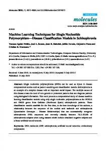
information from a specific direction. Omnidirectional cameras should be considered for navigation and obstacle avoidance and also for solving simultaneous localization and mapping (SLAM) tasks. An omnidirectional camera is usually composed of a lens and a lower and upper mirror. Thanks to the use of these mirrors, the field of vision of the camera is increased to 360 degrees. Figure 1.1 (left) shows an omnidirectional camera used in the RoboCup middle-size league (Brainstormers Tribots team). An example of the images captured with this camera is also shown in Fig. 1.1 (right).
Figure 1.1: Omnidirectional camera and an example of the images captured with this camera.
Stereo cameras allow the robot to simulate human binocular vision by using two separate lenses. These cameras obtain 3-Dimensional information and the pair of images can be used to extract depth information from the environment. Alternatively, autonomous robots can be equipped with other types of cameras (mainly thermo-graphic and infrared). The use of this type of cameras is usually related to specific purposes (search and rescue operations, motion caption or night vision). Other devices that are commonly fitted on an autonomous robot are touch and distance sensors (mainly laser and ultrasonic sensors). Human robot interaction can require physical contact between both agents and touch sensors become necessary. Distance sensors appear as the key sensor for SLAM problems.
5
1. AUTONOMOUS ROBOTS
1.1.2
Actuators
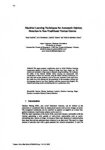
Ulike the homogeneity of robot sensors (mainly cameras and distance sensors), there are a large number of alternatives when it comes to actuators. The type of actuator selected will depend on the movement and interaction requirements of the environment. According to the actuators used for motion, mobile robots can be classified as legged robots (including humanoids) or wheeled robots. The most important progress in motion devices over the last few years has been the development of the legged BigDog robot (Raibert et al., 2008). This robot is capable of traversing difficult terrain at 6.4 km per hour carrying 150 kg. Figure 1.2 shows this robot, created by Boston Dynamics, NASA and Harvard University.
Figure 1.2: Legged BigDog traversing difficult terrain. The robot actuators (not related to motion) are needed to manipulate and interact with the environment. Humanoid robots are usually fitted (at least) with grasping hands and a set of specific effectors (eyes, eyelashes, eyebrows) that are useful to express emotions. An example of a humanoid social robot equipped with emotional sensors and actuators is “Maggie” (Fig. 1.3 left), developed by the Spanish University Carlos III. Robots designed for military applications are equipped with manipulators for disarming explosive devices and also rifles, machine guns or grenade launchers. These robots (equipped with complex and dangerous actuators) are usually controlled by remote control and their level of autonomy is very low. The most well-known military robot is the Foster-Miller TALON (Fig. 1.3 right), from the
6
1.1 Introduction to robotics
Figure 1.3: Robots equipped with emotional (left) and military actuators (right). US army. This robot has performed a large number of explosive ordnance disposal missions in the conflicts in Irak and Afghanistan.
1.1.3
Central Processing Unit
The central processing unit is responsible for making the correct decision after sensing the environment. This decision will be translated into orders sent to the actuators and updates of the internal state. Processing time is a critical point for robotic systems because all tasks must be carried out in real-time. The algorithms should be robust to noise and low quality input data and the robot must be able to make decisions under uncertainty. Fuzzy logic (Fukuda & Kubota, 1999), decision rules or trees (Kitano, 1998) and Bayesian approaches (Lebeltel et al., 2004) are the main options that can be found to develop the “intelligence” of a robot. As the author of this thesis is a member of the Intelligent Systems and Data Mining research group (SIMD from its initials in Spanish)1 an important objective of this thesis is to take advantage of the research group’s background to solve specific open robotic problems. The interests of the SIMD group are: machine learning, data mining, decision making under uncertainty (Bayesian networks and fuzzy logic), metaheuristics, and evolutive computation (genetic algorithms and ant colony systems), among others. The two open problems selected to be solved are robot self-localization and image processing for robots. The motivation for this selection will be described in Chapters 4 and 5. Both problems are of course key points for any 1
http://www.dsi.uclm.es/simd/
7
1. AUTONOMOUS ROBOTS
autonomous mobile robot. In the same way that some current robots imitate biological locomotion models (these robots are called bio-inspired robots and some examples are shown in Fig. 1.4), several biological behaviours can be imitated to develop algorithms (bio-inspired algorithms) (Brooks, 1992; Dain, 1998).
Figure 1.4: Examples of bio-inspired robots: ant, hexapod, salamander and turtle.
1.1.4
Robots and Databases
All the developments in this thesis have been carried out using two robotic platforms (Sony AIBO and Aldebaran Nao) and image databases proposed for robot localization (KTH-IDOL2 (Luo et al., 2006) and COLD: COsy Localization Database (Pronobis & Caputo, 2009)).
Figure 1.5: Aldebaran Nao (left) and Sony AIBO(right) robotics platforms.
8
1.1 Introduction to robotics
AIBO (Fig. 1.5 right) is a robotic dog from Sony created as an artificial pet. This bio-inspired four-legged robot has been commonly used as a platform for research, because it integrates a vision system, a set of actuators and sensors, a wireless connection and a computer. It was the official robotic platform of the RoboCup four-legged robot soccer league from 1999 to 2008. Aldebaran Nao (Fig. 1.5 left) is the humanoid robot that replaced AIBO as the robot used in the RoboCup. This robot (RoboCup edition) has 21 degrees of freedom and it features a powerful multimedia system (4 microphones, 2 speakers, 2 CMOS cameras) for text-to-speech synthesis, sound localization, and facial and shape recognition, amongst other capabilities.
9
1. AUTONOMOUS ROBOTS
10
Chapter 2 State Of the Art This chapter introduces the theoretical background of this thesis and reviews the state of the art in two important open robotic problems: computer vision and robot localization.
2.1
Computer Vision
Computer vision is the technology that tries to replicate the human vision process on computers, obtaining internal representations from the environment. This process can be carried out by following different approaches: working on colour features (Hsu et al., 2002), detecting edges (Ziou & Tabbone, 1998), visual words (Yang et al., 2007) or using stereo information (Hirschm¨ uller (2005)). This section reviews the literature related to computer vision techniques with a special focus on mobile robotics. The image processing algorithms under study acquire information from the environment and use it to perform decision making or other robotic purposes. The processing time and memory requirements of these techniques should be as small as possible and they have to work properly even when facing noisy data or under uncertainty. The information extracted from the environment depends on the specific purpose of the robot. For autonomous mobile robots, this information is usually related to the localization and navigation process: the robot should detect and avoid obstacles (Lenser & Veloso, 2003) and estimate the distance to localization elements to obtain its own pose (Enderle et al., 2001). Social robots have to decide how to interact with other agents (humans or other robots) and select which agent requires most attention (Breazeal et al., 2001). These decisions are taken using the information extracted from the envi-
11
2. STATE OF THE ART
ronment, normally with visual cameras. The algorithms for visual attention have to process video sequences (a set of images with time correspondence), detecting gestures (Wu & Huang, 1999) and also the pose of the human who is interacting with it (Shakhnarovich et al., 2003). The RoboCup soccer championship is a perfect scenario where real-time visual processing algorithms have been tested and proved (Lima & Cust´odio, 2005). All the elements within a RoboCup soccer field (shown in Fig. 2.1) are colour-coded (green carpet, orange ball, blue and yellow goals, white lines) and the first approaches were mainly based on the use of colour information (Brusey & Padgham, 2000).
Figure 2.1: RoboCup soccer field from the 2006 four-legged league. There are several leagues within the RoboCup soccer domain: standard platform, small size, middle size, humanoid and simulation. This thesis is focused on the Standard Platform League1 (formerly four-legged league), which is the only one where all the teams use identical physical robots. This league has used two platforms since its start in 1999: Sony AIBO and Aldebaran NAO. Sony AIBO is a robot that is fitted with a hardware colour detection engine. Thanks to the use of this engine, up to 8 different colour filterings can be performed efficiently by hardware. This filtering was useful to detect the key elements in the first editions 1
http://www.tzi.de/spl/bin/view/Website/WebHome
12
2.1 Computer Vision
of the competition and it was used as the basis for more complex developments (such as, for example, edge detection in Murch & Chalup (2004)). Colour-based approaches are not very useful when the robot has to operate within uncontrolled environments such as indoor offices. The landmarks used to localize the robot in these environments are elements that are difficult to detect and they are not usually colour-coded. These elements are very different from those used in the RoboCup scope (beacons, goals or field lines) and colour information is not a discriminative feature to detect them. Windows, doors, lights, desktops or computers are commonly used as landmarks. Ranganathan et al. (2002) describe a navigation and localization method that uses all the rectangular planar objects (doors, windows, posters, . . . ) located on the walls as natural landmarks.
2.1.1
Image Segmentation
Image segmentation (sometimes called blob extraction) can be considered as one of the simplest techniques for extracting information from visual data. This method categorizes all the pixels in an image as belonging to one of several previously-defined regions (according to different criteria). The membership of each pixel to a region (blob) is defined by using similarity values based on colour, intensity or texture information. The result of this processing will be a set of n blobs or equivalent regions. Figure 2.2 shows the result of applying colour segmentation with four colours (white, green, blue and yellow) to an image taken with the AIBO’s camera.
Figure 2.2: Example of colour segmentation where the original image was acquired using an AIBO robot within a RoboCup environment.
13
2. STATE OF THE ART
A formal definition (see Equation (2.1)) of image segmentation is given in (Pal & Pal, 1993): If F is the set of pixels and P () is a homogeneity predicate defined in groups of connected pixels, then segmentation is a partition of the set F into a set of regions (S1 , S2 , . . . , Sn ) such that n [
Si = F
with
Si
\
Sj = ∅, i 6= j
(2.1)
i=i
The uniformity predicate P (Si )=true for all regions and P (Si when Si and Sj are neighbours.
S
Sj )=false,
Wasik & Saffiotti (2002) classify the methods for colour segmentation into three approaches: thresholding techniques, region-based methods and boundarybased methods. In spite of this classification, these approaches are usually combined to achieve better segmentation, obtaining a fourth type of segmentation technique: hybrid methods. These four approaches are summarized below: • Thresholding techniques: All pixels with a similar colour belong to the same region. Threshold techniques rely on this assumption and only the colour thresholds have to be defined. Each colour will define a blob. This was a common technique for early RoboCup teams (such as the proposal presented in (Bruce et al., 2002)) because of the fact that the AIBO robot implements an inexpensive colour-filtering hardware. Thresholding techniques need careful tuning of the thresholds and the main drawback is that they are very sensitive to variations in the lighting conditions. • Region-based methods: These methods (Haralick & Shapiro, 1985) assume that neighbouring pixels in the same region should have similar colour values. The most common implementation of region-based methods is seeded region growing, proposed in (Adams & Bischof, 1994). The idea behind region growing algorithms is to select a set of initial regions that are iteratively grown. Each region grows by comparing all unallocated neighbouring pixels with that region. At each time-step, the unallocated pixel with the smallest difference is assigned to the respective region. This process continues until all pixels belong to a region. The selection of the initial seeds should be performed carefully but some proposals perform it automatically (Grinias & Tziritas, 2001; Shih & Cheng, 2005). • Boundary-based methods: Boundary-based methods (e.g. Ma & Manjunath (1997)) rely on the assumption that the colour and intensity of the
14
2.1 Computer Vision
pixels should present big variations between different regions. These methods use well-known edge detectors such as that of Sobel or Canny (Canny, 1987) to identify the borders of these regions. The main drawback of these methods is that the obtained colour (or intensity) edges can be discontinuous or even over-detected. • Hybrid techniques: Some proposals integrate the results of two (or more) segmentation methods. The most common hybrid method (used in (Pavlidis & Liow, 1990)) combines region growing (region-based) and edge detection (boundary-based). These methods take advantage of the regions provided by edge detection to initialize the seeds for seeded region growing. This was the technique used in (Fan et al., 2001), where an interesting application of the segmentation algorithm to automatic face detection is discussed. The set of regions (or blobs) obtained with an image segmentation method and their characteristics are normally used as the input for more complex object recognizers. The characteristics that are stored by region are the number of pixels and some statistics such as the average x and y position of all the pixels that belong to the region. Thanks to the segmentation technique the amount of data to work with can be drastically reduced, and therefore non-interesting pixels can be discarded.
2.1.2
Scan Lines
Scan lines is a computer vision technique that examines an image using parallel lines that check colour or luminance variations. This simple technique has been commonly used in combination with image segmentation within the RoboCup domain, as proposed in Lenser & Veloso (2003) to develop a visual sonar. The grid of scan lines is used to reduce the number of pixels processed, and therefore the visual processing time is speeded up. This grid of scan lines is defined by its orientation, direction and the gap between two consecutive lines. An example of scan lines extracted from (J¨ ungel et al., 2004), and used to detect the horizon, is shown in Fig. 2.3. Scan-lines-based methods have been proven to be an efficient solution for solving the problem of landmark (goals and beacons) detection in the first years of the RoboCup four-legged competition (R¨ofer et al., 2003). A localization beacon (such as that shown in Fig. 2.3) is always observed as a rectangle made up of a set of colour coded squares. A beacon can be detected by using a single scan line that covers all the appropriate colours. The distance to a goal or beacon can be
15
2. STATE OF THE ART
Figure 2.3: Horizon detection by using scan lines. estimated by using the size of the section of the scan line that detects the element (small sections will represent distant elements). The main drawback of using scan lines for object detection is their poor performance when facing real-world situations. Images captured within a robotic soccer match can present occlusions or partial captures of the element we want to detect. Scan lines present problems with this type of images as they may fail at object recognition and distance estimation. Because of this important drawback, other techniques should be considered for performing real-world object recognition.
2.1.3
Invariant Features Extraction: SIFT
Colour-based methods proved to work properly for object recognition within the RoboCup soccer environment. This happened because the specifications (colour and shape) of all the field elements (goals, beacons, lines and players) were already known and no variations for these specifications were expected. The information extracted from object recognition (mainly distance and orientation to localization elements) could be used to estimate the robot’s real pose and also to obtain the position of the ball and the other robotic soccer players. Thanks to this information, the robot can plan secure paths and make the correct decisions it was designed for. Within uncontrolled environments (such as indoor offices), the localization process becomes more challenging due to the lack of artificial landmarks. Localization beacons are not present and natural landmarks have to be selected as localization elements. Dulimart & Jain (1997) present a localization system that
16
2.1 Computer Vision
used ceiling lights and “door number plates” as natural landmarks. Ceiling lights seemed to be the best alternative (Mart´ın et al., 2006; Wang et al., 2007) for natural landmarks for several reasons: • The high contrast between the light and the ceiling surface makes them easy to detect. • Ceiling lights are visible (and rarely occluded) from most of the points of the environment using overhead cameras pointed to the ceiling. • Almost all indoor environments are fitted with ceiling lights. Unfortunately, not all robots are fitted with an overhead camera and other natural landmarks (such as doors or windows) have to be considered. Natural landmarks are defined in a general way but not all their characteristics (colour and shape) are specifically given. For instance, an office door is composed of a rectangle placed in a wall and a mechanism used to open and close it. The dimension and colour of doors that are expected to be found within an office environment can present big variations, as is shown in Fig. 2.4.
Figure 2.4: Several types of door that can be found within indoor office environments. All these reasons hinder the generation of localization algorithms for generic indoor environments, especially when these algorithms have to be based solely on visual information. The pure global localization challenge (determining the robot’s absolute location from sensor data) for generic indoor environments was assumed to be solved by using accurate distance sensors (as will be seen in Section 2.3). A new (and easier) type of localization was then proposed for using only vision cameras: determining the semantic area where the robot is situated from visual data.
17
2. STATE OF THE ART
This new challenge of classifying images depending on the room (or area) they are taken in is known as “visual place classification” or “place recognition”. The localization process with place classification approaches is based on context interpretation instead of pure geometric models. Global topological localization and place classification could be used together in order to improve the accuracy of both methods. Pronobis et al. (2006) present “place classification” as a useful method for loop closing or recovery from the kidnapped robot problem. Ulrich & Nourbakhsh (2000) propose an approach for “place recognition” that uses training sequences of well-annotated images. They assumed that the localization algorithm could be automatically obtained from a sequence of representative locations of the environment. The training sequence must contain images labelled with the room they were acquired from. Ulrich and Nourbakhsh’s approach consisted of determining the training image that was most similar in appearance to the input image. In spite of using the adjacency relationship to avoid comparing the current image with the whole training sequence, the number of matches was too high. In order to fulfil real-time requirements, Ulrich and Nourbakhsh use a compact representation of the image based on colour histograms (Swain & Ballard, 1991). Torralba & Sinha (2001) present another interesting algorithm for recognizing indoor scenes. Instead of classifying the images by comparing them with the whole training sequence, they generated a classifier. This classifier was based on → → the conditional probabilistic function p(Ci | vc ) where vc are the features extracted from the image that is going to be classified and Ci are the labels for all the semantic areas. Torralba and Sinha select structural features (Oliva & Torralba, 2001) extracted by using band-passed filters. After generating the classifier, the complete training sequence can be discarded. The main problem of using the features presented in (Ulrich & Nourbakhsh, 2000) and (Torralba & Sinha, 2001) is their dependency on the camera viewpoint: features extracted from images displaying the same scene will be different when the viewpoint of the camera has been modified. Ideal features should be invariant to image scaling, rotation, and also to illumination changes. In 1999 Lowe presented an algorithm for extracting local features. This method was named SIFT (Scale-Invariant Feature Transform) and since its release, it has been widely used. This method has been applied for localization, tracking, object recognition and 3D modelling with successful results. The specification of Lowe’s method and several examples of SIFT recognitions
18
2.1 Computer Vision
are presented in (Lowe, 2004). Keypoints are detected by using a cascade filtering approach. The complete process consists of the following steps: 1. Search over all scales and image locations. It is implemented efficiently by using a difference-of-Gaussian function to identify potential interest points that are invariant to scale and orientation. 2. At each candidate location, a model is fitted to determine location and scale. Keypoints are selected based on measures of their stability. 3. Orientations are assigned to each keypoint location based on local image gradient directions. 4. The local image gradients are measured at the selected scale in the region around each keypoint. These gradients are transformed into a representation that allows for significant levels of local shape distortion and change in illumination. Figure 2.5 shows an example of the SIFT process performed over a 698x588 pixel image, where 5342 invariant points were extracted.
Figure 2.5: Example of SIFT point extraction. Left: Original Image. Right: Features Extracted. The number of SIFT points extracted depends on the image used as input, and therefore big variations can arise when using different images. Features extracted are invariant to image scale and rotation, and they are also robust to noise and changes in viewpoint.
19
2. STATE OF THE ART
The main application of SIFT is object recognition (Bicego et al., 2006; Dork´o & Schmid, 2003). Object recognition can be easily performed by matching the SIFT points computed in the test image with the SIFT points extracted from a template image (or a set of images) where the object to be recognized is displayed. An important advantage of using invariant features for object recognition is the robustness to partial object occlusion. On the other hand, the algorithm presents a high computational cost, which is an important drawback for real-time systems.
2.2
Topological localization
The generic problem of localization consists in answering the question “Where am I?” (Leonard & Durrant-Whyte, 1991). This means the robot has to estimate its location within the environment. Therefore, the robot should have an internal representation of the environment where it is placed. The most common representation of the environment is a map but other approaches can be adopted. The main advantage of using maps is the opportunity of obtaining the complete robot pose < x, y, θ > in a global coordinate system. Environment maps can be already known (such as in the RoboCup competition) or have to be automatically generated. The process of generating maps while the robot is being localized is known as SLAM and this will be reviewed in Subsection 2.2.2. An environment map can be defined exhaustively (topological maps where all the walls and fixed elements are described) or just using the absolute position of a set of natural/artificial landmarks (RoboCup soccer field). Some environments are not described by any map but by using semantic areas instead, following a space representation similar to humans (Kuipers & Byun, 1991). This alternative description can be adopted when the robot is not fitted with accurate sensors, and therefore no maps can be generated. This representation could also be selected when the environment is expected to undergo big variations (the maps should be updated continuously). This is the environment description given in the RobotVision task at the ImageCLEF challenge (Pronobis & Caputo, 2010), where a set of well-annotated images are provided as a training sequence. In this thesis we shall differentiate between two types of localization problems: topological localization (appropriate for controlled environments) and visual place classification (for uncontrolled environments).We define controlled environments as those that are not expected to undergo big variations. Topological localization for controlled environments is the task of estimating the pose of the robot given
20
2.2 Topological localization
a map of the environment and a history of sensor readings and executed motion actions (odometry). In Section 2.2.1 we will review the most common localization approaches for the RoboCup competition. Indoor environments where components (such as furniture) are expected to be added, replaced or relocated are defined as uncontrolled. The localization process for uncontrolled environments (”‘visual place classification”’) is reduced to a classification problem where the class is related to semantic areas and the input is a sequence of images acquired with a mobile robot. The semantic areas (classes) are usually defined in terms of their visual appearance (e.g. the corridor), the activities we usually perform in them (e.g. the fitness room) and the objects they contain (e.g. the bedroom). There are two main sources of information for the topological localization process: sensorial (history of sensor readings) and odometry (executed motion actions). The first one allows the robot to acquire information from the environment by using visual and distance sensors. Odometry determines changes in the location of the robot thanks to the use of the robot’s last location and the data from the motion sensors. Even when using wheeled robots (where motion accuracy is supposed to be higher), odometry presents several problems concerning accuracy. Odometry estimates the robot’s location relative to a starting location and a movement. The errors from previous time-steps affect the current process and small errors can have a big impact on future pose estimations. Moreover, the uncertainty about the position variation after a movement is higher when the robot interacts with other agents (people or other robots) within a dynamic environment.
Figure 2.6: Situations where odometry is not useful to estimate a robot’s location.
21
2. STATE OF THE ART
Figure 2.6 shows two RoboCup match situations where players close to the ball cannot use odometry to determine their position accurately. The two robotic players are fighting for the ball and sending the order ’move forward’ to their legged joints but the robot’s position is fixed (due to the opponent).
2.2.1
Proposals for the RoboCup competition
Since the beginnings of the RoboCup competition, two mathematical methods have been widely used to create topological localization methods: Kalman Filters and Particle Filters (Monte Carlo localization). Kalman-filter-based methods are appropriate for accurate sensors and low-uncertainty environments. On the other hand, Monte Carlo allows the robot to represent uncertainty about its own location. An interesting comparison of these two (and other) methods within the RoboCup scenario can be found in (Gutmann & Fox, 2002). Mart´ın et al. (2007) summarize the localization methods used in the fourlegged league of the 2005 RoboCup soccer competition. In that edition, 18 out of 21 teams used a localization method based on Monte Carlo (12 teams), Kalman Filters (3 teams) or a combination of both proposals (3 teams). In addition, 2 teams used a localization method based on triangulation (only the visual information for each time-step was considered) and TeamChaos1 used a fuzzy logic Markov method.
Kalman Filters The Kalman Filter (Kalman et al., 1960) is a recursive data processing algorithm that estimates the state of a noisy linear dynamic system. In this thesis, the state to be estimated is the complete pose of a mobile robot. Kalman filtering assumes that the model and the sensors are perturbed by Gaussian noise. Beliefs are propagated over time while new measurements are incorporated. This method works with continuous values and the extended version (Extended Kalman Filters) does not need to assume Gaussian densities. The inherent drawback in Kalman filtering is that only one pose hypothesis can be represented. In order to show how this method works, Fig. 2.7 shows a basic example of Kalman filter execution. The x-axis represents time and blue lines represent the 1
http://www.teamchaos.es/index.php/TeamChaos
22
2.2 Topological localization
measured position (single dimension) of a robot within its environment. It can be observed that measured positions present big variations in short time steps. These measurements differ from the robot’s real position (red line), but thanks to the Kalman Filter, the estimated position (green line) is closer to the true one.
Figure 2.7: Execution of the Kalman Filter. The method consists of a recursive algorithm with a prediction and an update phase (both defined by mathematical equations). The algorithm starts with an initial position X0 that has to be defined previously. Prediction Phase The prediction phase (Equation (2.2)) produces two matrices with the predicted pose (X∗t ) and the predicted covariance (Pt∗ ). Two additional matrices are used within this phase: A represents the variation for the robot location which has a direct correspondence with the odometry, and Q represents the white noise assumed by the method. That is,
X∗t = A × Xt Pt∗ = A × Pt × AT + Q
(2.2)
This phase does not include observation information from the current time
23
2. STATE OF THE ART
step. The estimated location (X∗t ) will be updated (with the information acquired from the sensors) at the update phase. Update Phase This phase updates the value of the robot’s pose and the covariance. Three equations (Equation (2.3)) are used to obtain the new values and to update an internal parameter called optimal Kalman gain (K). Kalman gain selects the importance of the observation (Z) for the a posteriori location of the robot (Xt ). The parameter R represents the white noise assumed by the observation. Pt∗ Pt∗ + R ∗ Xt = Xt + K(Z − X∗t ) Pt = (I − K)Pt∗ K=
(2.3)
The value of Xt will be closer to X∗t when there are small values for K, which denote situations where the algorithm assumes a high level of uncertainty for the sensorial source of information. The value of K will be close to 1.0 if the algorithm trusts the information retrieved from the sensorial data. The Kalman Filter presents optimal behaviour when facing problems with a large number of reliable measurements and a known initial position. The main advantage of this method is the low computational cost and the small memory requirements. On the other hand, several parameters have to be established (Q and R), the initial position has to be already known and uncertainty cannot be represented (just a single robot pose is considered). Due to these drawbacks, the Kalman Filter localization method is not suitable for use within dynamic environments, especially when the robot’s pose can undergo quick variations. Within the RoboCup scenario, kidnappings must be taken into account: a referee can pick up a robot and move it to a different location if the robot performs a forbidden action. Due to the kidnappings (and the impossibility of representing uncertainty) other localization methods are more popular than the Kalman Filter for the RoboCup competition.
Markov Localization Markov localization (Fox et al., 1999) was proposed as a probabilistic approach for solving the problem of robot location estimation. This method uses a probability
24
2.2 Topological localization
distribution over all the possible robot locations in the environment. The probability distribution is updated with odometry and visual information. P (Lt = l) represents the robot’s belief of being situated at position l at time t. A gridbased environment partition provides a discrete approximation of the probability distribution for the whole environment, as shown in Fig. 2.8 (left).
Figure 2.8: Discrete (left) and continuous (right) representation of the robot’s location. The algorithm iteratively obtains the most likely pose using odometry and sensor information. Initial probabilities can be uniformly distributed to represent uncertainty about the robot’s initial pose. Alternatively, initial probabilities can be defined to represent knowledge about the robot’s starting pose. Prediction Phase This phase obtains the most probable pose by using the last pose and the last motion action a. It is necessary to define an odometry model to obtain the pose variation after a movement. This phase obtains a new probability distribution using Equation (2.4), where P (Lt = l00 ) is the probability of being situated at location l00 at time t and p(l0 |l00 , a) represents the probability of being moved from location l00 to l0 with the motion action a.
25
2. STATE OF THE ART
P (Lt+1 = l0 ) =
X
p(l0 |l00 , a) · P (Lt = l00 )
(2.4)
l00
After this phase, the probability distribution for the robot’s location has been estimated. Update Phase The second phase is the update phase, in which the information obtained from all the robot’s sensors has to be integrated. Visual information or infrared sensors are the most common information sources. With this new probability distribution, we have two different sources, and it is necessary to combine the odometry and sensorial information. This combination is performed as follows:.
P (Lt+1 = l) = p(z|l0 ) · P (Lt+1 = l0 )
(2.5)
The new belief P (Lt+1 = l) is obtained using the probability distribution from the first phase P (Lt+1 = l0 ) and p(z|l0 ), which represents the likelihood of sensing the measurement z from the location l0 . The classical Markov method has been used for years in the RoboCup competition (Penedo et al., 2003). It is a simple method that keeps the uncertainty about the robot’s pose. The main drawback is the grid-based discrete representation: an accurate process (big number of small cells) involves a high computational cost.
Monte Carlo Localization Method The Monte Carlo Localization method (MCL) was proposed in (Dellaert et al., 1999) to solve the grid-based representation problem of Markov localization. The key idea of Monte Carlo localization is to represent robot position estimation by a set of n particles or samples. The MCL method spreads a set of particles Sk = {sik ; i = 1...n} over an environment representation (map). Each one of these particles represents a robot pose < x, y, θ >. An iterative process applies a motion model to each one of these particles and performs the update step. The evaluation of each particle is obtained by processing the information sensed from the environment (measurements).
26
2.2 Topological localization
After all the particles have been evaluated (obtaining the importance weights), a sampling step is applied by using the Monte Carlo method (Handschin, 1970). Best candidates tend to be duplicated, and worst particles should disappear from the distribution. After several iterations, the algorithm will converge and all the particles should be placed around the real robot pose. The algorithm is applied as a recursive Bayesian filter, and it determines the position of a robot given a map of its environment and a set of measurements. The MCL-method represents probability density by maintaining a set of samples instead of describing the probability density function itself. The density representation (a set of particles) is updated. Like all the other methods already presented, the MCL-method consists of two phases that are performed iteratively. Before performing the first prediction phase, a new population of particles has to be created. These particles can be randomly spread over the whole environment, representing a uniform density over all allowable positions. Prediction Phase Starting from the set of particles Sk−1 computed in the last iteration, this phase applies the motion model using odometry. Each particle is sampled from the density p(xk |sik−1 , uk−1 ): (i) for each particle sik−1 : draw one sample s0 ik from p(xk |sik−1 , uk−1 ) This phase generates a new set of particles that have not yet incorporated any sensor measurement. Update Phase The information extracted from the environment with the sensors (zk ) is incorporated in the update phase. Each of the particles is weighted by mik = p(zk |s0 ik ), which represents the likelihood of observing the measurement z from the location represented by the particle s0 ik . The new set of particles Sk is obtained by resampling from the weighted set of particles: (ii) for j = 1...N : draw one Sk sample sik from {s0 ik , mik } After the update phase, steps (i) and (ii) are repeated iteratively.
27
2. STATE OF THE ART
In contrast to the Kalman filter, the MCL-method keeps information about different robot locations and thus it can perform a global robot localization. The amount of memory required by the MCL-method is drastically lower than that required by the Markov localization method. The method is easy and fast to implement and several modifications to the original implementation are feasible.
Hybrid Methods Although most of the localization proposals for the RoboCup competition are based on either Kalman Filters, or the Markov or Monte Carlo localization methods, not all the teams use the standard version of these methods. It is very common to find localization methods combining certain features from these methods (Gutmann, 2002). The main objective of these hybrid proposals is to generate a new localization method without the drawbacks of the original method they are based on. The elements of the original algorithm that are going to be combined should be carefully selected. Fuzzy Logic - Markov One of the hybrid proposals within the RoboCup competition is the localization method used by Team Chaos for the four-legged soccer league. Their proposal (Buschka et al., 2000) is a Markov-based method combined with fuzzy logic (Zadeh, 1978). This technique is developed as a localization technique suitable for robots with poor odometry. The robot’s belief about its own position is represented by a probability distribution based on the use of position grids (similar to Markov). The innovation in this technique is that they propose the use of 3D fuzzy position grids that can represent multiple positions where the robot might be situated. Instead of modelling all the orientations in a grid, the method uses a fuzzy trapezoid (Fig. 2.9 left) that represents the uncertainty about the orientation of the robot. A trapezoidal fuzzy set is defined by its (x, y) position and several parameters: θ (most probable robot orientation), ∆ (the width of the core), h (height), b (bias) and α (slope). Trapezoids with small ∆ and b values will be used to represent a grid where we have low uncertainty about robot orientation. The process is defined as for Markov localization (a prediction and an update phase applied iteratively). In this case, all the operations are performed using fuzzy trapezoids. Updating, translating, blurring, and computing the centre of
28
2.2 Topological localization
Fuzzy Trapezoid
Intersection
Figure 2.9: Fuzzy set representation of an angle measurement θ (left) and trapezoid intersection (right). gravity (CoG) of the fuzzy grids presents nice computational properties. These operations are all linear in the number of cells. The update phase is performed using two steps: observation and update. Observation obtains a new distribution of fuzzy sets after landmark detection. Update combines this new distribution with the a priori distribution from the prediction phase. This combination is performed by intersecting the fuzzy trapezoids that correspond to the same (x, y) position. This process is shown in Fig. 2.9 right. This proposal was an effective solution to the problem of localization in the RoboCup scope, but it presented the drawbacks arising from the use of a gridbased representation. For a deeper study of this proposal please refer to (HerreroP´erez et al., 2005). Fuzzy Markov method and Kalman filters Another interesting hybrid technique was proposed in (Mart´ın et al., 2007). This method combines the fuzzy Markovian method presented above with a population of Extended Kalman Filters (EKFs). The basis of this work is the Markovian fuzzy logic algorithm, which provides global localization and recovery abilities (needed for kidnappings or false positives). The information obtained with this first algorithm is used to generate several EKFs that are computationally light and very accurate. An EKFs can be removed from the population if its position presents problems with the information provided with the Markovian algorithm. Each EKF is generated using the Markovian information to establish the EFK initial pose. In view of the results presented in (Mart´ın et al., 2007), the algorithm proved
29
2. STATE OF THE ART
adequate for the RoboCup environment constraints and the functional needs. In this work, the authors compared the accuracy and execution time of their proposal (FMK + EKF), the standard Extended Kalman Filter (EKF) and the Fuzzy Markov (FMK) localization method (Buschka et al. (2000)). FMK + EKF was the algorithm that presented the highest accuracy and robustness when facing the three proposed scenarios (simple movement, kidnapping and a noisy environment). Additionally, the computational time of FMK + EKF was similar to EKF and it required up to ten times less computational resources than FMK.
2.2.2
Other Proposals
Simultaneous Localization and Mapping (SLAM) All the methods presented above assume that it is possible to use an accurate map of the environment. This assumption is true within the scope of RoboCup soccer, where the field is accurately described (width of the lines, dimensions of the goal, colours of the elements and lighting conditions) in the competition rule book 1 . Other robotic platforms (especially general purpose robots) have to discover the environment they are going to navigate. The best way to obtain an accurate representation of the environment is to create geometrically consistent maps that will be used to determine future robot locations. This technique (known as mapping) is performed by sensing the environment from different viewpoints and it involves robot navigation (and therefore localization). Simultaneous localization and mapping is known as SLAM (Thrun, 2008) and it can be considered as a chicken or egg problem. The SLAM problem can be defined as the problem faced by a mobile platform roaming in an unknown environment, and seeking to localize itself and map the environment at the same time. The three classic 2D SLAM paradigms from which most of the others were derived are: 1. Extended Kalman Filters (EKF). 2. Graph-based optimization techniques. 3. Particle filter Methods. EKFs were proposed for solving the SLAM problem in the late eighties and early nineties in (Smith & Cheeseman, 1986) and (Leonard & Durrant-Whyte, 1
http://www.tzi.de/spl/pub/Website/Downloads/Rules2011.pdf
30
2.3 Visual Place Classification
1991). These first EKF implementations for SLAM assumed that several landmarks could be used to localize the robot but no accurate topological maps were generated. This technique is similar to that presented in Section 2.2.1 for localization. The first working solution of using a graph-based optimization technique for solving 2D SLAM was proposed in (Lu & Milios, 1997). The location of the robot and the different landmarks are considered as nodes on a graph. Odometry information is codified as the arcs that link localization nodes. Other arcs represent the relationship between a landmark and the robot’s location after the landmark is sensed and detected. A good example of a more recent SLAM proposal using a graph-based optimization technique is the Graph SLAM algorithm proposed in (Thrun & Montemerlo, 2006). Finally, the third paradigm is based on the use of particle filters. Taking into account that environment maps can be huge (and that particle filters scale exponentially with the dimension of the state space), standard implementations of particle filters are not feasible. FastSLAM was the name of the method proposed in (Montemerlo et al., 2002), where each particle represents a robot’s path and a set of landmark detections (represented by Gaussians). 2D topological maps have been replaced by 3D visual maps thanks to the use of accurate lasers and high quality visual cameras. The 2D SLAM problem is usually considered solved and current research directions are based on the integration of the large amount of data generated by the sensors. An example of a 3D-point map generated by the method presented in (Newman et al., 2006) is shown in Fig. 2.10, where the accuracy level achieved can be seen.
2.3
Visual Place Classification
The localization methods for controlled environments assume that a topological map can be used for future robot localizations. This map can be known beforehand (RoboCup environments) or it may have to be discovered (SLAM), but environment modifications will have a negative impact on the localization process. Uncontrolled environments define places where the position of all the elements can vary, due to the intervention of humans or other robots. These environments can be domestic rooms where windows and doors can be opened or closed, chairs can be placed at different locations and other agents can be present.
31
2. STATE OF THE ART
Figure 2.10: 3D-point map generated with current SLAM techniques. Within these environments, the robot will behave differently depending on the room or area where it is currently situated. Even the motion of the robot can be different if it is placed in the corridor (where it will navigate faster) or within a kitchen (where all the movements have to be performed carefully). The robot should behave more like humans, having a semantic representation of the space instead of just knowing its absolute location. Visual place classification or place recognition are the names used to denote the challenge of classifying images depending on semantic areas. The number of classes (semantic areas) will depend on the robot’s purpose, but each class is usually related to a room category. Additionally, two or more physical rooms can share the same class. The prestigious Cross Language Evaluation Forum (CLEF) hosted in 2009 (Pronobis et al., 2010c) a new task dedicated to the visual place classification problem. Two new editions took place in 2010 (2010@ICPR (Pronobis et al., 2010a) and 2010@CLEF (Pronobis et al., 2010b)) and a large number of researchers presented their proposals for solving this challenge.
32
2.3 Visual Place Classification
2.3.1
Proposals for the RobotVision challenge
Participants in the RobotVision task are asked to classify rooms and semantic areas on the basis of image sequences captured by a camera. This camera is mounted on a mobile robot that moves within an office environment under varying illumination conditions. Proposed systems should be able to answer the question “where are you?” when presented with test sequences containing images acquired in the previously observed part of the environment (using different viewpoints and acquired under different lighting conditions) or in additional rooms that were not imaged in the training stage (these rooms should be labelled with the new room category). There are two subtasks: obligatory and optional. For the first subtask, the classification has to be performed without taking into account the order and the relationship between frames. The second subtask is optional but it is more closely related to robot localization. Within this subtask, the classification algorithms can take advantage of the continuity in the sequence of test frames. The competition starts with the release of annotated training and validation image sequences from a database: COLD-Stockholm (Pronobis & Caputo, 2009) in 2010 and KHL-IDOL2 (Luo et al., 2006) in 2009. These data sets could be used to train different systems and to evaluate their goodness by using the validation data set. The final test image sequence is released later and contains images acquired in the same environment but including additional rooms not imaged previously. In addition, lighting conditions vary from the training to the validation and test sequences. A more detailed description of the task is presented in Appendix A. Most of the participant proposals use techniques based on the similarity between training and test frames. These techniques compute the similarity between the complete training sequence and a test frame. After computing all similarities they label the test frame using the class of the most similar training frames. Similarity is computed using invariant features extracted from the images. Other techniques generate a classifier using the information retrieved from the training sequence or use approaches based on the use of visual words. We present below these two techniques.
33
2. STATE OF THE ART
Visual Place Categorization by using Visual Words The Computer Vision Group (CVG), from the ETH Z¨ urich, was the winner of the obligatory task for the second edition of the RobotVision task (2010@ICPR). This group presented (Fraundorfer et al., 2010) a novel and interesting proposal based on the use of visual words (Fraundorfer et al., 2008). This approach assumes that each semantic category (class) can be defined as a set of elements. A kitchen is defined as a room fitted with elements such as a fridge, a microwave, a cooker and a kitchen sink. It also can be equipped with common elements such as a table and several chairs. This reasoning is similar to that performed by humans: we usually link the elements that we find within a room with its purpose. A room will be considered as a bathroom even if we see just a single image showing a distinctive element such as a bathtub. The CVG represents in (Fraundorfer et al., 2010) each location by a list of visual words. This list of visual words (from each location) forms a document vector that is translated into a histogram. The similarity between two frames is computed by using the histogram once the set of visual words is obtained. A very interesting work is presented in (Yang et al., 2007), where the idea of using visual words for scene classification is fully covered. Figure 2.11 graphically shows the process of generating the visual word vocabulary. An appropriate selection of the vocabulary of visual words is the keystone of this technique. This task is the most challenging and the performance of the classifier will depend on dictionary generation.
Support Vector Machine Classifiers Support Vector Machines (Vapnik, 2000) is a supervised learning method used for classification and regression analysis. The algorithm was proposed by Vladimir Vapnik in 1979 but it is only since 2000 that it has begun to receive serious attention. This method has been proposed to solve several current classification problems, some of them highly related to visual place classification, such as text categorization (Joachims, 1998). A brief description of SVMs is presented below.
34
2.3 Visual Place Classification
Figure 2.11: Process for visual word generation from a set of images.
Assume {xi , yi }li=1 , with xi ∈ Rm and yi ∈ {−1, 1}, is a set of samples and labels drawn from an unknown probability distribution; we want to find a function f (x) such that sign(f (x)) best determines the category of any future sample x. In the most general setting,
f (x) =
l X
αi yi K(x, xi ) + b
(2.6)
i=1
where b ∈ R and K(x1 , x2 ) = Φ(x1 ) · Φ(x2 ), the kernel function, evaluates inner products between images of the samples through a non-linear mapping Φ. The αi are Lagrangian coefficients obtained by solving (the dual Lagrangian form of) the following problem:
35
2. STATE OF THE ART
min w,b
1 ||w||2 2
+C
Pl
p i=1 ξi
(2.7)
subject to yi (w · xi + b) ≥ 1 − ξi ξi ≥ 0 where w defines a separating hyperplane in the feature space, i.e., the space where Φ lives, whereas ξi ∈ R are slack variables, C ∈ R+ is an error penalty coefficient and p is usually 1 or 2. In practice, most of the αi are found to be zero after training; the vectors with an associated αi different from zero are called support vectors. Notice that, from Equation (2.6), the classification time of a new point is proportional to the number of SVs, hence reducing the number of SVs implies reducing the classification time. The kernel function maps data into a feature space where they can be easily separated. There are several types of kernels that can be applied: linear, polynomial, exponential, Gaussian or Laplacian. Figure 2.12 shows an example of a data mapping into a feature space by using a kernel function.
Figure 2.12: Data mapping into a feature space by using a kernel function. In 2009 the Laboratoire des Sciences de l’Information et des Syst`emes (LSIS) presented a proposal (GLOTIN et al., 2009) for the first edition of the RobotVision task that constructs a Support Vector Machine using two different types of features. These features are the new Profile Entropy Features (PEF) and the generic Descriptor of Fourier (Smach et al., 2008). The SVM classifier is generated by using 19 sub-classes created from the 5 original rooms. A total of 19
36
2.4 Summary
different binary SVM classifiers were generated and their outputs were combined to get the final decision. The most important point of using SVMs for visual place classification is the input selection. Features extracted from the images must be carefully chosen. The dimension of the features extracted is not a problem when using SVMs because this technique can handle high-dimensional inputs without memory overflow problems. The input (x) of the SVM algorithm can be generated as a combination of different global or local features. SIFT-based features are the most popular (Pronobis et al., 2008; Tommasi et al., 2009) but other specific features, such as PEF, can also be created. The main drawback of SVM-based methods is the large execution time needed for training the classifier. On the contrary, the classification time is close to 0. These classifiers have proved their goodness in other scenarios, facing similar challenges to the proposals presented in (Dumais et al., 1998) and (Rios & Zha, 2004).
2.4
Summary
The main sensors for autonomous mobile robots (that have to navigate within their environment) are vision cameras, and therefore computer vision and localization are highly related techniques. The better the information that can be retrieved from an image, the higher the accuracy that can be achieved with the localization algorithm. Most computer vision algorithms have been developed for use in real-time. The first set of computer vision methods for the RoboCup four-legged competition took advantage of the AIBO colour-filtering-hardware. These first approaches used ad-hoc techniques (such as scan lines or blob detection), which are highly dependent on the RoboCup environment. The main problem of these methods is that their reasoning cannot be applied to other scenarios (low generalization). On the other hand, the localization algorithms proposed for the same competition (RoboCup four-legged league) use well-known techniques that have proved their goodness in other challenges and scenarios. The Kalman filter has been used for weather forecasting, macroeconomics, time series analysis and satellite navigation systems (Cooper & Durrant-Whyte, 1994; Harvey, 1991). The Monte
37
2. STATE OF THE ART
Carlo method has also proved to be useful for statistical analysis, finance and business, and artificial intelligence for games (Chung et al., 2005; Glasserman, 2004). Thanks to the use of these well-known algorithms, localization techniques are easier to understand and replicate than computer vision techniques. Most of the RoboCup field elements have changed since the beginnings of the competition (see Fig. 2.13 for details) and the teams have had to change or update their computer vision algorithms. Sometimes the update was not enough and new algorithms were developed. By contrast, only minor changes had to be applied to the localization algorithms.
Figure 2.13: RoboCup soccer field evolution. The algorithms proposed for the RobotVision task face the same situation. When the research groups decided to use simple algorithms (such as those based on the similarity between training and test frames), their proposals underwent big modifications between different task editions. When the original proposal was based on a well-known algorithm (such as Support Vector Machines), no big changes were necessary for new editions. We conclude that thanks to the use of well-known techniques we can develop high-quality and accurate computer-vision and localization algorithms. These systems can be updated and modifications can be applied more easily than for
38
2.4 Summary
ad-hoc solutions. In order to create such algorithms, machine learning techniques and meta-heuristics should always be considered.
39
2. STATE OF THE ART
40
Chapter 3 Scientific Goals The main goal of this thesis is to generate high-quality algorithms for mobile robots by using machine learning and pattern recognition techniques. Specific sub-goals can be divided into two groups:
Image processing algorithms • Improve the quality of the information retrieved from the environment Current object recognizers usually estimate the distance and orientation to the elements to detect. The visual processing could provide extra information such as the quality of the estimation or the illumination conditions of the environment. This additional information can be generated by training classifiers with several training sequences. • Generate a standard solution for real-time RoboCup object detection This goal can be achieved thanks to the use of genetic algorithms. The individuals should represent candidate solutions to object recognition and the real-time adaptation of genetic algorithms, which are generally used offline, appears to be the most challenging task. The genetic-based recognizer could be easily modified to detect any object by modifying the fitness function. • Estimate the quality of the sensor readings to select the most reliable source of information
41
3. SCIENTIFIC GOALS
How to integrate odometry and sensorial information is the keystone for most topological localization algorithms. We consider that the quality of the sensor readings for localization can also be estimated. Odometers and visual cameras provide large amounts of data that can help to determine what the most reliable source of information is.
Localization of robots • Improve the accuracy of the localization algorithms by using the quality of sensor readings The well-known topological localization algorithms can be improved if they take advantage of a new metric: quality of sensor readings. This quality metric can play the role of a balancer to select the way in which odometry and measurements are integrated. This goal can be achieved by embedding the quality metric into the localization method, specifically into the correction phase. • Propose robust and accurate approaches for solving the visual place classification problem The proposals for this task have to classify sequences of test frames using rooms and semantic areas. Training sequences are available and we consider that this task can be solved by using instance-based learning or using a discriminative classification algorithm such as Support Vector Machines (SVM). Instance-based learning algorithms use the concept of similarity to classify new instances, and therefore similarity between frames must be computed. A SVM-based classifier has to be generated using already-classified sequences of training samples as input. We consider that invariant features, such as SIFT keypoints, could be used to compute the similarity between frames and also to generate the input for the SVM-based classifier. • Form the basis for a future unsupervised learning algorithm for localization within uncontrolled environments The final goal is related to the development of unsupervised learning algorithms for visual place classification. This goal could be achieved if two key components for visual place classification are available: a memorycontrolled online learning algorithm and a method for estimating the confidence/ignorance of the classifications. A classification method with these two components can be retrained continuously with new incoming images, increasing the adaptability of the system to new environments.
42
Part II Methodological contributions
43
Chapter 4 Image Processing for Robots In this chapter, we present all the proposals related to image processing that have been made in this thesis. All these techniques were developed to improve the quality of the information retrieved from the environment using visual cameras. As discussed in Chapter 2, image processing is considered a keystone for localization due to the importance of the visual information for this challenge. Moreover, visual cameras are the most common robot sensor. This Chapter presents the contributions of this thesis in the field of image processing for robots, which are based on the following publications: (Mart´ınez-G´omez et al., 2009a,b,c, 2010a,b). The experimental results obtained with them will be presented in Chapter 6.
4.1
Detection of localization elements in the RoboCup environment
Most localization algorithms are composed of two phases: prediction and update. The prediction phase applies the motion model and the estimated location is corrected with the information obtained via sensors. If the main sensor of the robot is a laser or other accurate distance sensor, the pose is estimated by matching the topological information sensed with the topological map of the environment. When the main sensor is a visual camera, the most important information (for the localization process) we can obtain from the environment is the distance and orientation to landmarks. These landmarks are always placed at the same position and the location of the robot position can be estimated with the relative distance/orientation between the landmark and the robot.
45
4. IMAGE PROCESSING FOR ROBOTS
Sections 4.1.1 and 4.1.2 will propose the use of genetic algorithms (GAs) for RoboCup object detection. The basis of these two proposals is a landmark detection algorithm based on colour segmentation and scan lines. This vision system detects the goals and beacons of the soccer field in the official RoboCup fourlegged league. In 2008, the RoboCup organizers replaced the official robotic platform (introducing the new robot: Aldebaran Nao), removed the localization beacons and radically modified the goals (increasing their size). This new environment setup increases the number of images presenting occlusions or partial captures (such as that shown in Fig. 4.1).
Figure 4.1: Yellow goal partially captured and colour filtering. In Chapter 2 we mentioned that scan-lines-based techniques present problems when facing these situations. As was expected, our baseline vision system failed at detecting the new goal (introduced in 2008), and therefore we adopted a new approach. This approach is based on the use of GAs (Goldberg & Holland, 1988) and different alternatives to overcome the problem of premature convergence to local optima are evaluated.
4.1.1
Genetic Algorithms for Real-Time Object Detection
This approach carries out object recognition by using real-time genetic algorithms. The algorithm is designed for use within the RoboCup Standard Platform League competition, and therefore it has to be robust and efficient. Genetic Algorithms are methods for solving difficult optimization problems and also for machine learning. They are very useful in those problems where constructing an optimal solution is too complex (NP-hard problems), but evaluating
46
4.1 Detection of localization elements in the RoboCup environment
the goodness of a given candidate solution can be done efficiently. A simple GA works as follows (Mitchell, 1998): 1. Start with a randomly-generated population of individuals (candidate solutions to a problem) 2. Calculate the fitness f (x) of each individual x in the population. 3. Repeat the following steps until n offspring have been created: (a) Select (with replacement) a pair of parent individuals from the current population. (b) Cross over the pair of parents to form two offspring. (c) Mutate the two offspring and place the resulting individuals in the new population. 4. Replace the current population with the new population. 5. If the stop criterion is met, finish by returning the solution found so far, else go to step 2. A GA involves three types of operators: selection, crossover and mutation. The Selection operator selects individuals for reproduction. The fitter the individual, the more times it is likely to be selected. Crossover combines the genetic information provided by two parent individuals to generate two offspring. Mutation randomly modifies some values of the individual. A GA carries out a global search over the search space. Candidate solutions (individuals or phenotypes) are represented by using chromosomes. The encoding of chromosomes is one of the main problems when using GAs for solving specific problems. The most standard encoding is binary (array of bits) but other alternatives such as permutation, integer/nominal or tree encoding can be used (Ronald, 1997). A chromosome consists of a set of genes that represent particular components of such a chromosome. The iteration process of a GA (each iteration is called a generation and the entire set of generations is called a run) is expected to obtain highly fit individuals in the population. Due to the role of randomness in the process (selection, crossover and mutation operators are usually implemented by using random values), two runs can generate different populations.
47
4. IMAGE PROCESSING FOR ROBOTS
There are several parameters to set in a GA, such as the size of the population, the crossover type and the probabilities of mutation. The selection of these parameters should be performed carefully (Grefenstette, 1986) and always taking into account the problem that is going to be solved. In this case (a real-time problem), we had to select all these parameters with a view to obtaining the highest efficiency.
The individuals of GAs represent candidate solutions to the problem proposed. We propose a solution to the object recognition problem, and therefore individuals represent objects located at a specific distance/orientation.
The hypothesis of this proposal is that the similarity between consecutive images, and the information obtained with the colour filtering process, can be used to develop a real-time vision system based on GAs. The process starts with the acquisition of an image, captured with the camera of the robot, which evolves a new population for each object to be recognized. That is, the robot must execute n GAs in parallel, n being the number of plausible objects detected for the current frame, and this process must be carried out for each frame and simultaneously with other tasks (e.g. movement control). This approach is used to recognize three RoboCup elements: the blue goal, the yellow goal and the orange ball, and therefore three different populations are kept. The populations of non-plausible objects (detected with the colour filtering) are not evolved.
Because of efficiency reasons, the GA of this approach uses a small population size (12) and number of iterations (24). In order to prevent system performance from being affected by this reduction, initial populations are generated using all the available information (obtained from previous runs and from the sensorial data) instead of in a random way. This population generation increases the risk of falling into local optima and the strategy to escape from this situation is to restart the population. The algorithm also applies local search over the individual that obtained the highest fitness. The details of these steps are given in the following paragraphs.
Algorithm 1 shows the general processing scheme for this proposal. It can be observed that this algorithm is a standard GA where each individual represents a candidate for the object to be detected.
48
4.1 Detection of localization elements in the RoboCup environment
Algorithm 1: General processing scheme for a GA for object detection Data: Image captured by the Nao’s camera; Result: Distance estimated to each detected element; begin Filter the image with colour filters; for each object to recognize do if we have obtained enough pixels then Generate the initial population; while termination condition has not been reached do Selection; Crossover; Mutation; Fitness evaluation; if A number of iterations failing to improve the best individual is reached then Restart the population Apply local search over the best individual Return the estimated distance to the object else The element does not appear in the image
49
4. IMAGE PROCESSING FOR ROBOTS
Genetic representation An individual is encoded using a chromosome that consists of (at least) three genes: d, α and β. Gene d represents the distance between camera and object, α and β denote the difference of orientation on the x-axis and y-axis respectively. All these genes are encoded using real numbers and they are presented graphically in Fig. 4.2.
Figure 4.2: Graphical representation of individual genes.
With the same distance d and different α or β values, captured images will show the same object (e.g. the orange ball) but located at a different position within the image. The image will not show the ball with big α or β variations. A third component for the orientation difference on the z-axis is not needed because, using horizon detection techniques (such as that proposed in (J¨ ungel et al., 2004)), the image can be processed to show all the objects parallel to the floor. An additional gene is needed to perform goal detection. This gene (θ) represents the orientation of the blue/yellow goal when the image is acquired. Two images taken with the same < d, α, β > parameters will be different if the goal orientation varies, as can be observed in Fig. 4.3. This gene (θ) is not considered for the orange ball detection.
50
4.1 Detection of localization elements in the RoboCup environment
Figure 4.3: Two captures showing the same goal but varying the θ parameter. Evaluation or fitness function The keystone of any GA is the fitness function, which should return a value that indicates the goodness of the individuals in the population. In order to obtain such a value, an individual is decoded into an object projection. This projection is evaluated by comparing it with the information obtained from the filtering process. A pixel < x, y > of the projection will be valid only if the same pixel < x, y > of the image acquired by the robot’s camera successfully passes the colour filtering. This evaluation is illustrated in Fig. 4.4, where the left image shows the original image after an orange filter. The right image shows the result of evaluating 12 different individuals: red pixels are invalid (they have not passed the colour filtering) and green pixels are valid.
Figure 4.4: Pixel distribution obtained after an orange filtering (left) and evaluation of 12 individuals to detect the ball (right). The fitness function is defined as the minimum value of: • Percentage of pixels of the projection that pass the colour filter.
51
4. IMAGE PROCESSING FOR ROBOTS
• Percentage of pixels that pass the colour filter and belong to the valid projection pixels. This reasoning avoids helping individuals that represent distant objects. Those individuals will correspond to smaller projections resulting in a higher probability of having a bigger percentage of valid pixels (few right pixels means a high percentage). In order to illustrate the behaviour of the function, let us study individuals A and B in Fig. 4.4. Individual B has a higher percentage of pixels that passed the filter (70 versus 45). On the other hand, only 5% of the pixels that passed the orange filter belong to individual B. For A, this percentage rises to 35%. The fitness value will be 0.35 for individual A and 0.05 for B.
Initial population representation The generation of the initial population uses some additional information to speed up the evolution of the individuals. Instead of generating all the individuals in a random way, we propose to clone some of them from the last population in the previous run. We also propose to generate some individuals using useful information extracted from the colour filtering. Such information is the number of pixels of each colour, and the x and y component of the centroid of the pixels distribution obtained with the colour filter. According to this information, an individual can be initialized in three different ways: • Randomly. • Using the information from the filtering process. • Cloning it from a previous population. A draw to select the way in which individuals are initialized is carried out. All the ways have a probability that depends on the number of frames from the last frame that recognized the object we are studying. We need two parameters to obtain these probabilities: M W and M N F . M W is the maximum probability of cloning an individual from a previous population. M N F is the maximum number of possible frames between the current frame and the last one that recognized the object under study. The sum of the three parameters is normalized to be 1.0 in order to consider them as probability values. The probability of initializing individuals by cloning
52
4.1 Detection of localization elements in the RoboCup environment
them from other populations (CloneP rob) will decrease if the number of frames without updating the population (N F W U ) increases. The other two probabilities are calculated using CloneP rob.
• CloneP rob : M W − M W · (N F W U/M N F ) • InitialInf oP rob : (1 − (CloneP rob)) · 0.66 • RandomlyP rob : (1 − (CloneP rob)) · 0.34 From preliminary experiments we empirically selected 0.66 and 0.34 as values to obtain a heterogeneous initial population and to aim for a trade-off between elitism and generality. All the experiments to evaluate this proposal (Section 6.2.1) are performed using M N F equals 10 and they study the optimal selection of M W . Since there is no guarantee that the solution obtained with a GA is the global optimum, we apply a local search process (Hill Climbing) to the best individual. Therefore, our method is close to being a memetic algorithm (Moscato, 1989). This local search consists of evaluating positive and negative variations in the genes of the individual with the highest fitness value. We adopted this approach because GAs are efficient in locating the basins of the optima but they are often unable to explore these basins effectively. The combination of GAs with local search is very common in the literature and several schemes have been suggested (Kazarlis et al., 1996; Miller et al., 1993; Renders & Bersini, 1994). This proposal is evaluated by recognizing the goals and the ball within an official RoboCup soccer field. The accuracy of the algorithm is estimated by computing the difference between the real and the estimated distance and orientation to these elements while the robot is moving. A detailed review of the experiments will be given in Section 6.2.1, but we can say here that all of them show promising results with low error values and a robust process. The algorithm is able to properly recognize, in a real scenario, such important RoboCup elements as goals and the ball. The main conclusions that can be drawn from the experiments are: • The approach is a robust alternative to traditional systems for object recognition, but the processing time should be reduced. • The system works properly in the presence of occlusions, without the necessity of an ad-hoc solution.
53
4. IMAGE PROCESSING FOR ROBOTS
• The similarity between consecutive frames can be used to improve the performance of the proposal (by cloning individuals). • In view of the results obtained and the available alternatives, the main application for the system should be that of goal detection. Goal recognition is much more difficult than ball detection, which can be performed by using simpler techniques (Volioti & Lagoudakis, 2008).
4.1.2
Using cellular GAs for real-time RoboCup goals detection
This section introduces an algorithm for recognizing RoboCup (standard platform league) goals. The method estimates the distance and orientation between the robot (Aldebaran NAO) and the goals by using a cellular genetic algorithm. Section 4.1.1 presented a GA-based vision system for the RoboCup scenario. The GA of this proposal uses a single population of individuals and applies crossover and mutation operators on them as a whole. This internal structure for this GA is known as panmictic. The strategy for escaping from early local optima is to restart the population after a percentage of iterations fails to improve the best fitness. A study on the convergence of this approach discovered that the premature convergence of the GA into local optima made increasing the number of iterations pointless. This study shows that, in most cases, the result of applying the panmictic GA generates a population of individuals with a high degree of similarity between them. This study motivated us to discuss the use of a different internal structure for the algorithm: cellular GAs (Alba & Dorronsoro, 2008).
Cellular genetic algorithms Cellular genetic algorithms (cGAs) define an internal structure for the population. Using this structure, the crossover between individuals will only be allowed if both individuals are similar. Cellular GAs use the concept of neighbourhood, and therefore an individual can only interact with its nearby neighbours. The trade-off between exploration and exploitation can be tuned by modifying the size of the neighbourhood. Although in cGAs the population is usually structured using a bi-dimensional grid of individuals (Tomassini, 2005), we adopt a one-dimensional structure de-
54
4.1 Detection of localization elements in the RoboCup environment
fined by the value of the gene d (distance). This decision is taken because we consider the distance to the object to be recognized (RoboCup goals) as the most important information for our vision system. Using this structure, two individuals can only interact if they have similar d values. The neighbourhood size in this proposal is dynamically computed.
Figure 4.5: Cellular (a) and Panmictic (b) structures. Figure 4.5 graphically presents the difference between a panmictic and a cellular structure, where the darkness represents distance values (white for closer goals and black for distant goals). With the panmictic GA, no structure is defined for the population and all crossovers between individuals are possible. On the other hand, with the cellular GA the population is structured and crossovers between two individuals are only allowed if they are nearby neighbours. In order to visualize the difference between both structures, we carried out the following experiment on a test image. The selected test image shows a blue goal located at 240 cm from the robot. The experiment consists of using the genetic algorithm detection already presented in Section 4.1.1 to estimate the distance to the blue goal. The same experiment (with the same parameters) is also performed for the two proposed structures: panmictic and cellular. The parameters for the experiment are: 12 individuals, 24 generations, 5% mutation probability and one-point as crossover type. No restarting schedule is applied. We store (at the end of each generation) the fitness value and the genes of all the individuals in the population. We generate a bubble graph (see Fig. 4.6), where the x-axis represents the iterations (generations), the y-axis the value for gene d (distance) and the size of the bubbles represents the fitness value of the individual (the larger the better). It can be observed that after five or six iterations, for the panmictic GA (Fig. 4.6 left), all the individuals have similar values for gene d. In the last generation, most of the individuals present similar fitness values (close to 0.22). For the cellular GA (Fig. 4.6 right), during the iterations, a bigger section
55
4. IMAGE PROCESSING FOR ROBOTS
350
●
●
●●
●
●
● ● ● ● ● ●● ● ● ● ● ● ● ●● ● ● ● ● ● ● ● ● ● ● ●
●
● ● ●●● ●
● ● ●
●
● ●
● ● ●
● ●
●
● ●
200 ●
●● ●● ●
● ●
●
150 ●
300
Distance (cm)
●
Distance (cm)
● ●
●
300 250
350
● ●
●
●
250
●
● ●● ● ●● ●
●
●
● ●
●
200
●
●
●
●
●
●
●
●
●
●
●
●
●
●
150
50
50
●
●
15
20
25
●
0
Iterations
●
●
● ●
10
●
●
●
100
5
●
●
100
0
● ● ●
● ●
● ●
5
10
15
20
25
Iterations
Figure 4.6: Individual fitness evolution for a panmictic (left) and a cellular (right) GA. A bubble diameter represents the fitness of the individual. of the search space is explored. The convergence of the algorithm is slower but better solutions are reached: the best fitness value (0.6527) is obtained in the last iteration. The experimentation for this approach, which will be described in Section 6.2.2, was carried out by using a complete sequence of frames (instead of a single frame as in the preliminary experiment). The proposal was evaluated in a real scenario, namely a RoboCup soccer field, and it processed images such as that illustrated in Fig. 4.7 to recognize the RoboCup goals. The accuracy of the object recognizer was estimated using the detection error: the difference between the real and the estimated distance to the RoboCup goal.
Figure 4.7: Example of an image acquired with the camera of the NAO used in the experiments. In the experimentation, the same test sequence (to avoid lighting variations)
56
4.2 Image Quality Evaluation
was processed using four different configurations: • Cellular structure without restarting schedule. • Cellular structure with restarting schedule. • Panmictic structure without restarting schedule. • Panmictic structure with restarting schedule. The results will be presented in Section 6.2.2 and they show the main average error obtained when processing a test sequence with the four configurations. The main conclusions drawn from these results are: • The use of GAs is justified by the complexity of the environment (which includes occlusions), which makes it impossible to use an ad-hoc solution. • Because of the real-time requirements, tiny GAs (few individuals per population and few generations) must be used, but they run a great risk of converging to a local optimum. Different strategies to avoid falling into local optima were used: panmictic and cellular structures with and without a restarting schedule. • From the experiments, the most appropriate structure for GAs aimed at real-time RoboCup object detection is a cellular control scheme without restarts. • The low error in distance detection should allow the cellular GA to be used to perform robot self-localization. This approach presents the design of a vision system that can recognize official RoboCup goals, but it can be generalized to detect any object. This generalization would only require the 3D specification (to obtain the 2D projections) and colour of the object to detect. The algorithm is capable of processing up to four frames per second in the NAO robot, which is fitted with limited resources (single 500MHz CPU). However, this system could work in real time (30 frames per second) on any current computer.
4.2
Image Quality Evaluation
Image quality measurement is crucial for most image processing applications. Wang et al. (2002) describe three kinds of applications for an image quality metric:
57
4. IMAGE PROCESSING FOR ROBOTS
• Monitoring image goodness for quality control systems (e.g. video streaming) • Benchmarking image processing systems and algorithms (e.g. select one from multiple image processing systems for a specific task). • Optimizing the algorithms and the parameter settings in an image processing algorithm where the metric has been embedded. An example of monitoring and optimization applications will be given in Section 4.3.1. This section presents a proposal where a quality metric monitors whether a filtering process is working properly. An example of benchmarking (with application to robotics) could be the selection of the main camera for any robot fitted with two (or more) cameras with different specifications. In this thesis we propose the use of image quality metrics to optimize robot localization algorithms. Localization algorithms estimate the pose of the robot given a history of sensor readings and motion actions. The quality metric of the image will also define the quality of the readings when a visual camera is the main sensor of the robot. This metric could be used to select how to integrate sensor readings and motion actions. Sections 5.1.1 and 5.1.2 propose how to embed image quality metrics into topological localization methods. The assessment of image quality is supposed to be performed automatically when using genetic algorithms for object detection (the fitness value represents the goodness of the solution). The following section presents an approach for image quality assessment when using colour segmentation and scan lines as the image processing algorithm.
4.2.1
Image Quality Evaluation for colour segmentation methods
The approach for evaluating the quality of the images processed using segmentation techniques presented in this section follows the proposal of Wang et al. (2004): model image degradations as structural distortions. This technique is proposed for use within the RoboCup four-legged league and using the Sony AIBO as the robotic platform. The idea behind this proposal is to use the information provided by the visual processing algorithm to assess image quality. The quality metric will play an important role in the localization algorithm: determine how to integrate visual
58
4.2 Image Quality Evaluation
information and odometry. The visual processing algorithm consists of two steps: colour segmentation and scan lines. Colour segmentation partitions the set of pixels of the image F into a set of regions (S1 , . . . , Sn ). Three colour regions are considered: white, yellow and blue. The image segmentation follows a hybrid approach: thresholding combined with a region-based method. The thresholding technique is carried out by using the inexpensive hardware colour filtering the AIBO is fitted with. This step generates three colour regions that are composed of a subset of pixels from F . Figure 4.8 (middle) shows the result of applying thresholding techniques to the yellow colour on an original image (left) acquired on a soccer field in the RoboCup four-legged league.
Figure 4.8: Colour segmentation for a RoboCup image. Original image (left), yellow region obtained with thresholding (middle) and a region-based method (right). The region-based method uses the three colour regions obtained with the thresholding as input, then each pixel and the neighbouring pixels are examined using a squared grid. This process is similar to that performed by the Sobel operator (Heath et al., 1996). The region-based method removes isolated pixels from the set of pixels that belong to a region. The result of this method is shown in Fig. 4.8 (right). Colour segmentation obtains three regions with the set of pixels from the original image associated to them. These colour regions (white, yellow and blue) are then processed using scan lines to estimate the distance to RoboCup goals and beacons (localization landmarks). The size in the image of the scan line that covers the beacon or goal determines the distance to such an element. Our proposal for the image quality evaluation is to generate a classifier using a supervised learning process. The input for the classifier is the data extracted from the segmentation process. The class is defined as a discrete value
59
4. IMAGE PROCESSING FOR ROBOTS
with three nominal values: low, medium and high quality. From each image and also for each one of the three colour regions Si we extract the following data: • Number of pixels that belong to Si . • Number of pixels removed with the region-based method. • Average x and y of the pixels that belong to Si (< x, y > centroid). • x and y standard deviation of the pixels that belong to Si . An example of the data extracted from an image is given in Fig. 4.9. This figure shows the yellow region obtained after the segmentation step. The < x, y > centroid of the region is < 131, 56 > (the original size of the image is 208 x 160). A total of 1023 pixels belong to the yellow region and the standard deviation is 27.7 for the x component and 18.34 for y. A total of 56 pixels are removed with the region-based method.
Figure 4.9: Average x and y of the pixels that belong to the yellow region after a colour segmentation. The training set consists of 440 training samples that are composed of a set of features and a class value. The features are the data extracted from the segmentation process and the class value represents the quality of the image. The training set is generated from sequences of real images acquired with the camera of the AIBO on a RoboCup soccer field. In order to obtain the class value, we apply scan lines to the colour regions. This processing obtains the distance to the goals and beacons and uses them to
60
4.2 Image Quality Evaluation
estimate the position of the robot (triangulation). The real position of the robot allows us to obtain the absolute error in the localization (position estimation). This error is then discretized using equal frequency to the three nominal values of the class: low, medium and high quality. The training sequence is then processed using the C4.5 algorithm (Quinlan, 1993) to generate the classifier. The accuracy of this classifier when using a supplied test set with 160 samples is 83.75% and the confusion matrix does not present low quality samples classified as high quality or vice versa. This classifier is a decision tree that uses the set of features extracted from segmentation as input. The inexpensive classifier is embedded into the image processing system to obtain the quality of the images while they are being processed using segmentation and scan lines.
Figure 4.10: Images classified as low quality (top left) and high quality (top right). Yellow pixels obtained with segmentation for both images (bottom). Figure 4.10 graphically presents the result of using the classifier to estimate the quality of two images. Figure 4.10 (top left) shows an image that would have been labelled as low quality by any human supervisor. The features extracted from this image are used as input for the classifier, which obtains (as
61
4. IMAGE PROCESSING FOR ROBOTS
was expected) low quality as class value. Figure 4.10 (top right) shows an image classified as a high quality image. This method for estimating the quality of the images is used to improve the accuracy of the Markov localization method. This proposal will be introduced in Section 5.1.1 and the results obtained with it will be presented in Section 6.3.1.
4.3
Lighting conditions dependence
All the RoboCup elements are defined by their dimension, shape and colour. The shape and dimension of the goals, the ball and the field lines are invariant and no modifications are expected during a soccer match. Colour categories are highly dependent on the lighting conditions. Although the official RoboCup matches are played under optimal lighting conditions, these environmental characteristics are difficult to replicate in the real world. Most indoor offices are fitted with external windows that lead to different lighting conditions at different times of the day. The same object will not be sensed by a visual camera in the same way at 10:00 and at 16:00, even though the colours look similar to the human eye. Colour variations under different lighting conditions also depend on the selected colour space (Tkalcic & Tasic, 2003). RGB (Red, Green and Blue) colour space is not appropriate to deal with lighting changes because it uses three chromatic components and luminance is present in all of them. YUV colour space is commonly used when it is necessary to deal with environments with changing lighting conditions. Y stands for the luminance component and U and V are the chrominance components. The visual difference between the two colour spaces can be seen in Fig. 4.11, where an image is channel-split using RGB and YUV colour spaces. In order to show the importance of the colour space selection, we studied an image downloaded from the official website of the 2009 RoboCup competition. This image (Fig. 4.12 left) shows a snapshot from a soccer match and it represents a robotic player approaching the ball. Two pixels belonging to the green carpet are examined using the RBG and YUV colour space. These two pixels show different colours due to the shadow produced by the leg of the robotic player. Figure 4.12 right shows the absolute value of both pixels in YUV and RGB colour spaces. It can be observed how the luminance variation heavily affects the red (R), the green (G) and the blue (B) components. The difference between
62
4.3 Lighting conditions dependence
Y-channel
U-channel
V-channel
Original Image
R-channel
G-channel
B-channel
Figure 4.11: Difference between YUV and RGB colour representations.
Figure 4.12: Snapshot of the 2009 RoboCup competition and colour values of two pixels belonging to the field carpet.
63
4. IMAGE PROCESSING FOR ROBOTS
both pixels is 64 for R, 82 for G and 84 for B. As the Y component of the YUV colour space represents the luminance, the variation is lower for the chrominance components (U and V). Using YUV, the difference is 77 for Y but only 4 and 9 for U and V. In view of these results, YUV (or another colour space with a specific luma component) should always be considered for working within environments where luminance conditions can vary. This selection is especially important when appling colour filters that are based on filtering threshold techniques. The values of the thresholds are defined to allow the process to work properly with small lighting variations. This goal can be easily achieved by selecting threshold values with large variations for the Y component. The main problem of using large variations for the filtering thresholds is the high number of outliers. A highly-permissive colour-filtering process will obtain a large number of pixels not belonging to the colour we are trying to separate. On the other hand, restrictive filtering will fail with small lighting changes. In order to improve the filtering process we propose dynamic threshold selection in the following section.
4.3.1
Robust Vision System with Automatic Filter Calibration
The accuracy of any vision system for the RoboCup competition depends on the environmental lighting conditions. This dependence is studied in this section for a vision system that consists of a static colour filter with object recognition based on the use of scan lines. Four colour filters are needed (white, yellow, sky blue and green) to detect the localization elements (goals and beacons) and also to estimate the distance between them and the robot. A calibration of the colour filters before using the system is always needed. The vision system is designed for use on a RoboCup soccer field (four-legged league) placed inside an indoor office. This environment has medium-quality lighting conditions that depend on the exterior sunlight (which cannot be controlled). Small variations have a negative effect on the baseline vision system, decreasing the accuracy of object detection. In order to cope with these environmental conditions, in this section we propose the use of automatic filter calibration.
64
4.3 Lighting conditions dependence
The hypothesis of the proposal is that the colour filters of a RoboCup vision system can be dynamically adjusted using the information provided by the green carpet. This colour (green) is selected because it is present in almost all the images captured by the robot. The hypothesis is checked by evaluating the effect of dynamic filtering on the simple baseline RoboCup vision system that is based on the use of scan lines. The vision system estimates the distance to the objects (beacons, goals and the ball) by studying the height in the image of the vertical scan lines that fulfil the key colour of the object (yellow, blue, orange or a combination of blue, yellow and white for the beacons).
Figure 4.13: Vision system that uses scan lines for object recognition in the four-legged RoboCup competition. Figure 4.13 illustrates how the baseline vision system works. The original image (Fig. 4.13 left) acquired with the camera of the AIBO robot is examined using a set of vertical scan lines. These lines have positive values for the pixels that successfully passed the colour filter for the object under study (yellow for the goal and orange for the ball). The algorithm extracts the largest sections of these lines with positive values (Fig. 4.13 right). The size of these sections of scan lines determines the distance to the goal and the ball. The accuracy of the vision system relies on colour filter selection. The problem of using static filters is that the initial colour filter selection cannot be correct for the entire process. Some colours can be easily differentiated under optimal lighting conditions but confused otherwise. This proposal uses the green filter to estimate the environmental lighting conditions and use these conditions to establish (dynamically) the value of all the colour filters. Figure 4.14 shows the complete process for establishing the upper and lower bounds for all the colour filters. The Sony AIBO robot has a colour space similar to YUV named YCbCr. Y is the luma component and Cb and Cr are the
65
4. IMAGE PROCESSING FOR ROBOTS
Figure 4.14: Dynamic filter establishment. chrominance components. The optimal lower and upper limits for all the YCbCr components of the filters (for all possible lighting conditions) are obtained empirically. Therefore, it is only necessary to estimate the environmental luminance to use the optimal filter limits already obtained. In order to avoid calibrating the filters each time a new frame is captured (30 frames per second), we propose to use a quality metric. This metric is defined as a numeric value (by colour filter) limited to between 0 (lowest quality filter) and 1 (optimal filter). After the filtering process, the vision system tests the obtained colour distribution, evaluating the feasibility of the obtained information. We use the following criteria to obtain the value of the metric under different situations: • Only a Blue/Yellow Goal has been detected: – The number of blue/yellow pixels has to be larger than the number of yellow/blue pixels. Otherwise, the metric for the blue/yellow filter is reduced by 20%. – The standard deviation obtained for the x component of the blue/yellow pixel distribution has to be higher than the standard deviation of the y component. Otherwise, the metric for the blue/yellow filter is reduced by 10%. • Only a Beacon has been detected: – The number of blue and yellow pixels has to be similar. Otherwise, the metric for the blue and the yellow filter is reduced by 20%. – The mean value of the x component of both pixel distributions must be similar too. Otherwise, the metric for the blue and the yellow filter is reduced by 20%.
66
4.3 Lighting conditions dependence
– The standard deviation of the components x and y has to be similar for the blue and yellow colours. Otherwise, the metric for the blue and the yellow filter is reduced by 10%. • A blue/yellow Goal and a Beacon have been detected: – The number of blue/yellow pixels has to be larger than the yellow/blue number. Otherwise, the metric for the blue and the yellow filter is reduced by 20%. – The standard deviation for the blue/yellow x component has to be higher than the standard deviation for the y component. Otherwise, the metric for the blue/yellow filter is reduced by 10%. – The mean x of both colour distributions has to be separated. Otherwise, the metric for the blue and the yellow filter is reduced by 20%. • No elements detected: – The two colour distributions must present small standard deviations for the x and y component, in comparison with the number of pixels. Otherwise, the metric for the blue/yellow filter is reduced by 20%. At the end of the filter quality evaluation, the yellow and the blue filter are characterized by a goodness value. The threshold needed to re-establish these filters can be selected by taking into account the available computational resources and also the expected variation in lighting conditions. Thanks to this reasoning, the filters will only be re-established when necessary. Figure 4.15 shows the proposed image processing scheme. The process shows how while the filters are applied, some image features are extracted and evaluated. This extraction is performed in parallel to object recognition. At the end of each step, some filters can be re-established and also the shutter speed of the camera can change. The shutter speed of the camera is another important parameter whose optimal value depends on the environmental light. With low-medium brightness conditions the shutter speed must be fast. With high brightness it must be medium. Low speed should only be established in extremely light environments. Once we have estimated the luminance of the environment, the optimal shutter speed for that luminance is selected.
67
4. IMAGE PROCESSING FOR ROBOTS
Figure 4.15: Dynamic filter establishment scheme.
Figure 4.16: Images acquired from the same viewpoint with fast (top row) and medium (bottom row) shutter speed.
68
4.4 SIFT-based improvements
Figure 4.16 shows the importance of an appropriate shutter speed. Images from the left and middle column should always be acquired with medium shutter speed due to the high environmental luminance. The right column shows two images that could be acquired with both shutter speed configurations. After changing the camera shutter speed, all the filters have to be calibrated again. The proposal of dynamic filter calibration is evaluated in Section 6.3.2 by studying the accuracy of the vision system under different lighting conditions. The experiments are carried out by making a deep comparison between the accuracy of a localization process using two different vision systems. The first one has static colour filters and the second one uses automatic filter calibration. The position of the robot is estimated using only visual information (triangulation) without using any well-known localization method (such as Markov or Monte Carlo) to increase the relevance of the vision system for the estimation of the location of the robot. From the experiments we can conclude that (for the baseline RoboCup vision system) dynamic filters improve the accuracy of object recognition, and therefore of the localization of the robot. In the experimentation we compute the error in the location estimation (using the same localization algorithm) when using static and dynamic filters. The improvement in accuracy for the location estimation is 16.16% and 15.45% for two different experiments. A complete summary of the results will be presented in Section 6.3.2.
4.4
SIFT-based improvements
The proposals already presented in this chapter are related to the RoboCup environment. These methods and techniques are designed for use within the RoboCup competition, where all the elements are colour coded. These approaches perform well when detecting RoboCup elements but they are not valid for solving the visual place classification problem, where the robot has to move within uncontrolled environments. In Section 2.1.3, we reviewed some methods for recognizing indoor scenes based on the use of invariant features. Since 2004, the Scale Invariant Feature Transform or SIFT (Lowe, 1999) has been the most important and popular technique for feature extraction, and therefore we propose its use for solving the visual place classification problem. Section 5.2.1 will present a SIFT-based approach where invariant features are used to estimate the similarity between a test frame and the sequence of training frames. This similarity is used to classify the
69
4. IMAGE PROCESSING FOR ROBOTS
test frame. Despite the popularity of SIFT, this method presents several problems. The most important drawbacks are the high computation time, its dependency on the lighting conditions and the large number of outliers (wrong matches). The SIFT algorithm is patented (the owner is the University of British Columbia) and our developments use the open source library 1 created by the Oregon State University (Hess, 2010). The average computation time to extract the SIFT features from a 309 x 240 image is about 0.5 seconds using a 2.13 GHz dual core processor. This processing time is prohibitive for real-time vision systems but a current implementation2 of SIFT for GPU named SiftGPU (Wu, 2007) works in real-time. We propose this SIFT implementation when the computation time is critical. The second problem of using SIFT is its poor performance when facing wide illumination variations (as will be seen in Section 7.1). Finally, the last important drawback is the large number of wrong correspondences obtained with the matching between two images. The SIFT matching between two images consists of using a kd-tree and an approximate nearest-neighbour search (Beis & Lowe, 1997). This process matches SIFT keypoints from a given image (Ia ) against the ones from another image (Ib ). A single keypoint from Ia can be matched with several keypoints from Ib .
Figure 4.17: SIFT matching between two images where an invalid matching is represented with a yellow dotted line. Figure 4.17 shows an example of a SIFT matching between two images acquired from a bathroom. In this example, 140 SIFT points are extracted from the 1 2
http://blogs.oregonstate.edu/hess/code/sift/ http://www.cs.unc.edu/~ccwu/siftgpu/
70
4.4 SIFT-based improvements
first image (left) and 137 from the second one (right). The number of common points is 23 but not all these correspondences are correct. The invalid matching or outlier is represented in Fig. 4.17 using a yellow dotted line.
4.4.1
Discarding outliers by using RANSAC
We propose the use of RANdom SAmple Consensus (RANSAC) for improving SIFT matching when using the percentage of matches between two images as a similarity value. An application of this similarity can be that of the RobotVision task. The RobotVision competition (see Appendix A for details) addressed a pure visual place classification problem where all the processing relies on the image processing. Our proposal for this task uses SIFT points to compute the similarity between training and test frames, and therefore this section is focused on improving the quality of the SIFT matching.
RANSAC RANSAC (Fischler & Bolles, 1981) is a non-deterministic iterative method for estimating a mathematical model from a dataset. The idea behind RANSAC is to find a significant group of points which are all consistent with a specific model and reject the remaining points as outliers. In order to achieve this goal, RANSAC iteratively estimates candidate models using a random subset of points and evaluates these models with the complete dataset. The algorithm ends when certain constraints (such as the obtained model accurately fitting the data) are overcome or after a maximum number of iterations is reached. The RANSAC paradigm is formally stated as follows: • Given a model that requires a maximum of n data points to instantiate its free parameters, and a set of data points P such that the size of P is greater than n [](P ) ≥ n], randomly select a subset S1 of n data points from P and instantiate the model. The instantiated model M 1 is then used to determine the subset S1∗ of points in P that are within some error tolerance of M 1. The set S1∗ is called the consensus set of S1. It is worth noting that: – If ](S1∗ ) is greater than some threshold t, which is a function of the estimate of the number of gross errors in P , use S1∗ to compute a new
71
4. IMAGE PROCESSING FOR ROBOTS
model M 1∗ . – If (S1∗ ) is less than t, randomly select a new subset S2 and repeat the process described above. If, after some predetermined number of trials, no consensus set with t or more members has been found, either solve the model with the largest consensus set found, or terminate in failure. There are three free parameters in RANSAC: • The error tolerance that defines whether or not a point is compatible with a model. • The number of subsets that defines the number of iterations. • The threshold t that defines the number of compatible points used to decide if the right model has been found. Our proposal consists of using RANSAC to improve the initial matching obtained with SIFT. Therefore, the input data set includes all the a priori matches obtained with SIFT. Matches are represented as lines (gradient and y-intercept) obtained from the correspondence between the keypoints matched between the two images. The models to be computed from this data set are those capable of representing real matching between two images. We identify two different models:
• The first model (M 1) is used to represent a matching between two images showing the same scene from viewpoints located at the same distance. The matches of this model should be represented by a set of parallel lines (similar gradient). Figure 4.18 top shows this situation, where the two images and the set of initial matches (blue lines) can be seen. M 1 is computed iteratively by obtaining the average gradient over the subset of n lines (S1). The consensus set, S1∗ , is then generated with the set of lines that present a gradient similar to the average one (lines that fit the model). The rest are identified as outliers or wrong matches. Figure 4.18 bottom shows the result of applying RANSAC to discard outliers (red lines). The number of initial matches (blue lines in Fig. 4.18 top) was 52 but 14 of these matches were considered as outliers and discarded.
72
4.4 SIFT-based improvements
Figure 4.18: First model of matching considered: lines with similar gradient. Initial matching (blue lines in top image) and discarding outliers (red lines in bottom image).
73
4. IMAGE PROCESSING FOR ROBOTS
• The second model (M 2) is used to represent two images showing the same scene from two viewpoints located at different distances. The objects in the two images will have different sizes. Therefore, matches are represented by a set of lines that intersect at the same point. This intersection point can lie outside the images. Figure 4.19 shows an example of this situation, where the intersection point for all the correct matching lines should be at the top left corner. The number of initial matches (blue lines) in Fig. 4.19 left is 87 but after applying RANSAC this initial number is reduced to 70 (green lines in Fig. 4.19 right).
Figure 4.19: Second model of matching considered: lines that intersect at the same point. Initial matching (blue lines in left image) and discarding outliers (red lines in right image). • In this proposal, we empirically selected the following parameters for M 1 and M 2: – The error tolerance that defines whether or not a point is compatible with a model: 0.85. – The number of subsets that defines the number of iterations: 48. – The threshold t that defines the number of compatible points used to decide if the right model has been found: 0.95.
74
4.5 Detection of doors for indoor environments
The result of applying RANSAC in this proposal can be a model (M i) with a set of matches (Si∗ ) that fits it or a failure situation. The failure situation happens when it is not possible to estimate a model (due to the maximum number of iterations being reached without consensus). This failure implies two different images not representing the same scene or object. Thanks to RANSAC, it is possible to use the number of matches as a reliable metric for estimating the degree of similarity between two images. In Section 7.2 we will present the results obtained using this proposal to classify test frames within the RobotVision@ICPR challenge.
4.5
Detection of doors for indoor environments
This section introduces an image processing algorithm for detecting door crossing. This algorithm detects whether a robot has crossed a door or not by processing the history of images acquired with the camera of the robot. Door detection has been studied in the literature but mainly using laser sensors or omnidirectional cameras (Anguelov et al., 2004; Winters et al., 2000). The motivation for this work is that door crossing provides useful information for the task of visual place classification, especially when proposals are allowed to exploit the temporal continuity in the sequence. This happens because room changes in image sequences are expected to appear when the robot crosses a door. Door crossing within the image databases proposed for robot localization (e.g. KTH-IDOL2 (Luo et al., 2006) and COLD: COsy Localization Database (Pronobis & Caputo, 2009)) is observed as two vertical rectangles of the same colour that increase in size and suddenly disappear. This situation can be detected by extracting these rectangles and studying their width evolution when new frames are acquired. Our approach for door detection starts with a Canny filter (Canny, 1987) to extract all the edges of the images. After this preliminary step, the Hough transform (Ballard, 1981) for line detection is applied, discarding all the non-vertical lines. The last step measures the average colour value between each two vertical lines to extract the rectangles, removing non-homogeneous colour distributions (blobs). Figure 4.20 shows this process, where three homogeneous colour blobs are detected and two could be used to detect the door crossing. After extracting all the key blobs from a frame, the door detection method
75
4. IMAGE PROCESSING FOR ROBOTS
Figure 4.20: Complete process for extracting blobs. Left: original image. Middle: Vertical line detection. Right: Homogeneous colour distributions between two vertical lines (BLOB extraction). studies the time correspondence for these blobs between the current frame and the last ones. If two blobs with the same average colour continue to grow in new frames the method assumes that the robot is reaching a door. Such blobs are then marked as candidates. Preliminary candidates will be selected as definitive ones if one of the two blobs starts decreasing after reaching the largest size at the left (right) of the image. Figure 4.21 shows four consecutive training frames, where white rectangles represent blobs, preliminary candidates are denoted by a P and definitive candidates by a D. Green rectangles for the bottom images represent the time correspondence for each blob in the last frames.
Figure 4.21: Door detection for four consecutive frames. Top images are the original frames using P for preliminary candidates and D for definitive ones. Bottom images show the blobs extracted and time correspondence between them. The method presented in this section is successfully used to detect door crossing in Section 5.2.2, and especially in Section 5.2.3. In these proposals for visual
76
4.6 Summary
place classification, we assume that all the frames between two door crossings belong to the same class. The robot takes advantage of this information and uses it to improve the accuracy of the classification and also to detect new rooms before leaving them. The idea of this method can be extended to develop simple and efficient door crossing detectors for indoor corridor environments.
4.6
Summary
Image processing for the RoboCup challenge has always been performed using low-level algorithms. Most of the adopted solutions are ad-hoc methods with the main objective of computational time efficiency. Visual processing algorithms are developed to allow the robot to work in real-time (30 frames per second). This goal could be achieved by using efficient techniques such as colour filtering. The main drawback of these solutions (blob detection, scan lines and similar techniques) is their high dependency on the environment. These algorithms are too specific, and therefore any minor change in the environment (goals, beacons or field lines) leads to a high number of modifications. When the shape of the RoboCup elements underwent considerable changes (as happened in 2008), adhoc solutions had to be completely rebuilt and new vision systems had to be created. In this chapter, Section 4.1 presented a standard solution for the detection of localization elements. This detector is based on the use of GAs and can be easily modified to detect any colour-coded object (not only RoboCup goals and balls can be detected). The only modification that must be performed is the 3D definition of the object. Any 2D projection can be easily obtained using the internal settings of the camera and the 3D definition of the object. Section 4.2 detailed the importance of the measurement of the quality of the images. A new method for evaluating the quality of the images processed using segmentation techniques is also proposed. The quality of the images will be used in Chapter 5 to improve the accuracy of localization methods. Thanks to the use of dynamic filter calibration, proposed in Section 4.3.1, it is possible to reduce the high dependence on the lighting conditions for colourbased approaches. This technique selects the optimal value for the colour filters by estimating the environment’s luminance. Calibration is performed only when needed thanks to a quality metric for the colour filter that is also estimated.
77
4. IMAGE PROCESSING FOR ROBOTS
In Section 4.4, we carried out some modifications to the standard implementation of SIFT to improve the quality of the keypoint correspondences. The use of RANSAC allows this proposal to discard the outliers obtained with standard SIFT matching. Thanks to this technique, the similarity between frames can be considered a reliable metric that is robust in the presence of outliers. Finally, Section 4.5 proposed the use of a basic door detection algorithm. This algorithm detects door crossing when processing sequences of images acquired within indoor environments. The purpose of this door detector is that of detecting changes in the semantic categories for the visual place classification problem.
78
Chapter 5 Self-Localization Methods In this chapter we will discuss how the problem of localization can be solved. We will show how to modify some well-known topological localization algorithms such as Markov and Monte Carlo to improve their accuracy. In addition, we will also introduce novel proposals for solving the Visual Place Classification task. The application to the localization problem of the computer vision techniques, described in Chapter 4, will be explored in this chapter. In sections 5.1 and 5.2 we look at two different types of localization: topological localization and visual place classification. The proposals presented in Section 5.1 assume that a topological map is available. Section 5.2 discusses the specific type of localization named Visual Place Classification, where no maps are available and the environment representation is provided by sequences of well-annotated images. This Chapter presents the contributions of this thesis to the robot localization problem, which are based on the following publications: (Fornoni et al., 2010; Mart´ınez-G´omez & Caputo, 2011; Mart´ınez-G´omez et al., 2008, 2009b,c, 2010b, 2011). The experimental results obtained with them will be described in Chapters 6 and 7.
5.1
Topological localization
The problem of topological localization is the task of estimating the location of the robot given a map of the environment, a history of sensor readings, and executed motion actions. Our proposals in this section assume that the map is provided by an external source (e.g. the RoboCup championship). The history of readings and motion actions provides the robot with two sources
79
5. SELF-LOCALIZATION METHODS
of information: observations and odometry. These two sources of information have to be integrated to obtain the most reliable pose (location) of the robot (x and y coordinates and heading direction of the robot in a global coordinate system). As was mentioned in Section 2.2, some of the main proposals for solving the topological localization problem are based on the use of three mathematical methods: the Markov Localization method (Fox et al., 1999), the Monte Carlo Localization method (MCL) (Dellaert et al., 1999) and the Kalman Filter (KF) (Kalman et al., 1960). KF is considered an accurate topological localization method, but only under two optimal conditions: the initial location of the robot has to be already known and the odometry should present low uncertainty. These two requirements are not satisfied for the RoboCup competition or similar environments. The initial location of the robot is known at the beginning of the soccer match, but not when a kidnapping has been performed. The uncertainty about the odometry is very high when using legged or biped robots, such as the Sony AIBO and the Aldebaran NAO. In order to illustrate the problem of uncertainty about odometry, Fig. 5.1 shows a snapshot from a 2008 RoboCup match where a robotic defender fell down. The feedback about the motion actions (for the robot on the floor) given by odometry is incorrect, as the robot is expected to change its location when executing walking motion actions. The motion model was the most challenging task for the RoboCup teams in the first competition of the standard platform league (July, 2008, at Suzhou, China) when NAO was introduced (Coltin et al., 2010; Kulk & Welsh, 2008). Most of the matches in this competition ended without goals1 . These two drawbacks prevent RoboCup teams from using KFs for localization and most current proposals are based on the MCL-method. Instead of using continuous representations of the environment (such as the MCL-method or KFs), the location space can also be represented by using occupation grids (Burgard et al., 1996) (Markov). The first localization proposals for the RoboCup competition followed this approach and some teams use the Markov localization method as a baseline for new developments. 1
http://www.tzi.de/spl/bin/view/Website/NaoResults2008
80
5.1 Topological localization
Figure 5.1: Problems with the Nao motion model in 2008.
Grid-based proposals are able to deal with uncertain information and ambiguities. Moreover, they allow the integration of sensor readings from different types of sensors over time. The main drawback of the occupation grids is the direct correspondence between accuracy and computational cost: the smaller the grids are, the higher the computational cost is. In this section we present a proposal for improving the Markov localization method by using image quality evaluation. This section also discuss how to integrate the detections performed into a localization method by using evolutionary algorithms. Finally, we describe how to improve the MCL-method by using stability estimation and controlled population restarts.
5.1.1
Improving the Markov localization method by using Image Quality Evaluation
Here we propose a technique for improving the standard Markov localization method by using a metric that defines the quality of the images (sensor readings). The Markov localization method (Fox et al., 1999) estimates the pose of the robot using an iterative process that consists of two phases: prediction and update. The environment (map) is modelled as an occupation grid in the Markov localization method. The location of the robot is represented by a probability distribution. The sensor readings are denoted as z and the executed motion ac-
81
5. SELF-LOCALIZATION METHODS
tions as a. The behaviour of the Markov localization method can be summarized in two equations: P (Lt+1 = l0 ) =
X
p(l0 |l00 , a) · P (Lt = l00 )
(5.1)
l00
P (Lt+1 = l) = p(z|l0 ) · P (Lt+1 = l0 )
(5.2)
where P (Lt = l00 ) represents the probability of being at location l00 at time t, p(l0 |l00 , a) the probability of being moved from location l00 to l0 using the motion action a and finally, p(z|l0 ) the likelihood of sensing the measurement z from the location l0 . Equation (5.1) represents the prediction phase where the odometry information p(l0 |l00 , a) is integrated. Equation (5.2) is used to update the preliminary probability distribution P (Lt+1 = l0 ). This update phase integrates the sensor readings z. This method is implemented as a baseline localization system for use within the RoboCup four-legged league. The occupation grid uses 20 x 20 cm. squareshaped cells. Motion actions (a) are modelled using a Gaussian distribution and the measurement (z) consists of the images acquired with the visual camera of the robot (Sony AIBO). Visual processing is performed using colour segmentation and scan lines. Our proposal for modifying the standard implementation of the Markov localization method is to introduce a new parameter: Q(z). This parameter represents the quality of the measurement z and can be obtained using the method described in Section 4.2.1. This method obtains the quality of the images processed by using colour segmentation techniques. The motivation for using Q(z) is that the standard implementation of the Markov method integrates odometry (a) and visual information (z) without taking into account the quality of the images. Equation (5.2) integrates the probability distributions obtained with the sensor readings p(z|l0 ) in the same way, even when these readings are low quality images. In this proposal, the quality metric Q(z) is used to select the most reliable source of information: odometry or visual information. This goal is achieved by
82
5.1 Topological localization
modifying Equation (5.2) (the update phase). The quality metric Q(z) is defined in Section 4.2.1 as a nominal parameter with three nominal values: low (L), medium (M) or high quality (H). These values define the most reliable source of information in use: visual information if Q(z)=H and odometry if Q(z)=L. Both sources of information are supposed to have the same reliability when Q(z) is equal to M. The new update phase is computed as:
if Q(z) = H p(z|l0 ) · P (Lt+1 = l0 ) · (1 − B) + B · p(z|l0 ) 0 0 0 P (Lt+1 = l) p(z|l ) · P (Lt+1 = l ) · (1 − B) + B · P (Lt+1 = l ) if Q(z) = L p(z|l0 ) · P (Lt+1 = l0 ) if Q(z) = M (5.3) Equation (5.3) splits the original update phase defined in Equation (5.2). P (Lt+1 = l) is computed in three different ways, depending on the quality of the image obtained with Q(z). Equation (5.2) introduces a new parameter B that performs a linear interpolation between p(z|l0 ) and P (Lt+1 = l). The value for B has to be selected manually when using nominal values for Q(z), as in this case. This selection must be performed carefully. The use of a numeric image quality classifier would avoid the manual selection of B. Figure 5.2 graphically presents a scheme for the improvement of the standard Markov localization algorithm. The quality of the image plays the role of a balancer in the selection of the most reliable source of information for the localization method. These two sources of information are odometry (used in the prediction phase) and the measurement (the image). The accuracy of the novel Image Quality Evaluation Markov localization method (IQE Markov) has been compared with the original Markov localization method. The accuracy is obtained by computing the error in the estimation of the location of the robot while the robot is moving within the RoboCup soccer field. The algorithm has been evaluated in several challenging situations (such as kidnappings and noisy images) and IQE Markov always outperforms the original Markov localization method. Section 6.3.1 presents a detailed summary of the results.
83
5. SELF-LOCALIZATION METHODS
Figure 5.2: IQE Markov process: that is, the Markov method using the image quality evaluation.
5.1.2
Integration of detections performed by using Genetic Algorithms
The update phase of any localization algorithm introduces the information retrieved from the environment using the robot’s sensors. Before integrating this information (distance and orientation to goals and beacons in the RoboCup competition), several transformations are always needed. If Kalman Filters have been selected as the localization algorithm, the algorithm has to generate the most probable location of the robot (according to the information sensed from the environment). The translation of several object detections into a single location (Z in Equation (2.3)) presents the problem of information loss, as we explain below. Let us think of a RoboCup situation where the two goals are detected at 80 centimetres (due to a wrong detection). The occupation grid that represents this detection is shown in Fig. 5.3. If this grid has to be reduced to a single location we will lose too much information. The most reliable location of the robot extracted from this occupation grid would be the centre of the soccer field.
84
5.1 Topological localization
Figure 5.3: Localization information extracted with detection of two goals. When the robot is using the Markov localization method, the update phase generates an occupation grid similar to the one shown in Fig. 5.3. This grid is created by estimating the likelihood of being placed at any location cell l0 with the measurement z (p(z|l0 )). The main problem of the standard Markov localization method is that the occupation grid is generated using the measurements but not the quality of the detections. In order to illustrate this problem, Fig. 5.4 (top) shows the acquisition of an image that contains the yellow goal and the left beacon. Due to a wrong colour filter selection, only the top blue section of the beacon is detected with colour segmentation. The result of the object detection is the yellow goal placed at 4 metres (success) and the blue goal placed at 5 metres (fail) when using colour segmentation and scan lines. The occupation grid generated from this image (Fig. 5.4 bottom) gives the same probability to any cell placed at 4 metres from the yellow goal or 5 metres from the blue goal. If the quality of the detections had been taken into account, the yellow goal detection would have been considered more reliable than of the blue goal. The result of image processing would have obtained an occupation grid similar to that shown in Fig. 5.5 The update phase of the Monte Carlo localization method is performed by weighting each of the particles using the acquired measurement (z). The weighting process (mik = p(zk |s0 ik )) faces the same drawback as the Markov localization method: the weighting process is carried out using the measurements but not the quality of the detections. Any localization method should estimate the quality of object detections be-
85
5. SELF-LOCALIZATION METHODS
Figure 5.4: Image acquisition with wrong colour segmentation and the occupation grid generated.
Figure 5.5: Occupation grid taking into account the quality of the detections.
86
5.1 Topological localization
fore integrating them. We already presented in Section 4.2.1 a method for estimating the quality of the images, but it is performed in a global way and only a single quality metric is obtained per image (measurement). The global image quality evaluation becomes useless when facing situations such as that presented in Fig. 5.4, where two (or more) localization elements are detected in the same image. Therefore, it is necessary to estimate the quality of the object detection separately. In Section 4.1.1 we discussed how to use Genetic Algorithms (GAs) for realtime object detection. The output of any GA is a set of solutions (individuals) and their quality (fitness). The GA-based object recognizer generates a population of individuals that represent the estimated distance and orientation to the RoboCup goals. This method also generates the quality of the recognitions (fitness values). The set of landmark detections performed by a GA-based object recognizer is ready for integration into any localization algorithm. This section proposes Algorithm 2 for translating this set of goal detections into an occupation grid. The occupation grid can be automatically integrated (after selecting the cell size) within the Markov localization method. If the MCL method is used, the grid can be directly used to weight the particles.
Algorithm 2: Scheme for generating an occupation grid from a set of individuals generated with a GA-based goal recognizer. Data: Set of individuals representing detections of RoboCup goals; Result: Occupation grid; begin Select the maximum circumference radius MaxR; Create an empty occupation grid with all the probabilities set to 0; for each individual Ij with fitness Fj do < xj , yj >= most probable location of the robot, obtained with the genes of Ij : d, α and θ; Rj = MaxR ·Fj ; Draw a new circumference centred at < xj , yj > with radius Rj in the occupation grid;
For each individual, the most reliable location of the robot is obtained (by triangulation) using the distance and orientation to the goal (genes d, α and θ).
87
5. SELF-LOCALIZATION METHODS
Circumferences are drawn in the following way: the farther the points are from the centre. the lower the probability of localizing the robot. The fitness value of the individual selects the highest probability.
Figure 5.6: Estimation of the location of a robot from the genes of the best individual. Figure 5.6 explains how to obtain the most reliable location of the robot. A GA-based object recognizer (such as that presented in Section 4.1.1) processes an image captured by the camera of the NAO (Fig 5.6 bottom left). The result of this processing is a population of n individuals from which n different robot locations are obtained. Figure 5.6 (top) shows how the robot estimates its most reliable location using the genes of the best individual (Fig. 5.6 bottom left). Figure 5.7 shows an occupation grid obtained with the detections of a GAbased object recognizer. The recognizer processes a RoboCup image using a population size of 12 individuals. All these individuals (goals detections) are translated into circumferences in the occupation grid.
5.1.3
Stability estimation and controlled population restarts for the Monte Carlo localization method
The Monte Carlo localization method is an iterative algorithm that estimates the location of the robot using a set of particles. The MCL method evaluates these particles using the information sensed from the environment. Best particles tend
88
5.1 Topological localization
Figure 5.7: Locations obtained with the detections of a genetic algorithm. to be duplicated and worst particles tend to disappear from the particle distribution. The convergence of the particles to the real location of the robot depends on the quality of the information sensed from the environment. The processing of images that do not provide localization information is a challenging task for any localization algorithm. Due to the continuous movement of the robotic players, images without localization information are not very common within the RoboCup competition. The localization landmarks (goals, beacons and field lines) are visible from most parts of the field. However, this situation is very different for other environments, where large sequences of continuous useless images can be acquired. There are a lot of low-quality images within uncontrolled environments (such as indoor offices). The luminance conditions are not stable and some sections of the environment are poorly illuminated. Moreover, the localization methods for uncontrolled environments rely on the appearance of discriminative elements. These elements are not always visible. If the robot is placed close to a wall or a door, no localization information can be extracted from the images acquired. The problem of facing large sequences of low-quality images should be taken into account when presenting proposals for the RobotVision task. Figure 5.8 shows several low-quality images selected from the official training sequences of the RobotVision task. These images are very common in the RobotVision training sequences but also in the final test sequences (see Section A.1).
89
5. SELF-LOCALIZATION METHODS
Figure 5.8: Low-quality RobotVision task images. The main consequence of facing low-quality images when using the MCL method is that the weight of all the particles decreases continuously. Best and worst particles cannot be identified and all the particles are spread over the whole map. After several iterations dealing with low-quality images, the particles will not be placed around the real location of the robot. This situation becomes dangerous when false positives are found because the method can converge at wrong environment locations. False positives are very common when particles are weighted using the similarity between the current sensor reading (test frame) and a set of well-annotated sensor readings used as the training set (training frames). Therefore, a large number of false positives are expected in the scope of the RobotVision task. They can occur due to noisy frames, different illumination conditions or when few invariant keypoints are extracted from the test frame. All the modifications for the MCL-method presented in this section have been evaluated using the datasets of the first edition of the RobotVision challenge. Our approach defines an MCL-method using invariant features as visual information. Each particle is weighted by comparing the current test frame with a single training frame. This training frame is selected as the closest training frame to the location of the particle (training and validation frames are labelled with the location they were acquired from). The similarity between two frames is represented by the percentage of SIFT keypoints that both frames share. The process for the evaluation of the particles is illustrated in Algorithm 3. In order to recover from wrong convergence, we propose to re-initialize the set of particles (population) when the best weight of the particles is below a given threshold (0.05 in the experimentation). This modification improves the behaviour of the MCL method when facing wrong convergences, but the algo-
90
5.1 Topological localization
Algorithm 3: Particle Evaluation Data: Set of non-weighted particles pi ; Data: Set of training frames ft ; begin ipft ← Extract invariant points from the current test frame ft for (each particle pi ) do for (each training frame tfj ) do if (tfj pose is the closest to pi pose ) then match(ipft ,iptfj ); wpi ← percentage of common points;
rithm becomes unstable and presents convergence problems.
140
Evolution for the error on the distance estimation ●
80 100
●
●
●
40
60
●
●
●
● ●
20
Distance error (cm)
Figure 5.9 shows the error for position estimation when the algorithm faces a re-initialization. Frame number 11 is a challenging frame (without localization information) and all the particles are weighted with low values (lower than 0.05). The population is then re-initialized and all the particles are spread over the environment. The algorithm needs eight new frames to recover from this situation.
●
0
● ●
●
●
●
●
5
●
●
10
●
●
15
20
Frame Number
Figure 5.9: Problems encountered with particle re-initialization. Error for position estimation. A population re-initialization under a convergence (stable) situation (such as that shown in Fig. 5.9) affects the performance of the MCL method and should always be avoided. Through the estimation of the stability of the algorithm, population re-initializations can be performed only when needed.
91
5. SELF-LOCALIZATION METHODS
Our approach for estimating the stability of the algorithm is to study the variation in the location of the particles for the last n iterations: the process will be stable only when the variation obtained for the x and y components of the last n pose estimations is below a given threshold (all particles are spread over a small portion of the environment). We empirically selected (for the experimentation) n equals 12, and 3 metres for the variation threshold. A population initialization involves discarding all the localization information. In order to avoid discarding all this data, we propose to perform the initialization over a restricted environment area. We define this area as a circumference with radius r and centred at point < x¯, y¯ >. The radius r is a function of the instability level and is obtained with the average weight of the particles for the last n iterations. The maximum radius is 3 metres, and its value is calculated with 3 · w¯ (where w ¯ denotes the average weight for all the population particles). The point < x¯, y¯ > is obtained under the last stable situation. It represents the most reliable location of the robot and it is computed using all the particles (Sp denotes the size of the particle set) in the following way: i=Sp
x¯ =
X
i=Sp
xi · wi , y¯ =
i=0
X
yi · wi
i=0
We define three levels of stability for the algorithm. Each level involves a different action related to the particle population: • Stable: the algorithm has been stable for the last n frames. Actions: – Keep the population of particles without changes. – Update x¯ and y¯. • Unstable: the algorithm has been stable for the last n frames and suddenly it becomes unstable. Actions: – Initialize the population of particles over a circumference centred at < x¯, y¯ > with radius r. • Highly unstable: the algorithm has been unstable for the last n frames and a new initialization has to be applied. Actions: – Initialize the particle population over the whole environment.
92
5.1 Topological localization
We use n equals 12 in all the experiments, and therefore the process is classified as stable if the variation obtained for the x and y components of the last 12 pose estimations is below 2 metres. Otherwise, the process is classified as unstable. Figure 5.10 presents three consecutive images that show how the MCL method works with stability estimation and controlled population restarts. The method is applied to solve the first edition of the RobotVision task. Particles are weighted using the similarity computed between the test frame and the sequence of training frames. Figure 5.10 (left) shows a snapshot when the algorithm is stable and the most reliable location of the robot is obtained (red circle). The system fails in Fig. 5.10 (middle) and the process becomes unstable. The algorithm performs a particle initialization in Fig. 5.10 (right), but new particles are only created in the area denoted by the green circle. This circle is centred at the position < x¯a , y¯a > obtained from the most reliable pose calculated in Fig. 5.10 (left).
Figure 5.10: Localization process for three consecutive frames. Left: the process is stable and the most reliable robot pose is stored. Middle: the process fails due to low quality of an acquired frame. Right: the population is initialized over a restricted area. Thanks to the use of controlled initializations and stability estimation, the MCL method increases its robustness to sequences of low-quality sensor readings.
93
5. SELF-LOCALIZATION METHODS
This localization and SIFT similarity are combined in our proposal for the first edition of the RobotVision task. All the results obtained with this technique are shown in Section 7.1.
5.2
Visual Place Classification
Visual place classification is the problem of classifying images depending on semantic areas. This task is considered a localization process where environment maps are not available and visual images are the only source of information. The robot has to answer the question “where are you?” from a semantic point of view, in the same way that humans do. Different sequences of already classified images are usually provided to train a classifier that will be used to answer such a question. This thesis proposes two different approaches for solving the visual place classification problem. Section 5.2.1 shows how to combine image invariant features and clustering techniques for visual place classification. In Section 5.2.2, a solution to the visual place classification problem is proposed that uses multiple visual cues and a support vector machine classifier. Finally, Section 5.2.3 looks at the automatic generation of SVM-based visual place classifiers.
5.2.1
Combining Image Invariant Features and Clustering Techniques for Visual Place Classification
This proposal uses an approach similar to the k-nearest neighbour algorithm (Cover & Hart, 1967). Each test frame is classified using the k most similar training frames. The similarity between frames is computed as the percentage of common SIFT keypoints between both images. Instead of using standard SIFT matching, this proposal applies RANSAC to discard the outliers obtained with the preliminary set of correspondences. This technique was already presented in Section 4.4.1 and it improves the quality of the matches. Moreover, this approach adopts the GPU implementation of David Lowe’s Scale Invariant Feature Transform known as SiftGPU (Wu, 2007). This implementation speeds up feature extraction and allows it to be used in real-time.
94
5.2 Visual Place Classification
Training the classifier The k-nearest neighbour algorithm is a type of instance-based learning algorithm (Russell et al., 1995). This family of learning algorithms (sometimes called lazy learning) constructs hypotheses directly from the training instances themselves. This means that the classifier does not have to be generated (it is directly represented by the training data). This approach for visual place classification is based on the k-nearest neighbour algorithm, and therefore the classifier is trained by using the available training data sets as training instances. KTH-IDOL2 (Luo et al., 2006) and COLD (Pronobis & Caputo, 2009) are two examples of data sets proposed for visual place classification. In order to reduce the amount of information to work with and also to discard redundant frames, this approach pre-processes the training sequence. This preprocessing consists of two steps: 1. Discard redundant frames to reduce the amount of information to work with. 2. Select the subset of the most representative training frames. Redundant frames are discarded by computing the difference between them, exploiting the continuity of the sequence. This processing is performed as follows. All training frames are converted to greyscale. After this conversion, we compute the difference between two consecutive training frames as the absolute difference in colour, pixel by pixel (an example of the difference is shown in Fig. 5.11). Each frame whose difference between it and the last non-removed frame is lower than a given threshold (we empirically selected a threshold of 0.05%) is then removed from the training sequence. After reducing the number of redundant training frames, the second step consists of selecting a subset of the most representative training frames. This step is applied separately for each room (semantic category) in the training sequence. Representative frames should have a high similarity with a percentage of the nonrepresentative frames and a high dissimilarity with all the other representative frames. All non-representative training frames are removed after this step. Selection of the representative training frames is carried out using a k-medoids algorithm (Kaufman et al., 1987). The similarity between frames is computed using the matching between the SIFT keypoints extracted from them. The value
95
5. SELF-LOCALIZATION METHODS
Figure 5.11: Difference computed between two frames. of k is selected as a percentage of training frames for the room the algorithm is processing (we empirically selected 5% in the experimentation).
Figure 5.12: An example of sequence pre-processing where redundant frames are discarded and the best candidates are selected. The pre-processing of the complete training sequence is illustrated in Fig. 5.12. The first row contains the complete training sequence. The redundant frames are discarded in the second row. Finally, the most representative frames are selected in the third row.
96
5.2 Visual Place Classification
Classification Any test frame has to be classified as a room (semantic category), labelled as unknown or not classified. In order to select the optimal action (classify, not classify or label as unknown) the algorithm obtains (for each frame) a ranking with the best 7 similarity values and the associated rooms. Then the algorithm computes the sum of the similarity values separately for the different rooms/classes in the ranking. A test frame is classified as the room with the highest value when this value clearly exceeds all the other ranked rooms (the maximum sum of percentages for a room is higher than 35% of the sum of all the weights), otherwise it will not be classified. Unknown is used to denote a test frame acquired in a room not included in the training sequences and it is used when the maximum similarity value is below a given threshold (we empirically selected 3%).
Figure 5.13: Test frame classification using a similarity ranking of 6 training frames. A complete classification process where the test frame is matched with all the selected training frames can be observed in Fig. 5.13. In this case the test frame should be labelled as a corridor. The sum of all the weights in Fig. 5.13 is 112 and the maximum sum of percentages for a room (Corridor) is 92 (82.14% of the 112). Our approach for the second edition of the RobotVision task is based on the technique presented in this section. The classifier is generated by using as input the training sequences proposed by the organizers of the task. Test frames are classified, labelled as unknown or not classified using the 7 most representative
97
5. SELF-LOCALIZATION METHODS
training frames. For the optional task (where continuity can be exploited) we apply additional processing after classification. Test frames not initially classified are classified as the room used to classify the last 4 frames, when this room was the same. The results obtained with this proposal can be seen in Section 7.2.
5.2.2
A Multi-Cue Discriminative Approach to Semantic Place Classification
The approach for solving the visual place classification problem presented in this section is based on a discriminative classification algorithm that uses multiple cues. It combines up to four different histogram-based features with the kernel averaging method (Gehler & Nowozin, 2009) of a Support Vector Machine (SVM). The margin of the classifier is taken as a measure of the confidence of the decision. Figure 5.14 gives an overview of the training and classification phases of the classifier. It can be observed how the training process is focused on the generation of the SVM classifier. The classification process takes advantage of the decision margins to classify a test frame. Training the classifier As was mentioned in Section 2.3.1, input selection for an SVM is one of the most important points to consider. This approach opts for histogram-based global features, mostly in the spatial-pyramid scheme introduced by Lazebnik et al. (2006). This representation scheme combines structural and statistical approaches: it takes into account the spatial distribution of features over an image, while the local distribution is in turn estimated by means of histograms. These descriptors belong to five different families: the Pyramid Histogram of Orientated Gradients (PHOG) (Bosch et al., 2007a), the SIFT-based Pyramid Histogram Of visual Words (PHOW) (Bosch et al., 2007b), the Pyramid histogram of Local Binary Patterns (PLBP) (Ojala et al., 2002), the Self-Similaritybased PHOW (SS-PHOW) (Shechtman & Irani, 2007) and the Compose Receptive Field Histogram (CRFH) (Linde & Lindeberg, 2004)). Among all these descriptors, CRFH is the only one which is not computed pyramidally. For the remaining families we have extracted an image descriptor for every value of L = {0, 1, 2, 3}, so that the total number of descriptors extracted
98
5.2 Visual Place Classification
Figure 5.14: Overall view of the training and classification process.
99
5. SELF-LOCALIZATION METHODS
per image is equal to 25 (4 + 4 PHOG, 4 + 4 PHOW, 4 PLBP, 4 SS-PHOW, 1 CRFH). L denotes the number of levels of the pyramid and increasing the value of L involves increasing the number of features extracted. The exact settings for each descriptor are summarized in Table 5.1. Descriptor Settings L (levels of the pyramid) PHOG180 range= [0, 180] and K = 20 {0, 1, 2, 3} PHOG360 range= [0, 360] and K = 40 {0, 1, 2, 3} PHOWgray M = 10, V = 300 and r = {4, 8, 12, 16} {0, 1, 2, 3} PHOWcolor M = 10, V = 300 and r = {4, 8, 12, 16} {0, 1, 2, 3} PLBPriu2 P = 8 and R = 1 {0, 1, 2, 3} 8,1 SS-PHOW M = 5, V = 300, S = 5 and R = 40 {0, 1, 2, 3} CRFH K = 14 and s = {1, 2, 4, 8} Table 5.1: Settings of the image descriptors In order to select the best combination of visual cues we perform a preselection step. This consists of running some preliminary experiments to decide which combination of features is most effective. The features are concatenated to generate a single feature used as input for an SVM classifier. The best performing combinations when using training sequences from the RobotVision@ImageCLEF2010 database are: • PHOG360−L3 , CRFH • PHOG180−L3 , CRFH • PHOG360−L0 , PHOG180−L3 , CRFH • PHOG180−L0 , PHOG260−L3 , CRFH • PHOG180−L1 , PHOG180−L3 , CRFH • PLBPL0 , PHOG180−L2 , PHOG180−L1 , CRFH In addition to feature selection, we propose to increase the number of training frames by applying simulated illumination changes to the original training sequence. These changes emulate the effect of extreme low/high lighting conditions. The original training set is enlarged by adding 30% new images. An example of these variations can be observed in Fig. 5.15. The classifier is generated after the oversampling strategy and feature extraction. We opt for an SVM classifier using the χ2 kernel. The optimal values for
100
5.2 Visual Place Classification
Figure 5.15: Example of the oversampling process. Two new training frames are generated using an original training image as template. C (error penalty) and γ (scale parameter) are estimated by cross-validation and their values vary for each different combination of features. A multiclass classifier is generated by using Nc (the number of classes) binary SVMs classifiers with one-against-all as strategy.
Classification The classifier uses the set of features extracted from the test frame as input. For each test frame, the classifier generates Nc decision margins. The outputs obtained by the classifier are processed to avoid classifying test frames with low confidence. These outputs (decision margins) are normalized by obtaining Nc numeric values (by frame) between −1.0 and +1.0. A test frame fi is labelled with class Cj only when the normalized output value for that class Oi,j is above a given threshold (we empirically select 0.25) and, furthermore, Oi,j clearly exceeds all the others output values. The output value exceeds all the others when this output is higher than 55% of the sum of all the outputs. If these conditions are not satisfied the test frame is considered a challenging frame and not classified.
101
5. SELF-LOCALIZATION METHODS
Ideal Frame
Challenging Frame(i)
Challenging Frame(ii)
0.2 0.0 −0.2
0.2 0.0 −0.2
−0.4
−0.4
−0.6
−0.6
PA
CR
2PO1
TL
ST
0.4
Margins
0.4
Margins
Margins
0.4
0.2 0.0 −0.2 −0.4 −0.6
PA
CR
2PO1
TL
ST
PA
CR
2PO1
TL
ST
Figure 5.16: Decision margins obtained for an ideal frame (left) and two types of challenging frames (middle and right). Figure 5.16 shows an example of classification for three test frames and their normalized decision margins (outputs). The classifier is generated using the training sequences from the unreleased COLD-Stockholm database (Pronobis et al., 2010b). Figure 5.16 (left) represents an ideal frame that only obtains a positive margin for the class Corridor. Figure 5.16 (middle) shows a frame that should be considered challenging because of the low margins obtained for all the classes. Finally, Fig. 5.16 (right) shows an example of a challenging frame where there are two high and very close decision margins. We also propose to extend the classifier to exploit the temporal continuity of test frame sequences. This approach assumes that consecutive frames are expected to have similar class values, and therefore it uses the history of test frames already classified to select an a priori class for the incoming frame. The proposal consists of estimating the stability of the classification process using the last n frames and their associated classes (rooms) obtained with the SVM. Cp will be selected as the most probable class for the incoming frame when (at least) the last n frames were classified as Cp . All the test frames not classified by the SVM (considered as challenging due to low confidence) are labelled with Cp . In order not to be affected by room changes, the process is initiated every time a door detector detects that the robot has entered a new room. The door
102
5.2 Visual Place Classification
crossing detector presented in Section 4.5 can be used to detect this situation. After a door crossing, the additional processing also classifies frames as unknown if the last n frames have not been classified and none of the normalized decision margins are higher than 0.0. In Section 7.3, we will show the results obtained when using this multi-cue discriminative approach in the third edition of the RobotVision task. We use the SVM-based classifier for the obligatory task and the additional processing (using n equals 15) for the optional task.
5.2.3
Towards semi-supervised learning for visual place classification
This section presents a visual place recognizer capable of learning while it is being applied. The motivation for this work is that most of the proposals for visual place classification (presented in the RobotVision task) are capable of classifying challenging sequences of test frames. Some of these proposals detect new rooms with which they have not been trained previously, but none of them modify the classifier to integrate the new information. These proposals would fail if progressive variations were applied to the environment, even if new test sequences were provided after each environment modification. Current approaches assume a training phase where a human supervisor labels the data, but from that moment on the robot is on its own. The problem is that indoor environments change continuously: furniture is added, replaced or relocated. It is not possible to predict how a human is going to redecorate their living room in the future. Therefore, it is impossible to train the robot on such data beforehand. The idea of this approach is that the supervised learning mode should always be accessible to the robot. In order to achieve this goal, we use an online learning algorithm that has been enhanced to control memory growth. This online algorithm can be updated by integrating new frames acquired by the robot (and which should be previously labelled). After classifying a new frame, the robot should decide whether to integrate it or not. This proposal consists of two components: the first is a memory-controlled online learning algorithm; the second is a mechanism for deciding if new frames should be used to re-train the classifier. The second component also detects challenging frames containing images of known concepts and it recognizes when the
103
5. SELF-LOCALIZATION METHODS
robot has entered a totally new room. The whole process of the proposal (highly related to the method proposed in Section 5.2.2) is illustrated in Fig. 5.17, where the feedback of the classifier can be observed. All the components in this system are explained below.
Figure 5.17: Complete classification process where non-challenging frames are used to retrain the classifier.
Memory-Controlled OI-SVM The selected classifier is closely related to the Online Independent Support Vector Machine (OI-SVM) (Orabona et al., 2010), but as opposed to the original algorithm, this approach (named Memory Controlled OI-SVM) does not require the storage of all incoming frames. The input for the classifier is a combination of visual features extracted from the frames. We opted for the descriptors described in Section 5.2.2 (PHOG, PHOW, CRFH and PLBP). After a set of preliminary experiments, we selected PHOG (L0) and Oriented PHOG (L2) as the best visual cues. These two features are concatenated to generate a single feature which is used as the input for the classifier. The original OI-SVM algorithm incrementally adds a new incoming sample (a test frame in our case) if such a sample is linearly independent in the fea-
104
5.2 Visual Place Classification
ture space. All the frames are stored but only the independent ones re-train the machine. This step is speeded-up by maintaining an updated Cholesky decomposition (Trefethen & Bau, 1997) of the solution. It turns out that the algorithm converges in very few iterations, usually 1 to 3. A major drawback of the OI-SVM algorithm is the requirement of storing all the incoming training data in memory. This is done to guarantee that the online solution is the same as in the classical SVM formulation. In order to overcome this problem, we propose to apply a forgetting strategy over the stored set of Training Samples (T Ss). The samples proposed for removal have to satisfy a condition: they cannot be support vectors (samples used to generate the current solution). The random forgetting strategy is: 1. Introduce a threshold value that corresponds to the maximum number allowed of stored Training Samples (M axT Ss); 2. Whenever #S > M axT Ss, randomly discard samples from T Ss (not support vectors) until their value is again below the threshold. In practice this means discarding old samples, which are selected randomly, from T Ss for each new incoming training sample. Thanks to this strategy, the memory requirements of the algorithm are always between the number of support vectors (SV s) in the test solution and the number of SV s plus M axT Ss. The OI-SVM algorithm with the forgetting strategy is called Memory-Controlled OI-SVM. In order to show how M axT Ss affects the memory requirements of the system, Fig. 5.18 shows the number of training samples stored by the algorithm for different M axT Ss values. This graph is generated by training the algorithm using a COLD database training sequence. Similar behaviour is expected when using other sequences of training frames.
Confidence Estimation Confidence estimation follows the classic approach proposed by Platt (1999), which turns decision margins into conditional probabilities:
P r(y = 1|x) ≈ PA,B (f) ≡
105
1 1 + exp(Af + B)
(5.4)
5. SELF-LOCALIZATION METHODS
5000
Max=500 Max=1000 Max=2000 Max=3000 Standard−OISVM
Stored Training Samples
● 4000
3000
2000
1000 ● ● ● ● ● ● ● ● ● ● ● ● ● ● ● ● ● ● ● ● ● ● ● ● ● ● ● ● ● ● ● ● ● ● ● ● ● ● ● ● ● ● ● ● ● ● ●
0
●
●
●
●
0
1000
2000
3000
4000
5000
Training Step
Figure 5.18: Number of stored training samples for different M axT Ss values. The value of f in Equation (5.4) is the decision margin obtained for the input x at time t. The A and B values are parameters that should be estimated using a set of well-annotated decision margins. We use the Platt implementation, proposed by Lin et al. (2007) to estimate the values of A and B. The probabilities obtained with equation (5.4) are expected to have values close to 1 when a frame should be classified using the selected class (hard acceptance) and close to 0 for a hard rejection. This approach replaces the decision margins with the conditional probabilities obtained via Equation (5.4) and we denote them in the following as M . C
On the basis of the conditional probabilities Mni i=1 , with C equal to the number of classes, for each frame n the two following conditions for the detection of challenging frames are defined: C
1. Mni < Mmax i=1 : for each of the possible classes C none obtains a high level of confidence. C
2. |Mni − Mnj | < ∆i=1 : there are at least two classes with a high level of confidence, but their difference is too small to allow a confident decision. The first condition corresponds to a challenging frame that cannot be classified for any class with a high confidence level. These frames may represent new areas (or even rooms) not previously imaged, due to variations in the robot’s
106
5.2 Visual Place Classification
viewpoint. This condition will also be satisfied for low-quality frames. The second condition is used to detect when the robot is located between two rooms, and therefore it is not possible to say, without risk, where the robot is located. The value of Mmax and ∆ was selected after several preliminary experiments, taking into account the potential risk of retraining the classifier with a frame that has been incorrectly classified. Using a conservative approach, a test frame p is labelled as non-challenging only if its confidence value for class j Mpj is higher P i than 0.95 and also higher than 0.8 ∗ C i=1 Mn (Mmax = 0.95 and ∆ = 0.8).
Ideal Frame
Challenging Frame(i)
Challenging Frame(ii)
0.8
0.8
0.8
0.6
0.6
0.6
M
1.0
M
1.0
M
1.0
0.4
0.4
0.4
0.2
0.2
0.2
0.0
0.0
PA
CR
2PO1
TL
ST
0.0
PA
CR
2PO1
TL
ST
PA
CR
2PO1
TL
ST
Figure 5.19: Conditional probabilities (M ) obtained for an ideal frame and two types of challenging frames. In order to highlight the importance of these two conditions, Fig. 5.19 shows three examples of the conditional probabilities obtained for a frame that has been correctly classified with high confidence (left) and two frames labelled as challenging (middle and right). Figure 5.19, middle, shows an example of a frame classified as challenging because of a low level of confidence (condition (1)); Fig. 5.19, right, shows instead an example of a challenging frame where there are two high and very close levels of confidence (condition (2)). Once a frame has been identified as challenging, it is added to a set of challenging frames. Otherwise, the frame will be classified and used to retrain the Memory-Controlled OI-SVM algorithm. The set of challenging frames will be processed when the robot crosses a new door.
107
5. SELF-LOCALIZATION METHODS
Room detection Following the procedure already presented, a frame is classified or labelled as challenging just by taking into account the information extracted from the current frame. However, the relationship between the current frame and the last frames acquired by the robot should also be considered. When a challenging frame has been detected, the conditional probabilities obtained for the last n frames can be used to solve the ambiguity: if all the last n frames have been assigned to the class Ci , then it can be concluded that all these images were acquired in the same room. Therefore, the challenging frame can be labelled with Ci . Instead of using past frames just to solve the ambiguity of the current frame, this approach also uses them to process the set of challenging frames. This set contains all the past frames that could not be classified. What to do with this set is then decided when the robot crosses a door. A room change is preceded by a door crossing, and so all the frames between two door crossings belong to the same class. Our proposal is to detect the room (and therefore a specific class Cr ) that the robot is leaving when it crosses a door. The set of challenging frames is then used to retrain the classifier after labelling all them with the class Cr . We propose the use of the door detection algorithm presented in Section 4.5. The appearance of a challenging frame means that the robot might be facing two different situations: (a) the robot has entered a new room that it has never seen before, or (b) the robot has entered a room it has previously seen under some unusual imaging conditions. Both cases can be detected by studying the set of challenging frames after a door crossing. The detection of the room that the robot is leaving is carried out in the following way: we consider the n challenging frames and their associated conditional probabilities (obtained with the current and updated classifier). If the majority of the frames are again classified as challenging, then the robot will have entered a new room. Otherwise, if most of them are classified with the same class, the robot has entered a known room. P iC We define the quantity Si C Mn i=1 , where C equals the number of i=1 = classes and Mni the conditional probability for frame n and class i. Two pairs of conditions are generated for the detection of old or unknown rooms:
108
5.2 Visual Place Classification
1. Si < n ∗ T 1 and
PC
Si < n ∗ T 2 (new room detection)
2. Si > n ∗ T 3 and
PC
Si ∗ T 4 > Si (known room detection)
i=1 i=1
The first two conditions are satisfied when none of the classes obtains a high level of confidence. Moreover, the sum of all conditional probabilities over all frames should be below a given threshold. T 1 and T 2 are threshold values that are determined experimentally and the selected values are T 1 = 0.3 and T 2 = 0.4. If these two conditions are satisfied, we assume that the robot has visited a new room. The second two conditions check whether the sum of conditional probabilities for a class Ci is clearly higher than for all the others classes. Moreover, the sum of the conditional probabilities should be significant. The T 3 and T 4 values are experimentally set at T 3 = 0.5 and T 4 = 0.65 using a validation process. We say that the robot has entered the room with class Ci when both conditions are satisfied. After detecting a known room, all challenging frames are classified with Ci and used to retrain the classifier. If we discover that the robot has entered an unknown room, the classifier is retrained with the set of challenging frames using a new label. Such a label could be directly generated by the robot, or the robot could even ask for a new label (e.g. the name of the room) from a human supervisor. If the system is not able to assign the challenging frames to a new (or known) room, all the challenging frames are discarded. Therefore, after crossing a door the set of challenging frames is always empty. The whole process is illustrated in Fig. 5.17. Algorithm validation The approach is validated by using two different databases: COLD-Freiburg (Pronobis & Caputo, 2009) and ImageCLEF 2010 (Pronobis et al., 2010b). The experimentation consists of a supervised training phase in which all the training frames are correctly labelled. After this step, we process a test sequence using the classifier generated. It should be taken into account that the test phase can also retrain the classifier. Although all the experiments and results will be described in Section 7.4, here we include Fig. 5.20, which shows some results for the detection of challenging frames. These results are obtained by training the classifier with frames from the
109
5. SELF-LOCALIZATION METHODS
COLD-Freiburg database. Without confidence estimation Correctly Classified (%)
Using confidence estimation Correctly Classified (%)
Not Classified (%) Misclassified (%)
Misclassified (%)
Figure 5.20: Percentage of correctly-classified, misclassified, and not-classified frames using (right), and not using (left), confidence estimation. Figure 5.20 (left) shows the result of classifying the entire testing sequence with the class that obtained the highest decision margin. The image on the right shows how some frames that are wrongly classified can be detected as challenging, and therefore not classified.
5.3
Summary
This chapter has presented several contributions to the improvement of topological localization methods. It has also presented novel approaches for solving the visual place classification problem. The contributions to the topological localization problem provide a study on different ways of combining the two sources of information: visual and odometry. From Section 5.1.1, we can conclude that a new input should be considered for any localization method within the update step: the quality of the sensor readings. Moreover, Section 5.1.3 addresses how to estimate the stability of the MCL-method. The stability of the method is used to perform controlled population restarts, which allow the method to recover from wrong convergences. The second set of contributions tackles the problem of visual place classification. Two different techniques have been used to classify sequences of test frames from a semantic point of view: SIFT features in Section 5.2.1 and Support Vector
110
5.3 Summary
Machines (SVMs) in Section 5.2.2. With the first technique, we use the SIFT similarity (between test and training frames) to estimate the confidence of the classification. When SVMs are employed, the decision margins (and conditional probabilities) are used for this purpose. Finally, in Section 5.2.3 a semi-supervised learning algorithm for visual place classifiers has been presented. This algorithm learns spatial concepts with bounded memory growth and is able to decide when to ask for human annotation and when to trust its own decisions, that is, following a semi-supervised approach.
111
5. SELF-LOCALIZATION METHODS
112
Part III Experimental Results
113
Chapter 6 Experimental results for RoboCup environments This chapter presents the experimental results obtained with the proposals for the RoboCup environment presented in Chapter 4 and Chapter 5. In this chapter we differentiate between methods for recognizing RoboCup elements in Section 6.2 and also for estimating the location of the robotic soccer players (topological localization) in Section 6.3. All the approaches evaluated in this chapter have been specifically proposed for the scope of the RoboCup. Therefore, the computer vision and localization algorithms have been designed to work under the specific conditions defined by the RoboCup scenario. The proposals are focused on the Standard Platform League (SPL), in which all the robotic teams compete with identical robots. Computer vision algorithms can take advantage of the fact that all the elements in the environment are colour-coded and accurately described. Moreover, RoboCup soccer fields have optimal lighting conditions that are not expected to undergo big variations during matches. The computer vision algorithms evaluated in this chapter were introduced in Section 4.1 and they estimate the distance and orientation to two RoboCup elements: the goals and the ball. The experimentation for image processing proposals consists of computing the detection error, that is, the difference between the true and estimated distance/orientation to the element. Image processing algorithms use as input test sets that consist of sequences of frames acquired with the camera of the robot. Each test sample obtains a single detection error. Comparisons between algorithms are made by computing the mean average error obtained when processing the complete test set.
115
6. EXPERIMENTAL RESULTS FOR ROBOCUP ENVIRONMENTS
The proposals for robotic localization follow the principles introduced in Section 5.1. They estimate the absolute location of the robot within the soccer field using two sources of information as input: odometry and sensor readings. Sensor readings for these proposals correspond to the images acquired with the robot’s camera. The experimentation for the localization proposals consists of computing the estimation error, that is, the difference between the true and estimated location of the robot. This estimation error was computed in real time while the robot was moving within the environment. Different localization methods are compared by computing the mean absolute estimation error obtained with them when the robot performs the same tour within the soccer field.
6.1
Overview of the RoboCup environment
The RoboCup soccer environment assumes the following characteristics (Iocchi & Nardi, 1999): • The geometry of the field, the lines drawn on it, the goals and the ball are already known. • The environment is highly dynamic (there are many robots and a ball moving around the field). • The environment cannot be modified during matches. • Crashes among robots are possible. • Invariant lighting conditions. The soccer field is built on a green carpet where all the elements are placed. These elements are the field lines, the goals, the localization beacons, the ball and the robotic players. Most elements on the soccer field have been modified since the first edition of the competition in 1999: the size of the carpet, the number of players or beacons, the position of the field lines, etc. These modifications have been made in order to increase the difficulty of the competition year by year. This thesis focuses on the standard platform league, where all teams use identical robots (the teams concentrate on algorithm development). Omnidirectional vision is not allowed, forcing decision-making to trade vision resources for robot
116
6.2 Detection of RoboCup elements
localization and ball detection. The standard platform league is based on NAO humanoid robots, which are fitted with two CMOS 640x480 cameras. The native colour space for this robot is YUV. The standard platform league replaced the four-legged league that was based on AIBO dog robots. The Sony AIBO robot is equipped with a 160x208 camera that has YCbCr as native colour space.
6.2
Detection of RoboCup elements
The detection of the elements in the four-legged soccer league (using the Sony AIBO) can be considered as a solved problem. In Section 4.3.1 we introduced a basic detector based on the use of colour image segmentation and scan lines. This detector estimates the distance to the localization beacons and goals as well as the distance to the orange ball. In 2008, the new standard platform league replaced the four-legged league and the field underwent several modifications. The localization beacons were removed and the size of the goals increased considerably (see Figure 6.1). The new size of the goals increases the number of partial occlusions between the camera and the goal. This situation is unfavourable for scan lines and other approaches must be used to recognize these goals.
Figure 6.1: Size and shape difference for the yellow goal in the 2008 - 2010 competitions (left) and the 2007 - 2008 competition (right).
117
6. EXPERIMENTAL RESULTS FOR ROBOCUP ENVIRONMENTS
6.2.1
Genetic Algorithms for goals and ball recognition
In Section 4.1.1 we presented an approach to mobile robot vision based on a Genetic Algorithm (GA). This approach estimates the distance and orientation to two key elements on a soccer field, such as the ball and goals. Each individual of the GA represents a candidate object detection (gen d for the distance and gene α for the orientation). The scope for this proposal is the standard platform league of the RoboCup soccer competition and it was evaluated using real scenarios. The experimentation for this proposal consists of three different experiments. The objective of the first experiment is to validate the hypothesis of the proposal (GAs can be used to perform real-time object recognition for the RoboCup scope). Two additional experiments are designed to study the impact of two internal parameters on the algorithm. All the experiments are carried out on a RoboCup Standard Platform soccer field, with the official goals, a total carpet area of length 6 m, and width 4 m, and the official ball. We use an Aldebaran NAO robot, taking two images per second. The format of the images is YUV and their size is 320 x 240 pixels. While the experiments are being carried out, the absolute difference between the real and estimated distance to the object we want to detect (goal and ball) is stored for each frame. The estimated distance is the value of the gene d (distance to the element) of the individual with the best fitness. Lighting conditions are stable throughout the experiments, and the colour filters selection is optimal. The execution time for each image when using this proposal is variable. We decided to take a conservative approach and use two frames per second because the maximum execution time is never greater than 450 milliseconds. After the filtering process (≈ 80 msec), the execution time is lower than 370 milliseconds (183 maximum for the goal and 187 for the ball). All the experiments are carried out with the following parameters for the genetic algorithm: • Population size: 12 • Maximum number of generations: 24 • Mutation probability: 5% • Crossover type: one-point • Replacement: offspring replace parents
118
6.2 Detection of RoboCup elements
• Control: generational scheme • Restart after 25% iterations without improving the global optimum • M W : 0.5 (maximum probability of cloning an individual from a previous population) • M N F : 10 (maximum number of possible frames between the current frame and the last one that recognized the object under study) The algorithm uses a limited number of individuals and iterations, standard mutation probability and crossover type. The entire population is replaced with the offspring at the end of the iteration (the quality of the population can decrease while the search progresses). Evolution is performed without taking into account the odometry of the robot. The parameter M W represents the maximum probability of cloning an individual from a previous population. The parameter M N F denotes the maximum number of frames possible between the current frame and the last one that recognized the object we are studying. Using M W = 0.5, up to six individuals are cloned from the previous population when a new population is being initialized.
Experiment 1 - Hypothesis Validation The first experiment consists of a robot tour consisting of a test sequence of 180 frames. For each frame acquired (test sample), we store the absolute difference between the real and estimated distance (detection error) and the fitness of the best individual at the end of the evolution process. The test set is then post-processed to evaluate whether the fitness function properly represents the goodness of the individuals. We generate four different subsets that contain only the detections carried out with individuals whose fitness values are greater than some given thresholds. These thresholds are 0, 0.25, 0.5 and 0.75. For each subset we compute the mean average error. The GA processes each test set ten times. The results averaged over the ten runs for the ball and goal recognition from experiment 1 are shown in Tables 6.1 and 6.2, respectively. These tables also show the percentage of frames that contain each subset. The main conclusion that can be drawn from Tables 6.1 and 6.2 is that the fitness function properly represents the goodness of the object recognition. This
119
6. EXPERIMENTAL RESULTS FOR ROBOCUP ENVIRONMENTS
Fitness > 0.0 > 0.25 > 0.5 > 0.75 MAE (cm) 42.62 40.57 31.77 22.75 Frames (%) 68.89 68.33 57.78 8.89 Table 6.1: Results for ball recognition, experiment 1. Mean average error (MAE) and percentage of frames with a fitness value greater than the given thresholds. Fitness > 0.0 > 0.25 > 0.5 > 0.75 MAE (cm) 40.03 37.88 33.1 32.69 Frames (%) 99.44 93.33 44.44 8.89 Table 6.2: Results for goal recognition, experiment 1. Mean average error (MAE) and percentage of frames with a fitness value greater than the given thresholds. is because using individuals with higher fitness values reduces the average error in the distance estimations. We also calculate the percentage of frames that obtain an error value (difference between the estimated and real distance) lower than the given thresholds. This information is shown in Table 6.3.
Percentage of frames under 100 cm 75 cm 50 cm 30 cm Orange Ball 63.63 % 56.11 % 44.44 % 35.55 % Goal 92.77 % 87.78 % 72.22 % 51.67 % Table 6.3: Results for ball and goal recognition, experiment 1. Percentage of frames that obtained an error value lower than the given thresholds. The results obtained show a high degree of robustness, especially for the goal. It can also be seen that ball recognition (with this proposal) is more complicated than goal recognition. This is because only individuals which are very close to the solution (perfect detection) obtain fitness values different from zero. Due to the small size of the ball in the frames captured, only the projections of individuals close to the optimal solution have pixels in common with the image obtained after the colour filtering process.
120
6.2 Detection of RoboCup elements
Experiment 2 - study of the β parameter The second experiment is carried out to test whether the β parameter can be estimated using the other parameters. The β parameter represents the orientation difference in the y-axis and we present two proposals: evolving it as a gene of the individual and estimating it from the other parameters. These parameters are genes d (distance) and α (orientation difference in the x-axis) and the value of the angle between the camera and the floor in the y-axis: γ. The γ parameter is not modelled as a gene but estimated using the values of the robot’s joints. The accuracy of γ estimation will depend on the variations in the camera angle caused by the motion of the robot. The experiment consists of the same tour as in the first experiment but estimating β instead of modelling it. We repeat the experiment ten times and store the same information. Tables 6.4, 6.5 and 6.6 show the obtained results.
Fitness > 0.0 > 0.25 > 0.5 > 0.75 MAE (cm) 18.70 18.05 16.89 27.7 Frames (%) 69.44 68.33 57.78 5.55 Table 6.4: Results for ball recognition, experiment 2. Mean average error (MAE) and percentage of frames with a fitness value greater than the given thresholds.
Fitness > 0.0 > 0.25 > 0.5 > 0.75 MAE (cm) 33.66 32.81 34.31 27.5 Frames (%) 100.0 95.00 40.56 1.11 Table 6.5: Results for goal recognition, experiment 2. Mean average error (MAE) and percentage of frames with a fitness value greater than the given thresholds.
Percentage of frames under 100 cm 75 cm 50 cm 30 cm Orange Ball 68.89 % 68.89 % 65.56 % 54.44 % Goal 6.67 % 93.33 % 76.67 % 48.89 % Table 6.6: Results for ball and goal recognition, experiment 2. Percentage of frames that obtained an error value greater than the given thresholds.
121
6. EXPERIMENTAL RESULTS FOR ROBOCUP ENVIRONMENTS
Thanks to the use of a lower number of genes, the search space is smaller and so the algorithm converges faster to better solutions. The average difference between the real and estimated distance (detection error) decreases considerably with respect to modelling β, but the percentage of frames with a fitness value greater than 0.5 and 0.75 decreases. This happens because modelling β (instead of obtaining it from the other parameters) lets the algorithm reach situations that are not right according to the model, but which are valid due to noise or the difference between the real and estimated γ value. In addition to the average accuracy, the robustness of the algorithm also improves. The new configuration of the algorithm enables it to obtain a higher percentage of frames with a small error. The main conclusion drawn from these experiments is that the number of genes should always be as small as possible. We have to use all the possible information retrieved from the environment, the platform and the elements to recognize. This information allows us to include our knowledge about the problem in the algorithm, and with such information the algorithm will only reach individuals representing real situations (according to the robot and the environment).
Experiment 3 - study of M W The last experiment consists of testing how M W affects the vision system. This parameter defines the maximum probability of cloning an individual from previous populations when a new population is being initialized, at the beginning of the process (not when the restarting schedule to escape from local optima is applied). We test four different values for M W : 0.0 (none of the individuals is cloned), 0.25, 0.5, and 0.75. Each different configuration is evaluated using a test set with 180 frames. The experiment is repteated ten times. The frames from the test set are acquired by the camera of the NAO and they show the goal placed at 200-250 cm and the orange ball situated at 125-175 cm. All the other algorithm parameters are the same as for the first experiment (β is modelled as a gene of the individual). Table 6.7 shows the results obtained in this experiment. We can observe how the changes applied to M W do not produce big variations in the error for the distance estimation. Table 6.7 shows how the percentage of frames that obtains better fitness values increased with greater M W values. For the goal, this happens for all the M W values. For the ball, the optimum point for the M W value is 0.25. The performance of the algorithm decreases for values of M W greater than 0.25.
122
6.2 Detection of RoboCup elements
MW 0.00 Ball 0.25 0.50 0.75 0.00 Goal 0.25 0.50 0.75
Fit>0 Fit>0.25 Fit>0.5 Fit>0.75 Fit>0 Fit>0.25 Fit>0.5 Fit>0.75 47.37 47.37 36.93 31.75 93.59 93.59 78.84 35.26 43.10 41.43 34.26 34.27 91.66 91.02 80.12 44.87 41.37 41.26 33.63 33.67 89.74 89.10 75.64 29.49 43.48 42.08 32.72 33.49 89.10 87.18 75.00 32.69 58.02 49.48 27.15 12.78 100.0 82.68 47.49 12.85 53.64 42.63 26.71 19.72 98.32 83.80 56.42 13.97 51.22 43.54 21.76 14.16 98.88 87.71 55.87 13.97 44.16 37.60 24.45 15.39 98.88 89.94 64.25 12.85 Mean average error Percentage of frames
Table 6.7: Results for ball and goal recognition, experiment 3. Mean average error and percentage of frames with a fitness value greater than the given thresholds.
Percentage of frames under Percentage of M W 100cm 75cm 50cm 30cm M W 100cm 75cm 0.00 82.69 72.44 62.18 33.33 0.00 77.09 68.71 Ball 0.25 85.90 79.49 71.79 31.41 Goal 0.25 81.00 73.74 0.50 85.90 75.00 67.31 35.30 0.50 81.56 75.41 0.75 80.77 73.72 64.10 32.69 0.75 87.15 78.77
frames 50cm 55.31 62.57 61.45 72.07
under 30cm 32.96 34.08 43.01 48.60
Table 6.8: Results for ball and goal recognition, experiment 3. Percentage of frames that obtained an error value greater than the given thresholds. Finally, Table 6.8 presents the percentage of frames that obtained detection errors below the given thresholds. The robustness of the algorithm noticeably improves when the value of M W increases. For the ball, the best results are obtained again for M W equals 0.25 (0.75 for the goal). The behaviour of the algorithm varies for the different objects to be detected when M W increases. The ball is always captured as a small round orange object and very few frames show the ball partially hidden behind other objects. Because of this, the colour filtering process (image segmentation) provides useful information for the initialization of the new individuals. The < x, y > position of the ball inside a frame will be close to the centroid < x, y > obtained for the orange pixels after the colour filtering process. If we excessively increase the number of individuals cloned from previous iterations, the number of individuals initialized with the filtering information will be lower than the number needed for optimal convergence.
123
6. EXPERIMENTAL RESULTS FOR ROBOCUP ENVIRONMENTS
In spite of these drawbacks, a small percentage of individuals from previous iterations improves the convergence of the system, because the algorithm will have more diverse initial populations. Moreover, individuals from previous iterations can be very useful if the initial information (obtained via the colour filtering process) was noisy. The situation is completely different for goal detection. The shape of the goals in a frame depends on the position and orientation between the camera and the goal. Due to the big size of the goals (and therefore the occlusions) the risk of falling into local optima is much higher. Initializing individuals in different ways will help the algorithm to escape from such situations. The solution represented by individuals from previous iterations will usually be closer to the global optimum than the one represented by the individuals initialized with the colour filtering information, especially for minor changes between frames. Two main conclusions for this approach are drawn from the experiments carried out and our experience in object recognition with other techniques. Ball recognition should be performed using other more efficient techniques such as scan lines. However, GAs appear to be a good alternative for goal recognition. The high accuracy shown in the results make this technique appropriate for the update step in any localization method, in spite of its high computational cost.
6.2.2
Cellular Genetic Algorithms for Goal Detection
Section 4.1.2 discussed the use for different approaches to overcoming the problem of premature convergence to local optima when using GAs for real-time object detection. These approaches are a restarting schedule and the use of an alternative internal structure, namely cellular, for the population. Cellular genetic algorithms allow the crossover between individuals only when both individuals are similar. The similarity in this proposal is defined by using the value of the gene d (distance). The experimentation for this proposal consists of testing a total of four different combinations: • Cellular structure without restarting schedule • Cellular structure with restarting schedule • Panmictic structure without restarting schedule • Panmictic structure with restarting schedule
124
6.2 Detection of RoboCup elements
Restart scheduling consists of restarting the population after 25% of the iterations have failed to improve the best fitness value. The rest of the parameters for the genetic algorithm are those used in the previous section: population size: 12 individuals; maximum number of iterations: 24; 5% mutation probability, and one-point as crossover type. No elitism is used and so the entire population is replaced by the offspring at the end of each iteration. All the experiments are focused on goal recognition (we concluded in Section 6.2.1 that GAs should be ruled out for ball recognition). We store 30 consecutive frames acquired with the camera of the NAO while the robot is moving within the soccer field. The test set contains all these frames, which captured the goal situated between 250 and 105 cm. The same test sequence is processed ten times for all the the four combinations of structure and restarting schedule. For each test sample we store the difference between the real and the estimated distance to the goal: the detection error. Table 6.9 shows the mean absolute error (MAE) for the panmictic and cellular GA, with and without restarts. The table also shows the percentage of frames that obtained an error value lower than 100, 75, 50 and 25 cm. Percentage of Restart Scheduling MAE (cm) Sd 100 cm 75 cm Panmictic GA Without restarts 90.79 53.98 53.3% 47.7% With restarts 58.53 43.68 76.0% 67.3% Cellular GA Without restarts 39.21 35.35 89.0% 80.0% With restarts 59.39 41.78 76.3% 64.3%
frames under 50 cm 25 cm 43.7% 55.7%
34.3% 40.3%
68.3% 53.7%
50.3% 32.7%
Table 6.9: Results for goal recognition. Mean Absolute Error (MAE) in centimetres and Standard Deviation (Sd) for a panmictic and a cellular genetic algorithm, with and without restarts. If we compare panmictic and cellular structures in Table 6.9, we can see that the robustness and the performance of the algorithm improves with a cellular internal structure for the population. The mean absolute error for the best configuration (cellular GA without restarts) is lower than 40 cm, and nearly 70% of frames obtain differences for the distance estimation under 50 cm. We also perform a deeper study of the evolution of the error when processing the test set using the cellular GA without restarts. For each frame from the test
125
6. EXPERIMENTAL RESULTS FOR ROBOCUP ENVIRONMENTS
set, we compute the mean error for the ten executions. These results are shown in Fig. 6.2, where it can be seen that the highest detection errors are obtained at the beginning of each test sequence. After a few frames the error decreases considerably.
Mean detection error (cm)
140
120
100
80
60
40
20
0 0
5
10
15
20
25
30
Frames Figure 6.2: Mean error evolution for ten executions of a cellular GA without restarts. Figure 6.2 also helps us to see how the algorithm takes advantage of the similarity between consecutive frames: the error in detection decreases for the second and consecutive frames because some individuals are initialized by cloning individuals from the population evolved for the previous frame. These individuals encode candidate solutions whose goodness increases while new frames are processed. In contrast to the improvement obtained for the panmictic GA, restart scheduling obtains worse results when using the cellular structure. This happens because
126
6.3 Robot localization within the soccer field
the cellular structure causes a slower convergence and the restarts (after 25% of iterations fail to improve the best fitness) do not allow the algorithm to achieve the optimal solution. We can conclude that GAs with a cellular structure can be successfully applied for real-time colour-coded object recognition. Their high accuracy and capability when facing occlusions make them appropriate for goal recognition within the RoboCup environment. The main drawback is the high computational cost that only allows us (in the experiments) to process up to two frames per second. The computational cost needed to perform colour segmentation can be reduced by using Look-Up tables (Tian & Slaughter, 1998). Thanks to this reduction (from 80 msec. to 12 msec.), and taking into account that just a single population has to be evolved (both goals cannot be acquired in the same frame), it would be possible to process up to five frames per second. This low frame rate can be critical for opponent and ball recognition, because these elements are moving continuously (and very fast in the case of the ball). On the other hand, the localization information does not need to be updated so frequently. The speed of the NAO robot is lower than 40cm/s. Therefore, five frames per second can be considered an appropriate frame rate for the localization process.
6.3
Robot localization within the soccer field
Two proposals in this thesis are evaluated using the accuracy of a localization process. These approaches were described in Sections 4.2.1 and 4.3.1 and both are designed for the four-legged soccer league and use the Sony AIBO robot. The first one proposes a modification of the Markov localization method and the second one consists of a robust vision system that can be embedded into any localization algorithm. The experimentation consists of computing the estimation error (difference between the real and estimated location of the robot) while the robot is moving within the environment. This environment is a carpet of length 6 m and width 4 m that is fitted with two localization beacons and two goals (see Fig. 6.3).
127
6. EXPERIMENTAL RESULTS FOR ROBOCUP ENVIRONMENTS
Figure 6.3: Four-legged RoboCup field (2007 edition) used for the experimentation.
6.3.1
Improving the Markov localization method by using image quality evaluation
This approach was described in Section 5.1.1 and it represents an improvement on the standard implementation of the Markov localization algorithm. The hypothesis of this work is that the Markov localization method can be improved by introducing a new parameter: the quality of the visual information. The method for estimating the quality was also presented in Section 4.2.1, and it uses the information extracted when colour segmentation is applied. The Markov localization algorithm consists of two phases: prediction and update. The prediction phase is performed using the odometry information modelled as a Gaussian distribution N(µ, σ). The environment map is discretized using 20 x 20 cm square-shaped cells and 8 orientation areas of 45 degrees. Only the visual information is considered for the update phase. The location of the robot is estimated through triangulation using the distance to the landmarks: localization of beacons and goals. The distance to such artificial landmarks is estimated using scan lines after a colour segmentation of the image acquired with the robot’s camera has been performed.
128
6.3 Robot localization within the soccer field
Experiments 1 and 2 - hypothesis validation The first and second experiments consist of two robot tours (Fig. 6.4 left and middle) with 117 and 138 frames respectively. We store the estimation error for the three localization methods that are compared: Vision, Markov and IQE (Image Quality Evaluation) Markov. Vision denotes a localization method that only uses the visual information (odometry is not integrated). Markov is the original Markov localization method and IQE Markov is the approach to evaluate. The lighting conditions undergo small variations in the second experiment due to the external sunlight, and therefore environment conditions are considered less favourable for experiment 2.
Figure 6.4: Robot tour for Experiment 1 (left), Experiment 2 (middle) and Experiment 3 (right). The results for the first two experiments are presented in Table 6.10. It can be observed that the best accuracy for position and orientation estimation is always obtained with IQE Markov. The error in position estimation with respect to the original Markov method is successfully reduced. The improvement obtained is 23.23% for experiment 1 and 5.75% for experiment 2. The error in the
129
6. EXPERIMENTAL RESULTS FOR ROBOCUP ENVIRONMENTS
Method Vision Markov IQE Markov Vision Markov IQE Markov Vision Markov IQE Markov Vision Markov IQE Markov
Mean absolute error (cm and deg) Experiment 1 - Position 72.90 68.52 52.60 Experiment 1 - Orientation 48.66 51.80 42.45 Experiment 2 - Position 85.82 78.60 74.08 Experiment 2 - Orientation 54.53 57.04 53.29
Standard deviation 47.82 36.23 30.01 53.18 46.98 42.46 32.37 37.81 37.66 52.30 49.67 47.50
Table 6.10: Experiments 1 and 2: Mean absolute error and standard deviation for position and orientation. orientation estimation is also reduced for both experiments: 18.05% and 6.57%, respectively. This improvement is obtained thanks to the behaviour of the proposal when facing low quality images. This situation is displayed in Fig. 6.5, where the estimation error for position is presented for 11 consecutive frames. A low-quality image Ilowq is acquired by the robot and the error obtained with Vision and Markov increases. The low quality of Ilowq is detected and IQE Markov maintains the error without increases.
Experiments 3 and 4 - kidnapping Two additional experiments are designed to test the behaviour of our system when the robot is kidnapped: the location of the robot suddenly (and quickly) moves from location A to B. The third experiment uses the robot tour shown in Fig. 6.4 right, where a kidnapping is carried out. The robot tour for the fourth experiment is generated by joining the two paths from experiments 1 and 2, so it also includes a kidnapping from Fig. 6.4 left to Fig. 6.4 middle.
130
6.3 Robot localization within the soccer field
150
Vision Markov IQE Markov
●
Error Distance (cm)
●
100
●
● ●
50
●
●
●
●
●
● ●
0 2
4
6
8
10
Time Steps
Figure 6.5: Error in the distance estimation when facing low quality images. The error and standard deviation for experiments 3 and 4 are shown in Tables 6.11 and 6.12, respectively.
Method
Mean absolute error (cm and deg) Position Vision 78.33 Markov 81.52 IQE Markov 75.70 Orientation Vision 37.38 Markov 10.30 IQE Markov 8.15
Standard deviation 32.09 29.56 32.31 65.47 21.54 20.55
Table 6.11: Experiment 3: Mean absolute error and standard deviation for position and orientation. It should be pointed out that Vision obtains higher accuracy for the position estimation than the original Markov localization method for the third experiment. This happens because the kidnapping makes the problem more difficult. The odometry information becomes useless when a kidnapping is carried out. The importance of the image quality evaluation (for a kidnapping situation)
131
6. EXPERIMENTAL RESULTS FOR ROBOCUP ENVIRONMENTS
Error Distance (cm)
150
Vision Markov IQE Markov
●
●
100
● ●
●
●
●
50
● ● ● ●
●
●
0 2
4
6
8
10
12
Time Steps
Figure 6.6: Error in distance estimation when facing a kidnapping situation. is presented in Fig. 6.6, where it can be observed how the different localization methods manage the kidnapping. The error obtained with Markov rises quickly even when the Visual information is of high quality. IQE Markov gives more importance to the visual information and converges faster to low error values.
Method
Mean absolute error (cm and deg) Position Vision 79.89 Markov 75.38 IQE Markov 68.66 Orientation Vision 51.84 Markov 54.42 IQE Markov 48.31
Standard deviation 40.72 41.21 39.56 52.79 48.10 44.26
Table 6.12: Experiment 4: Mean absolute error and standard deviation for position and orientation. The results obtained for the last experiment (Table 6.12) confirm the good results obtained in all the other experiments. The improvement is 8.91% for position estimation and 4.00% for orientation.
132
6.3 Robot localization within the soccer field
Two main conclusions can be drawn from the experiments: 1) a key issue in any localization method is to correctly combine different sources of information, and 2) Image Quality Evaluation, as has been experimentally shown, can be successfully used to manage that combination.
6.3.2
Robust Vision System with Automatic Filter Calibration
In Section 4.3 we look at the dependence on the lighting conditions for image processing. All the RoboCup elements are colour coded and most of the computer vision proposals rely on the use of the colour information extracted with segmentation or filtering methods. These colour-filtering methods are fast and easy to implement but they also present an important drawback: a colour definition depends on the environment lighting conditions (see Fig. 6.7), which are not static. Colour filters are established by defining the upper and lower limits for all the components (Y, Cb and Cr for the YCbCr colour space), but their optimal values can change if the lighting conditions vary. A non-optimal filter establishment will mean low accuracy for the localization system.
Figure 6.7: RoboCup goal colours: expected (left) and obtained (middle and right). Section 4.3.1 presented an adaptive vision system for the AIBO robot, which is able to dynamically modify the calibration of the colour filters. The calibration of the filters in this proposal is carried out only when needed, thanks to the use of a quality metric. The main application of the vision system is the localization of the robotic players within the RoboCup field. Due to this, the proposal is evaluated by making a comparison between the accuracy of a localization algorithm
133
6. EXPERIMENTAL RESULTS FOR ROBOCUP ENVIRONMENTS
with static colour filters and this approach. The set of experiments for evaluating this approach is similar to those carried out in Section 6.3.1. The estimation error for the location of the robot is computed while the robot performs several tours within the environment. All the experiments are carried out with a Sony AIBO robot on the RoboCup soccer field shown in Fig. 6.3. In order to simulate lighting variations, we modify the lighting conditions while the experiments are being performed. This is done by using the electric lights. Instead of comparing two localization algorithms, two visual systems embedded into the same localization algorithm are compared. The localization algorithm estimates the most probable location of the robot by using only the visual information (distance to goals and beacons), without taking into account the odometry. Using the static filter configuration, the filter thresholds are established just once at the beginning of each experiment. With the proposal to be evaluated, the filters are dynamically established and the value of the thresholds can change while the experiment is being carried out.
Experiment 1 - medium variable lighting conditions The first experiment consists of the robot tour shown in Fig. 6.8 left. This tour is repeated 6 times and we modify the lighting conditions in the following way: the environment luminosity increases at a point tagged as 2 in Fig. 6.8 and decreases at point 4. The new lighting conditions are maintained until the end of the tour. While the robot is moving, the estimation error is stored (difference between the real and the estimated location of the robot). The tour is repeated three times with static filters and three times with dynamic filters. We compute the mean absolute error for the whole experiment separately for the position and the orientation estimation. These results are summarize in Table 6.13. The dynamic filter calibration increases the accuracy of the localization algorithm. We obtain an improvement of 16.06% for position and 12.29% for orientation estimation. This improvement is obtained because the colour filters always present the optimal value for the environment lighting conditions.
134
6.3 Robot localization within the soccer field
Figure 6.8: Tours for the first (left) and second (right) experiment.
Configuration
Mean absolute error (cm and deg) Standard deviation Position Static Filters 90.57 51.44 Dynamic Filters 73.30 44.00 Orientation Static Filters 37.02 38.63 Dynamic Filters 32.47 37.44 Table 6.13: Experiment 1: Mean absolute error and standard deviation for position and orientation.
135
6. EXPERIMENTAL RESULTS FOR ROBOCUP ENVIRONMENTS
Experiment 2 - high variable lighting conditions The second experiment is carried out to evaluate our proposal in an environment with high variability in luminance conditions. The lighting changes are bigger than those in the first experiment. The robot follows the tour shown in Fig. 6.8 right, walking between the two beacons three times. Initially, we set a low luminance which was later increased during the experiment. The initial environment is very dark, and the lighting conditions are increased twice (points tagged as 3 and 5 in Fig. 6.8 right). This experiment is focused on position estimation, and therefore we only store the error while the robot is walking from the right beacon to the left beacon and vice versa (not while the robot is turning). Each complete tour consists of three routes between the two beacons, and the lighting conditions are modified at the beginning of each route. In order to make a deeper analysis, the results are split into three data sets, corresponding to the three routes followed in each tour, namely A, B and C. Therefore, each route is followed under different lighting conditions. These results are shown in Table 6.14. Configuration Static Filters Dynamic Filters Difference (%) Static Filters Dynamic Filters Difference (%) Static Filters Dynamic Filters Difference (%)
Mean absolute error (cm and deg) Standard deviation Position - Route A 45.95 26.58 41.62 21.44 9.42 19.34 Position - Route B 51.82 28.90 40.71 23.60 21.44 18.34 Position - Route C 61.01 26.86 50.76 30.10 16.80 -12.07
Table 6.14: Experiment 2: Mean absolute error and standard deviation for position estimation. The mean error increases from route A to B for the static, but not for the dynamic configuration. From route B to route C (acquired under extreme lighting conditions) the error increases for both configurations. This behaviour exists because the dynamic filters allow the localization method to achieve good accuracy
136
6.4 Summary
while the environment conditions are not extreme. When the system has to face extreme lighting conditions, goal recognition becomes difficult. The accuracy of the system decreases but this deterioration is lower for the dynamic filter configuration. The improvements obtained for routes B and C (21.44 and 16.80) are larger than those obtained for the first route (9.42). This is because route A is followed without lighting variations. Only small calibrations are necessary along the whole route, which is due to small lighting differences for different areas of the soccer field. These experiments are carried out with greater lighting changes than those expected for the official RoboCup environment. Therefore, in view of the obtained results, we consider the approach robust enough for use in the RoboCup soccer competition.
6.4
Summary
This chapter presents the evaluation of the proposals for the RoboCup environment presented in this thesis. Section 6.2 evaluated the use of genetic algorithms for detecting colour-coded objects in real-time. Two different internal structures for the genetic algorithm are tested (panmictic and cellular) and, in view of the results, the cellular structure is the most appropriate. Section 6.3.1 presented the accuracy of an improved approach with respect to the classical Markov localization method. This new approach estimates the quality of the images acquired with the robot’s camera to properly combine the two sources of information for the algorithm (odometry and visual). According to the results, the proposed approach outperforms the original Markov localization method. Finally, the benefit of using automatic filter calibration for coping with difficult lighting conditions was studied in Section 6.3.2. Automatic filter calibration improves the baseline vision system presented and allows it to work under harder lighting conditions.
137
6. EXPERIMENTAL RESULTS FOR ROBOCUP ENVIRONMENTS
138
Chapter 7 Experimental results for the RobotVision challenge This chapter contains the performance of the proposals in this thesis for the RobotVision task. In this chapter, we will look at the results obtained in the first three editions of the RobotVision task: Section 7.1 details the results of a Monte Carlo approach that uses invariant features as visual information; a clustering technique combined with invariant features is evaluated in Section 7.2; and finally, Section 7.3 presents the results when using a multi-cue discriminative approach. In Section 7.4, we also present the performance of the algorithm for the online learning of semantic spatial concepts described in Section 5.2.3. The performance of the approaches for the RobotVision challenge can be easily evaluated by following the procedure proposed by the organizers of the RobotVision task (see Appendix A). Moreover, the experimental setup for the competition is defined beforehand. This means that training, validation and test sequences are already selected, and are released by the task organizers following a preset schedule.
7.1
RobotVision@ImageCLEF 2009
Our proposal for the first edition of the RobotVision task (Pronobis et al., 2010c) consists of a Monte Carlo localization method using SIFT for the update phase. This system labels test frames using the room/class proposed by the organizers,
139
7. EXPERIMENTAL RESULTS FOR THE ROBOTVISION CHALLENGE
and moreover, the method provides the most reliable location of the robot, thanks to the localization algorithm. This approach uses the two modifications of the standard Monte Carlo localization method presented in Section 5.1.3: stability estimation and controlled restarts. Standard SIFT matching is used to ponder the particles (computing the similarity between test and training frames). Before submitting any result file, we perform a set of preliminary experiments that use all the available training sequences. We generate three different classifiers, which are trained using the training sequences acquired under the three lighting conditions (cloudy, night and sunny). Each one of these classifiers is tested using three validation sequences (one for each lighting condition). The three validation sequences are selected from the set of validation sequences provided by the organization (KHL-IDOL2 database). For each combination of training and validation, we apply our processing for the obligatory and optional task, storing the number of correctly-classified (C), not-classified (NC) and misclassified (M) frames. In addition to this information, we also calculate the score using the procedure proposed in (Pronobis et al., 2010c) (see Section A.2). A detailed view of these results is presented in Tables 7.1 and 7.2.
VALIDATION SEQUENCE TRAINING Night (952 frames) Cloudy (928 frames) Sunny (909 frames) SEQUENCE Score C M NC Score C M NC Score C M NC Night (1034 fr.) 531.0 643 224 85 285.0 433 265 230 265.5 421 311 177 Cloudy (915 fr.) 270.5 426 311 215 404.5 538 267 123 420.5 534 227 148 Sunny (950 fr.) 285.5 435 299 218 358.5 457 197 247 509.0 615 212 82 Table 7.1: OBLIGATORY TASK. Score, number of correctly, incorrectly and non-classified frames for different combinations of training and validation frame sequences. Preliminary results obtained using sequences from the 2009 competition.
From the data collected in Table 7.1 (obligatory task), we can conclude that there is a high dependency of the system on lighting changes. This dependency makes the algorithm obtain worse results when training the classifier with different lighting conditions than those used for testing. This situation is clearly
140
7.1 RobotVision@ImageCLEF 2009
revealed for the obligatory task where, as was expected, the best score was always obtained using the same lighting conditions for training and testing.
VALIDATION SEQUENCE TRAINING Night (952 frames) Cloudy (928 frames) Sunny (909 frames) SEQUENCE Score C M NC Score C M NC Score C M NC Night (1034 fr.) 837.5 861 47 44 534.0 635 202 91 476.5 560 167 182 Cloudy (915 fr.) 600.5 695 189 68 680.5 748 135 45 733.5 774 81 54 Sunny (950 fr.) 725.0 791 132 29 701.0 769 136 23 798.5 823 49 37 Table 7.2: OPTIONAL TASK. Score, number of correctly, incorrectly and nonclassified frames for different combinations of training and validation frame sequences. Preliminary results obtained using sequences from the 2009 competition.
This dependency is not so important when using the localization algorithm included for the optional task (Table 7.2). For all the test sequences, (at least) 60% of frames are correctly classified. It can be seen that scores obtained for the different test sequences are not so heavily dependent on training illumination conditions as those obtained for the obligatory task. By performing a comparison between these results and those obtained for the obligatory task, we can state that the MCL method notably improves on the results for the optional task. All the runs for the final submission are obtained using the parameters tunned with the preliminary experiments: the process is estimated as unstable when the best weight of the particles is below 0.05, or when the average variation for the x (or y) component is above 3 metres. The maximum radius of the circumference used to initialize populations is 3 metres, and its value is computed as 3· w¯ (where w¯ denotes the average weight for all the population particles). Different runs are submitted for this task. The complete test sequence (1690 frames) has to be classified and all the algorithms have to be trained on the single training data sequence acquired under night conditions. The best score obtained is 916.5 for the optional task and 511.0 for the obligatory one. Table 7.3 shows the complete results obtained for the 2009 competition, with the number of correctly-classified, misclassified and not-classified frames. We achieved 5th position for the obligatory task (the best score of 793.0 was obtained by the Idiap Research Institute from Switzerland). Thanks to the use
141
7. EXPERIMENTAL RESULTS FOR THE ROBOTVISION CHALLENGE
Score Correctly Classified Missclasified Not Classified
Obligatory task 511.0 676 330 684
Optional task 916.5 1072 311 307
Table 7.3: Final results for the RobotVision@ImageCLEF 2009 competition. of the Monte Carlo localization algorihtm, the final score for the optional task improves upon the results obtained for the obligatory one. The percentage of test frames correctly classified, not classified and missclasified for both tasks is graphically presented in Fig. 7.1.
Obligatory task
Optional task C
C
NC
M
M NC
Correctly Classified (%) Not Classified (%) Misclassified (%)
Figure 7.1: Results for the RobotVision@ImageCLEF 2009. Percentage of test frames that are correctly classified, not classified and missclasified for both tasks. Using a test sequence with 1690 frames, we obtain a score of 511.0 (30.23% of the maximum score) for the obligatory and 916.5 (54.23% of the maximum score) for the optional task. The final score for the optional task was the highest one of all the runs submitted by the participants.
142
7.2 RobotVision@ICPR 2010
7.2
RobotVision@ICPR 2010
Our proposal for the second edition of the RobotVision task (Pronobis et al., 2010a) follows the principles described in Section 5.2.1. This approach classifies each test frame using the similarity (computed using SIFT keypoints) between this frame and the set of training frames. The final experiment for the 2010 ICPR edition of the task consists of processing the proposed test sequence using two different systems. These systems have to be generated using two different training sequences: easy and hard. The first sequence (easy) contains sequences with constrained viewpoint variability. In this set, training, validation and testing sequences are acquired following a similar path across the environment. The second and more challenging sequence (hard) contains sequences acquired following different paths (e.g. the robot was driven in the opposite direction). The final score is calculated based on the results obtained for both sequences. The approach for this edition is to use the same method used in the 2009 competition but discarding the localization method (because the location of the robot will no longer be available in the training frames). The quality of the similarity estimation is improved thanks to the use of RANSAC, using the method proposed in Section 4.4.1. Additionally, the training sequence is pre-processed to discard redundant frames and select a subset of the most representative training frames. This complete process was presented in Section 5.2.1. The additional processing for the optional task consists of taking into account the last four frames already classified. If these 4 frames are classified using the same class Ci , we mark this class as the most reliable class for incoming frames. Ci is then used to classify current test frames initially labelled as not classified due to uncertainty. The complete results of processing the final test sequence (2551 frames) using the easy and hard training sequences are shown in Tables 7.4 and 7.5, respectively. As can be observed, our run achieved 3rd place for the obligatory task, for which eight different research groups submitted results. Our proposal again obtained 1st position for the optional task, for which four different research groups submitted results. If we compare Table 7.4 and Table 7.5, we can observe that the approach for
143
7. EXPERIMENTAL RESULTS FOR THE ROBOTVISION CHALLENGE
Score Correctly Classified Not Classified Missclasified
Total (Easy + Hard) 3372.5 3886 1027 189
Easy Hard 2000.0 1372.5 2180 1706.0 360 667 11 178
Table 7.4: Final results for the RobotVision@ICPR 2010 competition. Obligatory task.
Score Correctly Classified Not Classified Missclasified
Total (Easy + Hard) 3881.0 4224 686 192
Easy Hard 2230.5 1650.5 2332 1892 203 483 16 176
Table 7.5: Final results for the RobotVision@ICPR 2010 competition. Optional task. the optional task improves on the accuracy of the proposal. We increase the final score from 3372.5 (66.08% of the maximum score) to 3881.0 (76.06% of the maximum score). This increase is lower than that obtained for the 2009 competition (from 30.23% to 54.23%) because our approach for the optional task is not as sophisticated as the Monte Carlo localization method. We present, in Fig. 7.2, the distribution of test frames that are correctly classified, not classified and misclassified for the 2010@ICPR edition of the challenge. If we compare Table 7.1 and Table 7.3, we can conclude that the reasoning for the optional task is clearly more important in the 2009 edition. One can also see the high dependency of our method on the training sequence. As was expected, the easy training sequence always obtains the best score. Moreover, the hard training sequence increases the number of frames that are not classified.
7.3
RobotVision@ImageCLEF 2010
The proposal for the third edition of the RobotVision task (Pronobis et al., 2010b), presented in Section 5.2.2, is a Support Vector Machine (SVM) clas-
144
7.3 RobotVision@ImageCLEF 2010
Obligatory task
Optional task
C
C
M
M NC NC
Correctly Classified (%) Not Classified (%) Misclassified (%)
Figure 7.2: RobotVision@ICPR 2010. Distribution of test frames that are correctly classified, not classified and misclassified for both tasks. sifier that combines up to four different histogram-based features with the kernel averaging method. This classifier generates a set of decision margins as output that are associated to each one of the labels/classes. These margins are taken as a measure of the confidence of the decision. This work is focused on the post-processing of the set of decision margins obtained with the SVM. The classifier abstains from assigning a label to a test frame when the highest decision margin is below a given threshold that is empirically selected. Moreover, for the optional task the approach estimates the most reliable label using the last n test frames. This knowledge is used as a prior for the upcoming test frames. In order to avoid classifying test frames with the most reliable class after entering a new room, we also include a door detector. After detecting a door crossing, the most probable label is reset and the process for estimating it is reinitialized. This reasoning also allows us to discover when the robot has entered an unknown room. The final experiment consists of a test sequence with 2741 frames that has to be classified using a room label, or marked as unknown or not classified. We submitted different runs and our best results are shown in Table 7.6.
145
7. EXPERIMENTAL RESULTS FOR THE ROBOTVISION CHALLENGE
Score Correctly Classified Missclasified Not Classified
Obligatory task 662 808 146 1787
Optional task 2052 1807 266 668
Table 7.6: Final results for the 2010@ImageCLEF Competition. Our best runs for both tasks ranked respectively second (obligatory) and first (optional), showing the effectiveness of the approach. The highest score for the obligatory task was obtained by the Computer Vision Group (CVG) from the ETH Z¨ urich. This score (677.0) is far from the maximum score (2741) and all the other proposals obtained medium-low scores (638.0, 253.0, 62.0, -20.0 and -77.0). The main conclusion drawn from the results is the extreme difficulty of the generalization problem: none of the participant groups could generate a system able to obtain high scores. This happens because most current proposals present problems when facing generalization. In this case, generalization is translated into different topological rooms sharing the same semantic category.
Obligatory task
Optional task C
C
M NC M
NC
Correctly Classified (%) Not Classified (%) Misclassified (%)
Figure 7.3: RobotVision@ImageCLEF 2010. Distribution of test frames that are correctly classified, not classified and misclassified for both tasks.
146
7.4 Semi-Supervised Learning for Visual Place Classification
Another conclusion is that even with a low-accuracy system for the obligatory task, good results can be obtained for the optional one. The improvement obtained for this task can be seen in Fig. 7.3. This improvement is achieved by taking advantage of the relationship between consecutive frames. The keystone of our proposal is the combination of the door detector and estimation of the most reliable class (used to classify challenging frames).
7.4
Semi-Supervised Learning for Visual Place Classification
We presented in Section 5.2.3 a novel proposal for a semi-supervised learning algorithm capable of generating visual place classifiers. The key components of this proposal are: • An online learning algorithm with bounded memory growth. – Memory-Controlled Online Independent SVM (OI-SVM). • A confidence estimation system for the incoming frames. – This confidence will decide whether to integrate incoming frames after classifying them. • A door crossing detection algorithm. – Based on the use of visual information. Several experiments are carried out to test the feasibility of using this system for real-case scenarios. We have to demonstrate three points experimentally: (1) that the performance of the memory-controlled OI-SVM is similar to that of the original OI-SVM (Orabona et al., 2007), (2) that the confidence estimation system is able to detect challenging frames, and (3) that when retraining the system with new frames, the performance of the algorithm improves. All the experiments are performed with an SVM classifier using the χ2 kernel, with C = 1, γ = 1 and η = 0.25. The ImageCLEF (taken from the previously unreleased COLD-Stockholm database (Pronobis et al., 2010b)) and the COLDFreiburg (Pronobis & Caputo, 2009) are the databases used for the experiments. The sequences for training and testing are selected as follows:
147
7. EXPERIMENTAL RESULTS FOR THE ROBOTVISION CHALLENGE
• ImageCLEF: We just have a single combination for training/testing: the proposed training sequence is used for training and the classifier obtained is then tested with the validation sequence proposed for the task (and correctly labelled). • COLD-Freiburg: Training always consists of three sequences (from those proposed for training in the database, left column in Fig. 7.4), which are acquired one after the other, with the same illumination conditions. Testing consists of a single sequence (from those proposed for testing, right column in Fig. 7.4), taken from those not used for training. The COLD-Freiburg database consists of sequences of images acquired under three lighting conditions (cloudy, night and sunny), and so we have 9 training/testing combinations.
Figure 7.4: 9 combinations of training and testing sequences selected from the COLD-Freiburg database.
7.4.1
Experiment 1.- Memory-Controlled OI-SVM
In a first set of experiments we compare the performance of the memory-controlled OI-SVM and the original OI-SVM (Orabona et al., 2007). We determine a priori several values for the maximum number of stored training samples (M axT Ss) and we measure the classification rate obtained for the selected training and testing sequence combination. To compare the performance of MC-OI-SVM with that of OI-SVM, we use the 9 sequence combinations from the COLD-Freiburg database. Because of the different illumination conditions (cloudy, sunny, night) there are 9 different combinations of training and test data. We have performed experiments on all of them, choosing for MC-OI-SVM four different values of M axT Ss: (500, 1000,
148
7.4 Semi-Supervised Learning for Visual Place Classification
2000, 3000). The experimentation is performed as follows: the classifier is incrementally trained using the training sequence and evaluated periodically (every 250 frames). These evaluations are performed by classifying the whole testing sequence with the classifier obtained in that time. Figure 7.5 presents these results, where the nine combinations are shown: columns represent the lighting conditions used for testing and rows those for training. The x-axis represents the number of training samples used to generate the classifier at that point and the y-axis the classification error rate. 70
70
70
Cloudy−Cloudy
Cloudy−Night
60
60
Cloudy−Sunny 60
●
● ● ●
50
●
50
●
●
●
●
●
●
●
●
●
●
50
●
●
●
●
●
●
●
●
●
40
●
●
●
● ●
●
●
●
2000
●
●
●
●
●
●
● ●
●
●
●
●
30
1000
● ●
40
●
●
30
0
●
●
40
●
●
● ●
3000
4000
30
0
70
1000
2000
3000
4000
0
70
1000
Night−Cloudy
Night−Night
3000
4000
Night−Sunny ●
60
2000
70
60
●
60
●
● ●
●
● ●
●
●
●
●
50
●
●
●
●
●
50
●
● ●
●
● ●
●
●
●
30
30
2000
3000
4000
5000
70
●
●
●
●
●
●
●
●
●
●
●
●
● ●
●
●
●
40
30
0
1000
2000
3000
4000
5000
70
0
1000
2000
3000
4000
5000
70
Sunny−Cloudy
●
60
● ●
● ●
●
●
●
40
1000
● ●
●
40
0
●
●
●
50
●
Sunny−Night
●
Sunny−Sunny
●
60
●
60 ●
●
● ●
50
●
●
● ● ● ● ● ●
50
● ●
●
●
● ● ●
●
●
40
●
● ● ●
● ●
●
● ●
●
● ●
●
●
●
2000
3000
4000
Max=500
●
● ●
40
40
30
30
●
● ●
● ● ●
● ●
● ● ●
● ● ●
● ●
● ●
● ● ● ●
30
1000
●
● ● ●
0
50
● ● ●
●
5000
6000
0
1000
Max=1000
2000
3000
4000
Max=2000
5000
6000
0
1000
Max=3000
2000
3000
4000
5000
6000
Std−OISVM
Figure 7.5: Classification error rate (processing the whole test sequence) obtained incrementally for the 9 combinations of training and testing sequences from the COLD-Freiburg database, obtained for different M axT Ss values. It can be observed how the classification error rate is not affected when using
149
7. EXPERIMENTAL RESULTS FOR THE ROBOTVISION CHALLENGE
M axT S values greater than 2000, because the performance of the two algorithms is essentially the same. About this figure we can make two remarks: (1) with MC-OI-SVM it is possible to obtain an impressive reduction in the memory requirements of the original method (MC-OI-SVM does not require the storage of all incoming frames) with a very negligible decrease in accuracy; (2) when the M axT Ss value is too close to a given limit LM axT s the approximation affects the optimality of the solution, and the error rate starts to increase.
Support Vectors
The optimal value of this limit LM axT s depends on the number of support vectors stored by the optimal solution (without removing any training frame). In the experiments, we also store the number of support vectors from the original OISVM, and the average number of stored support vectors for each number of training frames is shown in Figure 7.6.
150
Average number of stored support vectors
100
50
1000
2000
3000
4000
Training Frames
Figure 7.6: Average number of support vectors stored for Experiment 1. From Figure 7.6 and Figure 7.5 we can observe that problems (increase in the classification error rate) with LM axT s = 500 start when the number of training frames is higher than 750 and become effective for most combinations when the number of training frames is 1000. For LM axT s = 1000, problems start (if they happen) when the number of training frames is 1500. If we translate this number of training frames into support vectors (using Fig. 7.6), problems are present for LM axT s = 500 when having a number of support vectors higher than 46 and for LM axT s = 1000 when that number is higher than 77. With regards to these results, a deeper study should be carried out of the relationship between the number of stored support vectors and the minimum value of LM axT s without a decrease in accuracy. This relationship could be used for a dynamic establishment of LM axT s using the number of stored support vectors.
150
7.4 Semi-Supervised Learning for Visual Place Classification
7.4.2
Experiment 2.- Confidence estimation for detecting challenging frames
The first experiment is performed by classifying all the test frames with the class (room) that obtained the highest decision margin. The second experiment then focuses on analyzing the capability of our approach to detect challenging frames. Challenging frames will not be used to re-train the classifier and their detection is a keystone for the proposal. In Subsection 5.2.3 we introduced two thresholds that are used to detect challenging frames: Mmax and ∆. The objective of this experiment is to demonstrate that when using the optimal threshold values (Mmax = 0.95 and ∆ = 0.8), the number of misclassified frames can be successfully reduced. We select three combinations (using LM axT s = 3000) of training-testing sequences from the first experiment (night-sunny, cloudy-sunny and sunny-night). For all these combinations, we use the classifier generated with the whole sequence of training frames (the classifier is generated incrementally) to process the test sequence. We compare the result of classifying all the test frames using, and without using, the confidence estimation. Without using the confidence estimation, the algorithm is unable to detect any gap in its own knowledge and all the test frames are classified. The confidence estimation labels some test frames as challenging and refrained from classifying C them. On the basis of the conditional probabilities Mni i=1 , with C= number of classes, two conditions are defined to detect challenging frames: C
1. Mni < Mmax i=1 : for each of the possible classes C, none obtains a high level of confidence. C
2. |Mni − Mnj | < ∆i=1 : there are at least two classes with a high level of confidence, but their difference is too small to allow a confident decision. Using Mmax = 0.95 and ∆ = 0.8, we have obtained the results shown in Fig. 7.7. It can be observed how a high percentage of errors can be detected thanks to the confidence estimation. The percentage of misclassified test frames is reduced from 36.57% to 18.33% for the night-cloudy combination, from 44.89% to 23.79% for sunny-night, and finally from 39.33% to 16.52% for the cloudy-sunny combination.
151
7. EXPERIMENTAL RESULTS FOR THE ROBOTVISION CHALLENGE
Without confidence estimation Using confidence estimation Night vs Cloudy Correctly Classified (%)
Correctly Classified (%)
Not Classified (%) Misclassified (%)
Misclassified (%)
Sunny vs Night Correctly Classified (%)
Correctly Classified (%)
Misclassified (%)
Not Classified (%)
Misclassified (%)
Cloudy vs Sunny Correctly Classified (%)
Correctly Classified (%)
Misclassified (%)
Misclassified (%) Not Classified (%)
Figure 7.7: Experiment 2. Percentage of correctly-classified, wrongly-classified and not-classified frames using (right), and not using (left), the confidence estimation.
152
7.4 Semi-Supervised Learning for Visual Place Classification
7.4.3
Experiment 3.- Retraining the classifier with the MC-OI-SVM
In the final set of experiments, we study the impact of retraining the system using testing frames. For this experiment, our MC-OISVM classifier includes all the processing already shown in Fig. 5.17. After classifying a new frame, that test frame can be used to retrain the classifier or added to a set of challenging frames. The set of challenging frames can also be used to retrain the classifier, after detecting a door crossing. All settings for the algorithm (described in Sections 5.2.3 and 5.2.3) are common for all experiments. The value for LM axT s is 3000 for all experiments. We use the same combination and sequences for training and testing as for Experiment 1. For this experiment, instead of measuring the error rate over the complete test sequence while the classifier is being generated, we measure the relative accumulated error (RAE) while the test sequence is being processed. The relative accumulated error is selected because the classifier is generated and modified incrementally: an initial classifier is generated offline (using the frames from the training sequences) and this classifier is re-trained online while classifying test frames.
COLD-Freiburg Database Figure 7.8 shows the results obtained for the nine combinations of the COLDFreiburg database, where each row is used for a different testing sequence and new rooms are marked using dark areas. Adding MC-OISVM always obtains a smaller error rate than the original one, with an average improvement of 2.56% over all combinations. It can be observed how the relative error always increases for new rooms, regardless of the method used. This is because new rooms can only be detected after leaving them, so all their frames are incorrectly classified.
CLEF Database The same experiment is also performed using the CLEF database, with the single combination of training/testing. The obtained results can be observed in Fig. 7.9, where the error rate rises to 100% at the begining of the sequence. This happens
153
7. EXPERIMENTAL RESULTS FOR THE ROBOTVISION CHALLENGE
Cloudy−Cloudy
Cloudy−Night
0.6
0.6
0.5
0.5
● ● ●
0.4
●
●
0.3
●
0.4
● ●●
●
●
● ●●
● ● ●
●
0.5 ●
● ● ●
0.4
●
● ●
●
0.3
0.3
0.2
0.2
0.1
●
0.1
● ●
0.0
●
0
500
1000
1500
2000
0.0
●●
0
500
Night−Cloudy 0.6
0.5
0.5 ●
0.4
● ●
0.3
● ●
●
2000
2500
3000
●
●
0.4 0.3
●●
0.0 1000
1500
2000
● ●●
●●
0.5 ●
●
0.3
●●
● ●
●
●
● ●
0.2
● ●
●
●● ●
● ●
● ●
0.0 500
1000
1500
2000
2500
3000
●●
0
500
● ●
●
● ● ● ●
●
●
1000
1500
2000
Sunny−Sunny ●
0.6 ●●
● ● ●
●
●
0.5 ●
●
0.4
● ●●
●
0.1
0.4
●
● ●
Sunny−Night 0.6
0.4
●
0.3
●●
Sunny−Cloudy 0.5
2000
0.2
0
0.6
1500
●
0.1 ● ●
1000
●
0.4
0.2
500
500
0.5
●
●● ●
●
●
●
●●
0
0
Night−Sunny
● ●
●
0.1 0.0
1500
0.6
● ●
1000
●●
Night−Night
0.6
0.2
● ●●
●
0.0
●● ●
●
●
● ●
●
●
0.2 0.1
●
● ● ●
●
Cloudy−Sunny 0.6
0.3
0.3
0.2
0.2
0.1
0.1
●
● ●
● ●● ●
● ●●
●
0.1
●
●
●
●
0.0
0.0
●
0
500
1000
1500
2000
●
0.0
●●
0
500
1000
Original MC−OISVM
1500
2000
2500
3000
●●
0
500
1000
1500
Adding MC−OISVM
Figure 7.8: Relative accumulated error obtained for the 9 combinations of training and testing sequences from the COLD-Freiburg database, obtained with adding and original MC-OISVM. Dark areas represent new rooms not present in the training data.
154
2000
7.4 Semi-Supervised Learning for Visual Place Classification
CLEF 1.0
●
Original MC−OISVM Adding MC−OISVM
●
0.8 ●
0.6
●
●
●
●
●
●
●
●
●
●
●●
● ●●
●●
●
0.4
●
0.2 0.0
●
0
500
1000
1500
2000
Figure 7.9: Relative accumulated error obtained for the CLEF database, obtained with adding and original MC-OISVM. Dark areas represent new rooms not imaged previously. because the first 32 test frames belong to a new unknown room, and therefore all these frames are misclassified. The improvement obtained with the CLEF database (9.56%) is considerably higher than that obtained with COLD-Freiburg. These results are promising for us, because our proposal presents better behaviour when facing a more challenging database (CLEF training/test sequences are acquired on different floors). Retraining our classifier with non-challenging frames improves the adaptability of the system to new lighting conditions. Expected lighting changes are exposed in an extreme way by our experiment, where the system is trained with conditions that are totally different from those used for testing, without small or progressive variations.
New room recognition for future detections We also perform a deeper study on the capability of the system to recognize new rooms, and on its impact on performance over time. We use the COLD-Freiburg database to generate a new testing sequence generated by joining two of the proposed testing sequences obtained under night conditions. Because of this, new room detection is supposed to considerably improve the error rate for future classifications. After leaving a room, the set of challenging frames is studied and we determine
155
7. EXPERIMENTAL RESULTS FOR THE ROBOTVISION CHALLENGE
Cloudy−Night 0.6 ● ●
0.5
●
0.4
●
● ●
● ● ●
●
●● ●
● ● ●
●
●
●
●
●
● ●●
● ●●
● ●
●● ●
0.3 0.2 0.1 0.0
Original MC−OISVM Adding MC−OISVM
● ●●
0
1000
2000
3000
4000
5000
Figure 7.10: Relative accumulated error for a Cloudy-Night combination.
Night−Night 0.6 ●
0.5
● ●
0.4
●
●●
●
●●
●
●
●
0.3
●●
● ●●
● ●
●
●
● ● ●
●●
● ●
●●
●
●
0.2 0.1 0.0
● ●●
0
1000
2000
3000
Original MC−OISVM Adding MC−OISVM 4000
5000
Figure 7.11: Relative accumulated error for a Night-Night combination. the type of room we have visited: new room, known room or it is not possible to say the type of room without uncertainty. After a new room detection, the robot will ask for human supervision and a new label will be generated for the new spatial category. The complete set of challenging frames is used to retrain the classifier using the new label as a class. We maintain the same parameters, and the new testing sequence is processed after generating three classifiers with the three training sequences: cloudy, night and sunny (displayed in Fig. 7.4 left). Figures 7.10, 7.11 and 7.12 present the results obtained for these combinations of training/testing sequences, where we measure the relative accumulated error.
156
7.5 Summary
Sunny−Night 0.6
● ●
● ● ●
●
0.5
●
● ●
●● ●
● ● ●
●
●
0.4
● ● ●
●
● ●●
● ●●
●
●
●●
●
0.3 0.2 0.1 0.0
● ●●
0
1000
2000
3000
Original MC−OISVM Adding MC−OISVM 4000
5000
Figure 7.12: Relative accumulated error for a Sunny-Night combination. The average improvement in the error rate using our approach over the original MC-OISVM is 8.10%. It can be observed how the new room recognition increases the tolerance of the system to unknown rooms. What is noteworthy is the behaviour of the system with the third unknown room presented in the testing sequence: the kitchen. That room is represented (in Fig. 7.10, 7.11 and 7.12) by dark rectangles located between frames 1569-1841 and 4402-4672. The first kitchen rectangle (third in figures) represents the first time the room appears, where all frames are misclassified for adding and original MC-OISVM. The second time this room appears (frames 4402-4672), all frames are incorrectly classified by the original MC-OISVM (the error rate increased considerably) but perfectly labelled with our approach (the accumulated error rate decreased). The other two unknown rooms present problems due to the similarity between these rooms and other rooms that were previously trained: Large Office and 1 Persons Office are similar to 2 Persons Office. This similarity affects the detection of the new room and also presents problems for future classifications.
7.5
Summary
This chapter has presented the performance of the proposals for the RobotVision task. This performance is computed using the official procedure proposed by the task organizers. Moreover, our proposals for solving the task could be compared with the proposals presented by the other researchers. Our approach for the first edition of the RobotVision challenge has been eval-
157
7. EXPERIMENTAL RESULTS FOR THE ROBOTVISION CHALLENGE
uated in Section 7.1. It used a Monte Carlo localization algorithm in combination with invariant features and it obtained first position for the optional task and fifth for the obligatory one. The proposal for the second edition of the task, described in Section 7.2, consists of a combination of clustering techniques and invariant feature extraction. The best runs for this edition achieved first place for the optional task and third place for the obligatory one. We ruled out the use of SIFT similarity for the third edition of the task, and as was shown in Section 7.3, the SVM-based approach obtained good results. The best runs for both tasks ranked respectively first (optional) and second (obligatory). Finally, Section 7.4 illustrated the promising results obtained when evaluating the semi-supervised learning approach for visual place classifiers.
158
Part IV Conclusions
159
Chapter 8 Conclusions 8.1
Conclusions
In this dissertation, we have addressed aspects of behaviour acquisition for mobile robots through machine learning techniques. Because the scientific goals were classified into image processing for robots and self-localization methods, this section also summarises the achievements of this thesis with respect to these two fields: Image processing for robots. • We proposed a standard solution for real-time detection of colour-coded objects. This approach is based on the use of genetic algorithms and any colour-coded object could be detected given its 3D definition. In the realworld experimentation this method proved to be robust and it performed well in the presence of occlusions. • An approach for using automatic colour filter calibration was also presented in this thesis. Thanks to this work, baseline vision systems are able to cope with difficult lighting conditions. • The quality of the images acquired with the camera of the AIBO robot was successfully estimated. Thanks to this estimation, the localization methods can decide how to integrate odometry and visual information. • The original SIFT matching was improved thanks to the use of RANSAC. The use of RANSAC allows us to discard wrong correspondences, increasing the quality of the similarity computed between frames when using invariant features.
161
8. CONCLUSIONS
Self-localization. • The Markov localization algorithm was improved thanks to the use of the image quality evaluation. The IQE Markov localization method outperforms the original method in the presence of low-quality images or kidnappings. • We properly used the similarity between frames to present two novel approaches for visual place classification. These approaches also used clustering techniques and the Monte Carlo localization method. The results obtained in the first and second edition of the RobotVision task proved the goodness of the proposals. • We developed a visual place classifier based on the use of SVMs and multiple cues. This approach obtained the highest score for the third edition of the RobotVision task , which addressed the problem of visual place classification with a special focus on generalization. • The basis for a future unsupervised learning algorithm for localization within uncontrolled environments was given. The semi-supervised learning algorithm for visual place classification presented in this thesis performed well when facing challenging situations, such as new room detection and confidence estimation.
8.2
Contributions to the Literature
The different approaches included in this dissertation have been presented in the following publications:
Journals [1] Martinez-Gomez, J., Gamez, Jose A., Garcia-Varea, I. and Jimenez-Picazo, A. Combining invariant features and localization techniques for visual place classification: successful experiences in the robotVision@ImageCLEF competition Journal of Physical Agents, Vol 5., No 1 (2011) Pages 45-54 [2] Martinez-Gomez, J. and Caputo, B. Towards Semi-Supervised Learning of Semantic Spatial Concepts for Mobile Robots. Journal of Physical Agents, Vol 4., No 3 (2010) Pages 19-31
162
8.2 Contributions to the Literature
International Conferences [3] Martinez-Gomez, J. and Caputo, B. (2011). Towards Semi-Supervised Learning of Semantic Spatial Concepts. In ICRA 2011. Proceedings of the 2011 IEEE International Conference on Robotics and Automation, Shanghai, China. To appear. [4] Fornoni, M., Martinez-Gomez, J. and Caputo, B. (2010). A Multi Cue Discriminative Approach to Semantic Place Classification. In CLEF 2010. Proceedings of the Cross Language Evaluation Forum, CLEF 2010 LABs and Workshops, Notebook Papers, Padova, Italy. [5] Martinez-Gomez, J., Jimenez-Picazo, A., Gamez, Jose A. and GarciaVarea, I. (2010). Combining Image Invariant Features and Clustering Techniques for Visual Place Classification. In ICPR 2010 - Recognizing Patterns in Signals, Speech, Images, and Videos - ICPR 2010 Contests, Estambul, Turkey. [6] Martinez-Gomez, J., Gamez, Jose A. and Garcia-Varea, I. (2010). Comparing Cellular and Panmictic Genetic Algorithms for Real-Time Object Detection. In Evostar 2010 - Proceedings of applications of Evolutionary Computation, EvoApplicatons 2010: EvoCOMPLEX, EvoGAMES, EvoIASP, EvoINTELLIGENCE, EvoNUM and EvoSTOC, Estambul, Turquey. Pages 261 - 271 [7] Martinez-Gomez, J., Jimenez-Picazo, A., Gamez, Jose A. and GarciaVarea, I. (2009). Using odometry and invariant visual features for a Monte-Carlo based localization method In NIPS 2009 - Proceeding of the NIPS 2009 workshop on Learning from Multiple Sources with Applications to Robotics, Whistler, Canada. [8] Martinez-Gomez, J., Jimenez-Picazo, A. and Garcia-Varea, I. (2009). A particle-filter-based self-localization method using invariant features as visual information In CLEF 2009 - Working Notes for the Cross Language Evaluation Forum Workshop, Corfu, Greece. [9] Martinez-Gomez, J., Gamez, Jose A., Garcia-Varea, I. and Matellan V. (2009). Using Genetic Algorithm for Real-Time Object Detection. In RoboCup symposium 2009 - Proceedings of the RoboCup symposium, Graz, Austria. [10] Martinez-Gomez, J., Gamez, Jose A. and Garcia-Varea, I. (2009). Robust Vision System with Automatic Filter Calibration. In IEEE ICM 2009 - Proceedings of the 2009 IEEE International Conference on Mechatronics, Malaga, Spain.
163
8. CONCLUSIONS
[11] Martinez-Gomez, J., Gamez, Jose A. and Garcia-Varea, I. (2008). An improved markov-based localization approach by using image quality evaluation. In ICARCV 2008 - Proceedings of the International Conference on Control, Automation, Robotics and Vision , Hanoi, Vietnam. Pages 1236-1241
National Conferences [12] Martinez-Gomez, J., Jimenez-Picazo, A., Gamez, Jose A. and GarciaVarea, I. (2010). SIMD at RobotVision@ImageCLEF challenge. In WAF 2010 Proceedings of the XI Workshop de Agentes F´ısicos, Valencia, Spain. Pages 77-84 [13] Martinez-Gomez, J., Gamez, Jose A., Garcia-Varea, I. and Matellan V. (2009). Uso de algoritmos gen´eticos para la detecci´on de objetos en tiempo real. In WAF 2009 - Proceedings of the X Workshop de Agentes F´ısicos, Caceres, Spain. Pages 87-94 [14] Martinez-Gomez, J., Gamez, Jose A., Garcia-Varea, I. and JimenezPicazo, A. (2008). Autolocalizaci´on de robots m´oviles basada en el estudio de la calidad de im´agenes. In WAF 2008 - Proceedings of the IX Workshop en Agentes F´ısicos, Vigo, Spain. Pages 73-83 [15] Martinez-Gomez, J., Gamez, Jose A. and Garcia-Varea, I. (2008). Sistema robusto de visi´on con calibraci´on autom´atica de filtros. In WAF 2008 Proceedings of the IX Workshop en Agentes F´ısicos, Vigo, Spain. Pages 185-190
I have actively collaborated in the following works: [16] Alonso-Barba, J.I., De la Ossa, L., Flores, M.J., Gamez, Jose A., MartinezGomez, J. and Puerta, J. M. (2010). Supporting intelligent systems teaching by means of computer games programming. In Edulearn 2010 - Proceedings of Edulearn 2010, Barcelona, Spain. Pages 5381-5389 [17] Alonso-Barba, J.I., Gamez, Jose A., Garcia-Varea, I. and Martinez-Gomez, J. (2007). Optimizaci´on de los par´ametros de movimiento de un robot cuadr´ upedo mediante computaci´on evolutiva y aprendizaje autom´atico. In JAEM 2007 - Proceedings of I Jornadas sobre Algoritmos Evolutivos y Metaheur´ısticas, Zaragoza, Spain. Pages 155-162
164
8.2 Contributions to the Literature
[18] Martinez-Gomez, J., Alonso-Barba J.I., Gamez, Jose A. and GarciaVarea, I. (2007). Autolocalizaci´on inicial para robots m´oviles usando el m´etodo de K-NN. In TAMIDA 2007 - Proceedings of the IV Taller de Miner´ıa de Datos y Aprendizaje, Zaragoza, Spain. Pages 257-264
165
8. CONCLUSIONS
166
Appendix A RobotVision Task The Cross Language Evaluation Forum (CLEF1 in (Braschler & Peters, 2004)) is an international organization that promotes research into multilingual information access. This forum develops an infrastructure for the testing, tuning and evaluation of information retrieval systems operating on European languages in both monolingual and cross-language contexts. The CLEF organization also creates databases that can be employed by participants for benchmarking purposes. The forum started in 2000 with three tracks mainly focused on information retrieval systems developed for operating on European languages: 1. Multilingual Information Retrieval 2. Bilingual Information Retrieval 3. Monolingual (non-English) Information Retrieval The prestige and importance of CLEF increased year by year and new tracks appeared (such as Multiple Language Question Answering (QA at CLEF) or Interactive Cross-Language Information Retrieval (iCLEF)). The Cross-Language Retrieval in Image Collections (ImageCLEF2 ) track was offered for the first time in CLEF 2003 as a pilot experiment with two tasks. The aim of this track was to test the effectiveness of systems designed to retrieve relevant images on the basis of their captions in a multilingual context. The number of tasks within the ImageCLEF track rose to 6 in 2009, when the RobotVision task was created (Pronobis & Caputo, 2010). ImageCLEF was originally proposed by Mark Sanderson and Paul Clough from the Department of 1 2
http://www.clef-campaign.org/ http://www.imageclef.org/
167
A. ROBOTVISION TASK
Figure A.1: Robots used to acquire the images of the CLEF database. Information Studies, University of Sheffield. However, today ImageCLEF is organised and run voluntarily by a much larger number of individuals and research groups (such as Henning M¨ uller from the University of Applied Sciences Western Switzerland in Sierre, Switzerland). Five different tasks have been proposed for the ImageCLEF 2011 (medical retrieval, medical user-oriented, photo annotation, plant identification and Wikipedia retrieval). The RobotVision task 123 ((Pronobis et al., 2010c) and (Pronobis et al., 2010b)) addresses the problem of visual place classification. The first organizers of this task in 2009 were Barbara Caputo from the Idiap Research Institute, Switzerland and Andrzej Pronobis and Patric Jensfelt from the Centre for Autonomous Systems, KHT, Sweden. Participants are asked to classify rooms and semantic areas on the basis of image sequences captured by a camera. This camera is mounted on a mobile robot (see Fig. A.1) that moves within an office environment under varying illumination conditions. Participant systems should be able to answer the question “where are you?” when presented with test sequences containing images acquired in the previously observed part of the environment (using different viewpoints and acquired under different conditions) or in additional rooms that were not imaged in the training stage (these rooms should be labelled with the new room category). 1
http://www.imageclef.org/2009/robot http://www.imageclef.org/2010/ICPR/RobotVision 3 http://www.imageclef.org/2010/robot 2
168
A.1 Data Set
There are two subtasks: obligatory and optional. For the first subtask, the classification has to be performed without taking into account the order and the relationship between frames. The second subtask is optional but is more related to robot localization. Within this subtask, the classification algorithms can take advantage of the continuity of the sequence of test frames. The competition starts with the release of annotated training and validation image sequences from a database (KHL-IDOL2 (Luo et al., 2006) in 2009 and COLD-Stockholm (Pronobis & Caputo, 2009) in 2010 (ImageCLEF and ICPR)). These data sets could be used to train different systems and to evaluate their goodness by using the validation data set. The final test image sequence is released later and contains images acquired in the same environment but including additional rooms not imaged previously. In addition, lighting conditions vary from the training to the validation and test sequences.
A.1
Data Set
There are three main data sets: training, validation and test. Training sequences are used to generate the classification systems and validation sets can be used to evaluate the performance of preliminary proposals. Training and validation frames are labelled with the room and, therefore, some preliminary scores can be obtained. Test frames are not labelled and the final score for a participant’s proposal can only be obtained by submitting the results to the organizer’s website. The number of frames, rooms, semantic categories and lighting conditions in the different data sets for the three editions of the RobotVision task can be observed in Table A.1. The main difference between the KHL-IDOL2 (2009) and the COLD-Stockholm (2010) database is the information provided with the training image sequences. Images from the 2009 database were labelled with the room where the frame was taken and the complete < x, y, θ > of the robot’s pose. The map of the environment was also provided. With respect to the 2010 database, the information related to the robot’s pose was removed and therefore only the room in which the frame was captured was provided. It is worthy of note that images from the COLD-Stockholm database where acquired using a stereo camera.
169
A. ROBOTVISION TASK
Sequence Frames Rooms(Semantic Categories) Conditions 2009 ImageCLEF Edition - KHL-IDOL2 database Training 1 1034 5(5) Night Training 2 915 5(5) Cloudy Training 3 950 5(5) Sunny Validation 1 952 5(5) Night Validation 2 928 5(5) Cloudy Validation 3 909 5(5) Sunny Test 1600 6(6) Cloudy 2010 ICPR Edition - COLD-Stockholm database Training Easy 8149 9(9) Cloudy Training Hard 4535 9(9) Cloudy Validation 4783 9(9) Night Test 5102 12(12) Night 2010 ImageCLEF Edition - COLD-Stockholm database Training 9564 11(8) Cloudy Validation 4138 11(9) Cloudy Test 5482 14(9) Cloudy Table A.1: RobotVision data set information.
170
A.1 Data Set
Corridor
Two-Persons Office
One-Persons Office
Printer Area
Kitchen
Toilet (test sequence)
Figure A.2: Examples of images from the CLEF 2009 database.
All classes used to label training and validation frames are semantic terms extracted from indoor environments such as “corridor” or “printer area”. Figure A.2 shows several example images from the cloudy training sequence of the 2009 CLEF edition and an image from the test sequence (bottom-right). For the first edition, only 5 different semantic categories were used for training and just one new room not imaged previously (toilet) was added for the test sequence. The number of semantic categories used for the task was drastically increased for the 2010@ICPR edition (from 5 to 9). Three categories were kept from the 2009@ImageCLEF edition (corridor, printer area and kitchen), and six new categories were added (elevator, laboratory) or modified from the previous edition (student office, large office 1, small office and large office 2). Some example images extracted from the 2010@ICPR competition database can be observed in Fig. A.3 The 2010@ImageCLEF edition of the task was focused on generalization and two (or more) different rooms could share the same semantic category. Therefore, the number of topological rooms differed from the number of semantic categories. Some examples of images extracted from the CLEF 2010 database are shown in Fig. A.4.
171
A. ROBOTVISION TASK
Corridor
Large Office 2
Students Office
Laboratory
Small Office 1
Large Office 1
Printer area
Kitchen
Elevator
Figure A.3: Examples of images from the CLEF 2010@ICPR database.
Corridor
Large Office
Toilet
Small Office
Printer Area
Kitchen
Recycle Area
Meeting Room
Figure A.4: Examples of images from the CLEF 2010@ImageCLEF database.
172
A.2 Performance Evaluation
A.2
Performance Evaluation
The RobotVision task’s organizers use several rules to calculate the final score for each submitted run. These rules were the same for the first and second editions of the challenge: • +1.0 points for each correctly-classified image (correct detection of an unknown room is treated in the same way as correct classification). • −0.5 points for each misclassified image. • +0.0 points for each image that was not classified (the algorithm refrained from the decision). The last edition of the challenge (RobotVision 2010@ImageCLEF) increased the risk (and also the award) of labelling frames belonging to an unknown category. The following rules were used when calculating the final score for a run: • +1.0 points for each correctly classified image belonging to one of the known categories. • −1.0 points for each misclassified image belonging to one of the known or unknown categories. • +0.0 points for each image that was not classified (the algorithm refrained from the decision). • +2.0 points for a correct detection of a sample belonging to an unknown category (true positive). • −2.0 points for an incorrect detection of a sample belonging to an unknown category (false positive). The final score will be a sum of points obtained for the test sequence. The test sequence consisted of a single set for the 2009 and 2010 editions of the task and two sets (easy and hard) for the 2010@ICPR one. This score is used as a measure of the overall performance of the user proposals. The score can be automatically obtained for any sequence of training/validation used for testing. The task’s organizers provide a Python module/script (created by Andrzej Pronobis and Marco Fornoni) for this purpose. When using this script it is possible to specify that some rooms should be treated as unknown during training. This tool is very useful to evaluate the goodness of preliminary proposals.
173
A. ROBOTVISION TASK
A.3
Results
Interest in the task has been considerable since the first edition: • ImageCLEF 2009: 7 groups / 27 runs • ICPR 2010: 8 groups / 29 runs • ImageCLEF 2010: 7 groups / 58 runs Table A.2 shows the three groups that obtained the highest scores for the obligatory and the optional task of the three editions of the RobotVision challenge. Rank # 1 2 3 1 2 3 1 2 3
Group Score Group Score Obligatory task Optional task ImageCLEF 2009 Idiap 793.0 SIMD 1 916.5 UAIC 787.0 Glasgow 890.5 CVIU 784.0 CVIU 884.5 ICPR 2010 CVG 3824.0 SIMD 1 3881.0 TRS2008 3674.0 TRS2008 3783.5 1 SIMD 3372.5 CAS-IDIAP 3453.5 ImageCLEF 2010 CVG 677.0 Idiap MULTI 2 2052.0 Idiap MULTI 2 662.0 Glasgow 62.0 NUDT 638.0 CVIU -67.0 Table A.2: Results for the RobotVision challenge.
As can be observed in Table A.2, there were big variations for the research groups that presented proposals in the three editions. Additionally, in no year did the winner of the obligatory task also win the optional task. One can also see the small variations between the maximum scores (except for the optional task in 2010). 1
In the first and second editions I participated as a member of the SIMD group In the third edition I participated as a member of the IDIAP group (during my trainee ship) 2
174
A.3 Results
A.3.1
Participant proposals
A large number of interesting proposals have been made for solving the problem of visual place classification. Some of the most interesting solutions are summarized below.
Glasgow - 2009 The multimedia Information Retrieval Group from the University of Glasgow achieved second position for the optional task using point matching technologies with rule-based decision techniques. Point extraction was performed by employing the corner detector proposed by Harris & Stephens (1988). Also an illumination filter called Retinex (Rahman et al., 2004) was applied to increase the number of interest points that can be extracted. The main drawback of this proposal is the big assumption that all frames will contain similar content and geometric information. This assumption will be wrong with big variations in the viewpoint the frames were taken from. The Harris corner detector will fail when facing changing environments and another invariant point extractor should be selected.
LSIS - 2009 Another interesting solution for the 2009 task was that proposed by the Laboratoire des Sciences de l’Information et des Syst`emes (LSIS), La Garde-France (GLOTIN et al., 2009). This proposal constructs a Support Vector Machine (SVM) using two different types of features: the new Profile Entropy Features (PEF) and the generic Descriptor of Fourier (DF) (Smach et al., 2008). PEF is proposed by the LSIS group and combines RGB colour and texture, yielding one hundred dimensions. The SVM classifier was generated by using 19 sub-classes created from the 5 original training rooms. A total of 19 different binary SVM classifiers were generated and their outputs were combined to get the final decision. The SVM model generated on PEF achieved 4th position for the obligatory task but needed much less training time than the other systems (around 50 times less). The SVM model using only the Descriptor of Fourier obtained a negative score, indicating the importance of the features extracted (even using an efficient and robust classifier such as SVM).
175
A. ROBOTVISION TASK
Figure A.5: System architecture of the GSARRC proposal. CVG - 2010@ICPR The winner of the obligatory task for the 2010@ICPR (and also the 2010@ImageCLEF) edition was the Computer Vision Group, from the ETH Z¨ urich. This group presented a novel and interesting proposal (Fraundorfer et al., 2010) based on the use of visual words (Fraundorfer et al., 2008) computed from SIFT features. Each test frame is classified using a similarity ranking performed using the visual words, which have already been extracted from the training frames. An additional and useful constraint is considered, based on a geometric verification. This verification uses depth information and is computed using the planar 3-pt algorithm proposed by Ort´ın & Montiel (2001), which assumes that the robot is moving in a plane.
Gustavo Stefano - 2010 Although their approach did not achieve a good position in the ranking of the ImageCLEF 2010 competition (4th place), the proposal of the Gustavo Stefanini Advanced Robotics Research Center (Lucetti & Luchetti (2010)) was one of the most interesting. They proposed a multi-level machine learning architecture: a first level of classifiers (SVM and Normal Bayes Classifier) produces the input for a second level that generates a set of values indicating the Confidence Level of every possible output class. This architecture can be seen in Fig. A.5. Five different families of features are extracted from every pair of stereo images: colour (54 features), texture (180 features), segment (60 features), depth (18 features) and 3D Space (7 features). Colour, texture and segment features are extracted by taking advantage of some well-known techniques (such as Fourier Transform, Canny edge detector or Hough Transform) that have been commonly
176
A.3 Results
used in computer vision. The features that are most interesting are those that use the stereo information. Depth features are extracted with the Semi-Global Block Matching Stereo Correspondence algorithm (Hirschm¨ uller, 2006), which calculates the couple disparity map. The disparity map is then used to generate a set of 3D features by projecting every pixel in the 3D space coordinate system. However, the submitted runs that obtained the best score were those that did not use stereo features.
177
A. ROBOTVISION TASK
178
References Adams, R. & Bischof, L. (1994). Seeded region growing. Pattern Analysis and Machine Intelligence, IEEE Transactions on, 16, 641–647. 14 Alba, E. & Dorronsoro, B. (2008). Cellular Genetic Algorithms. Springer Publishing Company, Incorporated. 54 Anguelov, D., Koller, D., Parker, E. & Thrun, S. (2004). Detecting and modeling doors with mobile robots. In Robotics and Automation, 2004. Proceedings. ICRA’04. 2004 IEEE International Conference on, vol. 4, 3777– 3784, IEEE. 75 Ballard, D. (1981). Generalizing the hough transform to detect arbitrary shapes. Pattern recognition, 12, 111–122. 75 Beis, J. & Lowe, D. (1997). Shape indexing using approximate nearestneighbour search in high-dimensional spaces. In Computer Vision and Pattern Recognition, 1997. Proceedings., 1997 IEEE Computer Society Conference on, 1000–1006, IEEE. 70 Bicego, M., Lagorio, A., Grosso, E. & Tistarelli, M. (2006). On the use of sift features for face authentication. In Computer Vision and Pattern Recognition Workshop, 2006. CVPRW’06. Conference on, 35–35, IEEE. 20 Bosch, A., Zisserman, A. & Munoz, X. (2007a). Representing shape with a spatial pyramid kernel. In Proceedings of the 6th ACM international conference on Image and video retrieval , 401–408, ACM. 98 Bosch, A., Zisserman, A. & Muoz, X. (2007b). Image classification using random forests and ferns. In Computer Vision, 2007. ICCV 2007. IEEE 11th International Conference on, 1–8, IEEE. 98 Braschler, M. & Peters, C. (2004). Cross-language evaluation forum: Objectives, results, achievements. Information Retrieval , 7, 7–31. 167
179
REFERENCES
Breazeal, C., Edsinger, A., Fitzpatrick, P. & Scassellati, B. (2001). Active vision for sociable robots. Systems, Man and Cybernetics, Part A: Systems and Humans, IEEE Transactions on, 31, 443 –453. 11 Brooks, R. (1992). Artificial life and real robots. In Proceedings of the first European conference on artificial life, 3–10, Citeseer. 8 Bruce, J., Balch, T. & Veloso, M. (2002). Fast and inexpensive color image segmentation for interactive robots. In Intelligent Robots and Systems, 2000.(IROS 2000). Proceedings. 2000 IEEE/RSJ International Conference on, vol. 3, 2061–2066, IEEE. 14 Brusey, J. & Padgham, L. (2000). Techniques for obtaining robust, real-time, colour-based vision for robotics. RoboCup-99: Robot Soccer World Cup III , 63– 73. 12 Burgard, W., Fox, D., Hennig, D. & Schmidt, T. (1996). Estimating the absolute position of a mobile robot using position probability grids. In Proceedings of the thirteenth national conference on Artificial intelligence - Volume 2 , AAAI’96, 896–901, AAAI Press. 80 Buschka, P., Saffiotti, A. & Wasik, Z. (2000). Fuzzy landmark-based localization for a legged robot. In Intelligent Robots and Systems, 2000. (IROS 2000). Proceedings. 2000 IEEE/RSJ International Conference on, vol. 2, 1205 –1210 vol.2. 28, 30 Canny, J. (1987). A computational approach to edge detection. Readings in computer vision: issues, problems, principles, and paradigms, 184. 15, 75 Chung, M., Buro, M. & Schaeffer, J. (2005). Monte carlo planning in rts games. In Proceedings of the IEEE Symposium on Computational Intelligence and Games, Citeseer. 38 Coltin, B., Liemhetcharat, S., Meric ¸ li, C., Tay, J. & Veloso, M. (2010). Multi-humanoid world modeling in standard platform robot soccer. In Proceedings of 10th IEEE-RAS Int. Conf. on Humanoid Robots. 80 Cooper, S. & Durrant-Whyte, H. (1994). A kalman filter model for gps navigation of land vehicles. In Intelligent Robots and Systems’ 94.’Advanced Robotic Systems and the Real World’, IROS’94. Proceedings of the IEEE/RSJ/GI International Conference on, vol. 1, 157–163, IEEE. 37 Cover, T. & Hart, P. (1967). Nearest neighbor pattern classification. Information Theory, IEEE Transactions on, 13, 21–27. 94
180
REFERENCES
Dain, R.A. (1998). Developing mobile robot wall-following algorithms using genetic programming. Applied Intelligence, 8, 33–41. 8 Dellaert, F., Fox, D., Burgard, W. & Thrun, S. (1999). Monte carlo localization for mobile robots. In Proc. of the IEEE InternationalConference on Robotics. 26, 80 ´ , G. & Schmid, C. (2003). Selection of scale-invariant parts for object Dorko class recognition. In Computer Vision, 2003. Proceedings. Ninth IEEE International Conference on, 634–639, IEEE. 20 Dulimart, H.S. & Jain, A.K. (1997). Mobile robot localization in indoor environment. Pattern Recognition, 30, 99 – 111. 16 Dumais, S., Platt, J., Heckerman, D. & Sahami, M. (1998). Inductive learning algorithms and representations for text categorization. In Proceedings of the seventh international conference on Information and knowledge management, 148–155, ACM. 37 ¨ g, S., Kraetzschmar, G. Enderle, S., Ritter, M., Fox, D., Sablatno & Palm, G. (2001). Vision-based localization in robocup environments. In P. Stone, T. Balch & G. Kraetzschmar, eds., RoboCup 2000: Robot Soccer World Cup IV , vol. 2019 of Lecture Notes in Computer Science, 291–296, Springer Berlin / Heidelberg. 11 Fan, J., Yau, D., Elmagarmid, A. & Aref, W. (2001). Automatic image segmentation by integrating color-edge extraction and seeded region growing. Image Processing, IEEE Transactions on, 10, 1454–1466. 15 Fischler, M. & Bolles, R. (1981). Random sample consensus: A paradigm for model fitting with applications to image analysis and automated cartography. 71 ´ mez, J. & Caputo, B. (2010). A multi cue Fornoni, M., Mart´ınez-Go discriminative approach to semantic place classification. In CLEF (Notebook Papers/LABs/Workshops). 79 Fox, D., Burgard, W. & Thrun, S. (1999). Markov localization for mobile robots in dynamic environments. Journal of Artificial Intelligence Research, 11, 27. 24, 80, 81 Fraundorfer, F., Wu, C., Frahm, J. & Pollefeys, M. (2008). Visual word based location recognition in 3d models using distance augmented weighting. In Fourth International Symposium on 3D Data Processing, Visualization and Transmission, vol. 2. 34, 176
181
REFERENCES
Fraundorfer, F., Wu, C. & Pollefeys, M. (2010). Combining monocular and stereo cues for mobile robot localization using visual words. In International Conference on Pattern Recognition (in press). 34, 176 Fukuda, T. & Kubota, N. (1999). An intelligent robotic system based on a fuzzy approach. Proceedings of the IEEE , 87, 1448–1470. 7 Gehler, P. & Nowozin, S. (2009). On feature combination for multiclass object classification. In Proc. ICCV , vol. 1, 6. 98 Glasserman, P. (2004). Monte Carlo methods in financial engineering. Springer Verlag. 38 GLOTIN, H., ZHAO, Z. & DUMONT, E. (2009). Fast lsis profile entropy features for robot visual self-localization. Working Notes of CLEF . 36, 175 Goldberg, D.E. & Holland, J.H. (1988). Genetic algorithms and machine learning. Machine Learning, 3, 95–99. 46 Grefenstette, J. (1986). Optimization of control parameters for genetic algorithms. Systems, Man and Cybernetics, IEEE Transactions on, 16, 122–128. 48 Grinias, I. & Tziritas, G. (2001). A semi-automatic seeded region growing algorithm for video object localization and tracking. Signal Processing: Image Communication, 16, 977 – 986. 14 Gutmann, J. (2002). Markov-kalman localization for mobile robots. In Pattern Recognition, 2002. Proceedings. 16th International Conference on, vol. 2, 601– 604, IEEE. 28 Gutmann, J.S. & Fox, D. (2002). An experimental comparison of localization methods continued. In Intelligent Robots and Systems, 2002. IEEE/RSJ International Conference on, vol. 1, 454 – 459 vol.1. 22 Handschin, J. (1970). Monte carlo techniques for prediction and filtering of non-linear stochastic processes. Automatica, 6, 555–563. 27 Haralick, R.M. & Shapiro, L.G. (1985). Image segmentation techniques. Computer Vision, Graphics, and Image Processing, 29, 100 – 132. 14 Harris, C. & Stephens, M. (1988). A combined corner and edge detector. In Alvey vision conference, vol. 15, 50, Manchester, UK. 175
182
REFERENCES
Harvey, A. (1991). Forecasting, structural time series models and the Kalman filter . Cambridge Univ Pr. 37 Heath, M., Sarkar, S., Sanocki, T. & Bowyer, K. (1996). Comparison of edge detectors: a methodology and initial study. In cvpr , 143, Published by the IEEE Computer Society. 59 ´rez, D., Mart´ınez-Barbera ´ , H. & Saffiotti, A. (2005). Herrero-Pe Fuzzy self-localization using natural features in the four-legged league. In D. Nardi, M. Riedmiller, C. Sammut & J. Santos-Victor, eds., RoboCup 2004: Robot Soccer World Cup VIII , vol. 3276 of Lecture Notes in Computer Science, 110–121, Springer Berlin / Heidelberg. 29 Hess, R. (2010). An open-source siftlibrary. In Proceedings of the international conference on Multimedia, MM ’10, 1493–1496, ACM, New York, NY, USA. 70 ¨ ller, H. (2005). Accurate and efficient stereo processing by semiHirschmu global matching and mutual information. IEEE Conference on Computer Vision and Pattern Recognition (CVPR). 11 ¨ ller, H. (2006). Stereo vision in structured environments by consisHirschmu tent semi-global matching. In Computer Vision and Pattern Recognition, 2006 IEEE Computer Society Conference on, vol. 2, 2386–2393, IEEE. 177 Hsu, R., Abdel-Mottaleb, M. & Jain, A. (2002). Face detection in color images. Pattern Analysis and Machine Intelligence, IEEE Transactions on, 24, 696–706. 11 Iocchi, L. & Nardi, D. (1999). Self-localization in the robocup environment. In In Third International Workshop on RoboCup (Robot World Cup Soccer Games and Conferences), Lecture, 318–330, Springer-Verlag. 116 ¨ ngel, M., Hoffmann, J. & Lo ¨ tzsch, M. (2004). A real-time autoJu adjusting vision system for robotic soccer. In D. Polani, B. Browning, A. Bonarini & K. Yoshida, eds., RoboCup 2003: Robot Soccer World Cup VII , vol. 3020 of Lecture Notes in Computer Science, 214–225, Springer Berlin / Heidelberg. 15, 50 Joachims, T. (1998). Text categorization with support vector machines: Learning with many relevant features. Machine Learning: ECML-98 , 137–142. 34 Kalman, R. et al. (1960). A new approach to linear filtering and prediction problems. Journal of basic Engineering, 82, 35–45. 22, 80
183
REFERENCES
Kaufman, L., ROUSSEEUW, P., Technische Hogeschool, D.D.o.M. & Informatics. (1987). Clustering by means of medoids. Tech. rep., Technische Hogeschool, Delft(Netherlands). Dept. of Mathematics and Informatics. 95 Kazarlis, S., Bakirtzis, A. & Petridis, V. (1996). A genetic algorithm solution to the unit commitment problem. Power Systems, IEEE Transactions on, 11, 83–92. 53 Kitano, H. (1998). RoboCup-97: robot soccer world cup I . Springer Verlag. 7 Kuipers, B. & Byun, Y. (1991). A robot exploration and mapping strategy based on a semantic hierarchy of spatial representations. Robotics and autonomous systems, 8, 47–63. 20 Kulk, J. & Welsh, J. (2008). A low power walk for the nao robot. In Proceedings of the 2008 Australasian Conference on Robotics & Automation (ACRA2008), J. Kim and R. Mahony, Eds. 80 Lazebnik, S., Schmid, C. & Ponce, J. (2006). Beyond bags of features: Spatial pyramid matching for recognizing natural scene categories. In Computer Vision and Pattern Recognition, 2006 IEEE Computer Society Conference on, vol. 2, 2169–2178, IEEE. 98 `re, P., Diard, J. & Mazer, E. (2004). Bayesian robot Lebeltel, O., Bessie programming. Autonomous Robots, 16, 49–79. 7 Lenser, S. & Veloso, M. (2003). Visual sonar: fast obstacle avoidance using monocular vision. In Intelligent Robots and Systems, 2003.(IROS 2003). Proceedings. 2003 IEEE/RSJ International Conference on, vol. 1, 886–891, IEEE. 11, 15 Leonard, J. & Durrant-Whyte, H. (1991). Mobile robot localization by tracking geometric beacons. IEEE Transactions on Robotics and Automation, 7, 376–382. 20, 30 ´ dio, L. (2005). Robocup 2004 overview. In D. Nardi, Lima, P. & Custo M. Riedmiller, C. Sammut & J. Santos-Victor, eds., RoboCup 2004: Robot Soccer World Cup VIII , vol. 3276 of Lecture Notes in Computer Science, 1–17, Springer Berlin / Heidelberg. 12 Lin, H., Lin, C. & Weng, R. (2007). A note on platt probabilistic outputs for support vector machines. Machine Learning, 68, 267–276. 106
184
REFERENCES
Linde, O. & Lindeberg, T. (2004). Object recognition using composed receptive field histograms of higher dimensionality. In Pattern Recognition, 2004. ICPR 2004. Proceedings of the 17th International Conference on, vol. 2, 1–6, IEEE. 98 Lowe, D. (2004). Distinctive image features from scale-invariant keypoints. International Journal of Computer Vision, 60, 91–110. 19 Lowe, D.G. (1999). Object recognition from local scale-invariant features. In Proceedings of the International Conference on Computer Vision, 1150–1157, Published by the IEEE Computer Society. 18, 69 Lu, F. & Milios, E. (1997). Globally consistent range scan alignment for environment mapping. Autonomous Robots, 4, 333–349. 31 Lucetti, W. & Luchetti, E. (2010). Combination of classifiers for indoor room recognition. 176 Luo, J., Pronobis, A., Caputo, B. & Jensfelt, P. (2006). The KTH-IDOL2 database. Tech. Rep. CVAP304, Kungliga Tekniska Hoegskolan, CVAP/CAS. 8, 33, 75, 95, 169 Ma, W. & Manjunath, B. (1997). Edge flow: a framework of boundary detection and image segmentation. In cvpr , 744, Published by the IEEE Computer Society. 14 ´ n, V., Can ˜ as, J. & Barrera, P. (2006). Visual based Mart´ın, F., Matella localization for a legged robot. In A. Bredenfeld, A. Jacoff, I. Noda & Y. Takahashi, eds., RoboCup 2005: Robot Soccer World Cup IX , vol. 4020 of Lecture Notes in Computer Science, 708–715, Springer Berlin / Heidelberg. 17 ´ n, V., Barrera, P. & Can ˜ as, J.M. (2007). LocalMart´ın, F., Matella ization of legged robots combining a fuzzy-markov method and a population of extended kalman filters. Robotics and Autonomous Systems, 55, 870 – 880, robotics and Autonomous Systems in the 50th Anniversary of Artificial Intelligence, Campus Multidisciplinary in Perception and Intelligence. 22, 29 ´ mez, J. & Caputo, B. (2011). Towards semi-supervised learning Mart´ınez-Go of semantic spatial concepts for mobile robots. Journal of Physical Agents, 4. 79 ´ mez, J., Ga ´ mez, J.A. & Garc´ıa-Varea, I. (2008). An imMart´ınez-Go proved markov-based localization approach by using image quality evaluation. In Control, Automation, Robotics and Vision, 2008. ICARCV 2008. 10th International Conference on, 1236 – 1241. 79
185
REFERENCES
´ mez, J., Ga ´ mez, J.A. & Garc´ıa-Varea, I. (2009a). Robust Mart´ınez-Go vision system with automatic filter calibration. In Mechatronics, 2009. ICM 2009. IEEE International Conference on, 1–6, IEEE. 45 ´ mez, J., Ga ´ mez, J.A., Garc´ıa-Varea, I. & Olivera, V.M. Mart´ınez-Go (2009b). Using genetic algorithm for real-time object detection. In J. Baltes, M.G. Lagoudakis, T. Naruse & S.S. Guidary, eds., RoboCup 2009: Robot Soccer World Cup XIII , vol. 5949 of Lecture Notes in Artificial Intelligence, 215–227, Springer. 45, 79 ´ mez, J., Jime ´nez-Picazo, A. & Garc´ıa-Varea, I. (2009c). Mart´ınez-Go A particle-filter-based self-localization method using invariant features as visual information. In Working Notes for the Cross Languaje Evaluation Forum (CLEF2009) Workshop, Electronic Conference on Data Libraries. 45, 79 ´ mez, J., Ga ´ mez, J.A. & Garc´ıa-Varea, I. (2010a). ComparMart´ınez-Go ing cellular and panmictic genetic algorithms for real-time object detection. In C.D. Chio, S. Cagnoni, C. Cotta, M. Ebner, A. Ek´art, A.I. Esparcia-Alcazar, C.K. Goh, J.J. Merelo, F. Neri, M. Preuß, J. Togelius & G.N. Yannakakis, eds., Applications of Evolutionary Computation, vol. 6024 of Lecture Notes in Computer Science, 261–271, Springer. 45 ´ mez, J., Jime ´nez-Picazo, A., Ga ´ mez, J. & Garc´ıa-Varea, Mart´ınez-Go I. (2010b). Combining image invariant features and clustering techniques for ¨ visual place classification. In D. Unay, Z. C ¸ ataltepe & S. Aksoy, eds., Recognizing Patterns in Signals, Speech, Images and Videos, vol. 6388 of Lecture Notes in Computer Science, 200–209, Springer Berlin / Heidelberg. 45, 79 ´ mez, J., Jime ´nez-Picazo, A., Gamez, J.A. & GarciaMart´ınez-Go Varea, I. (2011). Combining invariant features and localization techniques for visual place classification: successful experiences in the robotvision@imageclef competition. Journal of Physical Agents, 5. 79 Miller, J., Potter, W., Gandham, R. & Lapena, C. (1993). An evaluation of local improvement operators for genetic algorithms. Systems, Man and Cybernetics, IEEE Transactions on, 23, 1340–1351. 53 Mitchell, M. (1998). An introduction to genetic algorithms. The MIT press. 47 Montemerlo, M., Thrun, S., Koller, D. & Wegbreit, B. (2002). Fastslam: A factored solution to the simultaneous localization and mapping problem. In Proceedings of the National conference on Artificial Intelligence, 593–
186
REFERENCES
598, Menlo Park, CA; Cambridge, MA; London; AAAI Press; MIT Press; 1999. 31 Moravec, H. (2003). Robots, after all. Communications of the ACM , 46, 90–97. 4 Moscato, P. (1989). On evolution, search, optimization, genetic algorithms and martial arts: Towards memetic algorithms. Caltech concurrent computation program, C3P Report, 826, 1989. 53 Murch, C. & Chalup, S. (2004). Combining edge detection and colour segmentation in the four-legged league. In Proceedings of the Australasian Conference on Robotics and Automation 2004 , Citeseer. 13 Newman, P., Cole, D. & Ho, K. (2006). Outdoor slam using visual appearance and laser ranging. In Robotics and Automation, 2006. ICRA 2006. Proceedings 2006 IEEE International Conference on, 1180–1187, IEEE. 31 ¨ inen, M. & Ma ¨ enpa ¨a ¨ , T. (2002). Multiresolution grayOjala, T., Pietika scale and rotation invariant texture classification with local binary patterns. IEEE Transactions on Pattern Analysis and Machine Intelligence, 971–987. 98 Oliva, A. & Torralba, A. (2001). Modeling the shape of the scene: A holistic representation of the spatial envelope. International Journal of Computer Vision, 42, 145–175. 18 Orabona, F., Castellini, C., Caputo, B., Luo, J. & Sandini, G. (2007). Indoor place recognition using online independent support vector machines. In 18th British Machine Vision Conference (BMVC07), Warwick, UK. 147, 148 Orabona, F., Castellini, C., Caputo, B., Luo, J. & Sandini, G. (2010). On-line independent support vector machines. vol. 43, 1402–1412. 104 Ort´ın, D. & Montiel, J. (2001). Indoor robot motion based on monocular images. Robotica, 19, 331–342. 176 Pal, N. & Pal, S. (1993). A review on image segmentation techniques. Pattern recognition, 26, 1277–1294. 14 Pavlidis, T. & Liow, Y. (1990). Integrating region growing and edge detection. IEEE Transactions on Pattern Analysis and Machine Intelligence, 225–233. 15
187
REFERENCES
Penedo, C., Pavao, J., Lima, P. & Ribeiro, M. (2003). Markov localization in the robocup simulation league. In Proc. of the Rob´otica 2003 Portuguese Scientific Meeting, Lisbon, 13–20, Citeseer. 26 Platt, J.C. (1999). Probabilistic outputs for support vector machines. Bartlett P. Schoelkopf B. Schurmans D. Smola, AJ, editor, Advances in Large Margin Classifiers, 61–74. 105 Pronobis, A. & Caputo, B. (2009). Cold: The cosy localization database. The International Journal of Robotics Research, 28, 588. 8, 33, 75, 95, 109, 147, 169 Pronobis, A. & Caputo, B. (2010). The robot vision task. In H. Muller, P. Clough, T. Deselaers & B. Caputo, eds., ImageCLEF , vol. 32 of The Information Retrieval Series, 185–198, Springer Berlin Heidelberg. 20, 167 Pronobis, A., Caputo, B., Jensfelt, P. & Christensen, H. (2006). A discriminative approach to robust visual place recognition. In Intelligent Robots and Systems, 2006 IEEE/RSJ International Conference on, 3829 –3836. 18 Pronobis, A., Mozos, M. & Caputo, B. (2008). Svm-based discriminative accumulation scheme for place recognition. In Robotics and Automation, 2008. ICRA 2008. IEEE International Conference on, 522–529, IEEE. 37 Pronobis, A., Christensen, H. & Caputo, B. (2010a). Overview of the imageclef@ icpr 2010 robot vision track. Recognizing Patterns in Signals, Speech, Images and Videos, 171–179. 32, 143 Pronobis, A., Fornoni, M., Christensesn, H. & Caputo, B. (2010b). The robot vision track at imageclef 2010. Working Notes of ImageCLEF , 2010. 32, 102, 109, 144, 147, 168 Pronobis, A., Xing, L. & Caputo, B. (2010c). Overview of the clef 2009 robot vision track. In C. Peters, B. Caputo, J. Gonzalo, G. Jones, J. KalpathyCramer, H. M¨ uller & T. Tsikrika, eds., Multilingual Information Access Evaluation II. Multimedia Experiments, vol. 6242 of Lecture Notes in Computer Science, 110–119, Springer Berlin / Heidelberg. 32, 139, 140, 168 Quinlan, J. (1993). C4. 5: Programs for Machine Learning. Morgan Kaufmann. 61 Rahman, Z.u., Jobson, D.J. & Woodell, G.A. (2004). Retinex processing for automatic image enhancement. Journal of Electronic Imaging, 13, 100–110. 175
188
REFERENCES
Raibert, M., Blankespoor, K., Nelson, G., Playter, R. et al. (2008). Bigdog, the rough-terrain quadruped robot. Proceedings of the 17th International Federation of Automation Control , 10822–10825. 6 Ranganathan, P., Hayet, J.B., Devy, M., Hutchinson, S. & Lerasle, F. (2002). Topological navigation and qualitative localization for indoor environment using multi-sensory perception. Robotics and Autonomous Systems, 41, 137 – 144. 13 Renders, J. & Bersini, H. (1994). Hybridizing genetic algorithms with hillclimbing methods for global optimization: two possible ways. In Evolutionary Computation, 1994. IEEE World Congress on Computational Intelligence., Proceedings of the First IEEE Conference on, 312–317, IEEE. 53 ¨ fer, T., Dahm, I., Du ¨ ffert, U., Hoffmann, J., Ju ¨ ngel, M., KallRo ¨ tzsch, M., Risler, M., Stelzer, M. & Ziegler, J. (2003). nik, M., Lo Germanteam 2003. RoboCup, 114–124. 15 Rios, G. & Zha, H. (2004). Exploring support vector machines and random forests for spam detection. In Proceedings of the First Conference on Email and Anti-Spam (CEAS). 37 Ronald, S. (1997). Robust encodings in genetic algorithms: a survey of encoding issues. In Evolutionary Computation, 1997., IEEE International Conference on, 43 –48. 47 Russell, S., Norvig, P., Canny, J., Malik, J. & Edwards, D. (1995). Artificial intelligence: a modern approach, vol. 74. Prentice hall Englewood Cliffs, NJ. 95 Shakhnarovich, G., Viola, P. & Darrell, T. (2003). Fast pose estimation with parameter-sensitive hashing. Computer Vision, IEEE International Conference on, 2, 750. 12 Shechtman, E. & Irani, M. (2007). Matching local self-similarities across images and videos. In Computer Vision and Pattern Recognition, 2007. CVPR’07. IEEE Conference on, 1–8, IEEE. 98 Shih, F. & Cheng, S. (2005). Automatic seeded region growing for color image segmentation. Image and Vision Computing, 23, 877–886. 14 Smach, F., Lemaˆıtre, C., Gauthier, J.P., Miteran, J. & Atri, M. (2008). Generalized fourier descriptors with applications to objects recognition in svm context. Journal of Mathematical Imaging and Vision, 30, 43–71. 36, 175
189
REFERENCES
Smith, R. & Cheeseman, P. (1986). On the representation and estimation of spatial uncertainty. The international journal of Robotics Research, 5, 56. 30 Swain, M.J. & Ballard, D.H. (1991). Color indexing. International Journal of Computer Vision, 7, 11–32. 18 Thrun, S. (2008). Simultaneous localization and mapping. In M. Jefferies & W.K. Yeap, eds., Robotics and Cognitive Approaches to Spatial Mapping, vol. 38 of Springer Tracts in Advanced Robotics, 13–41, Springer Berlin / Heidelberg. 30 Thrun, S. & Montemerlo, M. (2006). The graph slam algorithm with applications to large-scale mapping of urban structures. The International Journal of Robotics Research, 25, 403. 31 Tian, L. & Slaughter, D. (1998). Environmentally adaptive segmentation algorithm for outdoor image segmentation. Computers and electronics in agriculture, 21, 153–168. 127 Tkalcic, M. & Tasic, J. (2003). Colour spaces: perceptual, historical and applicational background. In EUROCON 2003. Computer as a Tool. The IEEE Region 8 , vol. 1, 304 – 308. 62 Tomassini, M. (2005). Spatially Structured Evolutionary Algorithms: Artificial Evolution in Space and Time (Natural Computing Series). Springer-Verlag New York, Inc., Secaucus, NJ, USA. 54 Tommasi, T., Orabona, F. & Caputo, B. (2009). An svm confidence-based approach to medical image annotation. In C. Peters, T. Deselaers, N. Ferro, J. Gonzalo, G. Jones, M. Kurimo, T. Mandl, A. Pe˜ nas & V. Petras, eds., Evaluating Systems for Multilingual and Multimodal Information Access, vol. 5706 of Lecture Notes in Computer Science, 696–703, Springer Berlin / Heidelberg. 37 Torralba, A. & Sinha, P. (2001). Recognizing indoor scenes. 18 Trefethen, L. & Bau, D. (1997). Numerical linear algebra. 50, Society for Industrial Mathematics. 105 Ulrich, I. & Nourbakhsh, I. (2000). Appearance-based place recognition for topological localization. In Robotics and Automation, 2000. Proceedings. ICRA’00. IEEE International Conference on, vol. 2, 1023–1029, IEEE. 18 Vapnik, V. (2000). The nature of statistical learning theory. Springer Verlag. 34
190
REFERENCES
Volioti, S. & Lagoudakis, M. (2008). Histogram-based visual object recognition for the 2007 four-legged robocup league. Artificial Intelligence: Theories, Models and Applications, 313–326. 54 Wang, H., Yu, H. & Kong, L. (2007). Ceiling light landmarks based localization and motion control for a mobile robot. In Networking, Sensing and Control, 2007 IEEE International Conference on, 285 –290. 17 Wang, Z., Bovik, A. & Lu, L. (2002). Why is image quality assessment so difficult? In Acoustics, Speech, and Signal Processing, 1993. ICASSP-93., 1993 IEEE International Conference on, vol. 4, IV–IV, IEEE. 57 Wang, Z., Bovik, A., Sheikh, H. & Simoncelli, E. (2004). Image quality assessment: From error visibility to structural similarity. Image Processing, IEEE Transactions on, 13, 600–612. 58 Wasik, Z. & Saffiotti, A. (2002). Robust color segmentation for the robocup domain. Pattern Recognition, 2, 20651. 14 Winters, N., Gaspar, J., Lacey, G. & Santos-Victor, J. (2000). Omnidirectional vision for robot navigation. In omnivis, 21, Published by the IEEE Computer Society. 75 Wu, C. (2007). SiftGPU: A GPU implementation of scale invariant feature transform (SIFT). http://cs.unc.edu/~ccwu/siftgpu. 70, 94 Wu, Y. & Huang, T. (1999). Vision-based gesture recognition: A review. In Proceedings of the International Gesture Workshop on Gesture-Based Communication in Human-Computer Interaction, 103–115, Springer-Verlag. 12 Yang, J., Jiang, Y., Hauptmann, A. & Ngo, C. (2007). Evaluating bag-ofvisual-words representations in scene classification. In Proceedings of the international workshop on Workshop on multimedia information retrieval , 197–206, ACM. 11, 34 Zadeh, L.A. (1978). Fuzzy sets as a basis for a theory of possibility. Fuzzy Sets and Systems, 1, 3 – 28. 28 Ziou, D. & Tabbone, S. (1998). Edge detection techniques-an overview. Pattern Recognition and Image Analysis, 8, 537–559. 11
191