Hindawi Publishing Corporation Mathematical Problems in Engineering Volume 2015, Article ID 283629, 19 pages http://dx.doi.org/10.1155/2015/283629
Research Article Machine Vision Based Automatic Detection Method of Indicating Values of a Pointer Gauge Jiannan Chi,1,2 Lei Liu,1 Jiwei Liu,3 Zhaoxuan Jiang,1 and Guosheng Zhang2 1
School of Automation and Electrical Engineering, University of Science and Technology Beijing, Beijing 100083, China Key Laboratory of Operation Safety Technology on Transport Vehicles, Ministry of Transport, Beijing 100088, China 3 School of Automation, Shenyang Aerospace University, Shenyang 110136, China 2
Correspondence should be addressed to Jiannan Chi;
[email protected] Received 4 November 2014; Revised 27 December 2014; Accepted 4 February 2015 Academic Editor: Chih-Cheng Hung Copyright © 2015 Jiannan Chi et al. This is an open access article distributed under the Creative Commons Attribution License, which permits unrestricted use, distribution, and reproduction in any medium, provided the original work is properly cited. This study proposes an automatic reading approach for a pointer gauge based on computer vision. Moreover, the study aims to highlight the defects of the current automatic-recognition method of the pointer gauge and introduces a method that uses a coarseto-fine scheme and has superior performance in the accuracy and stability of its reading identification. First, it uses the region growing method to locate the dial region and its center. Second, it uses an improved central projection method to determine the circular scale region under the polar coordinate system and detect the scale marks. Then, the border detection is implemented in the dial image, and the Hough transform method is used to obtain the pointer direction by means of pointer contour fitting. Finally, the reading of the gauge is obtained by comparing the location of the pointer with the scale marks. The experimental results demonstrate the effectiveness of the proposed approach. This approach is applicable for reading gauges whose scale marks are either evenly or unevenly distributed.
1. Introduction With the rapid development of information technology, the digital meter has been widely applied. But pointer gauge is still very popular in various fields due to its simple structure, high reliability, low price, and easy operation. However, owing to the nondigital signal output of the pointer gauge, a computer cannot conduct the processing and remote transmission of the data collected by the pointer gauge. This limits its application. Therefore, the method of providing the pointer gauge with digital features, such as automatic reading and transforming the collected value into the digital signal, should be urgently solved for wider application. In particular, in the process of calibration or metrological verification [1], the checkers need to read the output values of the standard and the indicating value of the calibrated gauge, respectively, and then make a comparison. Random errors may occur in this case, due to the limited acuity of human observation. Furthermore, when an operator is far away from the gauge, the operator has to repeat the reading and manually record the indicating value. This not only increases the operator’s
burden but also lowers the efficiency of the gauge calibration. To overcome the above limitations and to make the pointer gauge more user-friendly, new technologies are expected to digitalize its reading. At present, machine vision is widely utilized to detect the gauge dial and pointer and then conduct a reading. This study aims at the application of pressure gauge verification and proposes a computer vision based automatic reading approach for a pointer gauge that adopts a coarseto-fine scheme. In this approach, the dial region and its center of the pointer gauge are located by, first, using the region growing method. Then, the circular scale region is determined by the adaptive threshold method under the polar coordinate system. In the circular region, the scale marks distribution diagram is produced using improved central projection. According to the scale marks distribution diagram, the main scale marks are located in the circular scale region of the dial. In the following steps, the Hough transformation is used to detect the pointer in the dial region and obtain its direction. Finally, the distance method
2
Mathematical Problems in Engineering Other signal collectors
PC
Drive card
Tested High precision gauge standard gauge
CCD or CMOS camera
Image capture card
Stepping motor driver
Stepping motor
Benchmark signal generator
Worktable
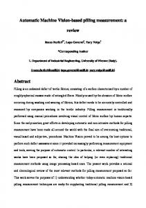
Figure 1: Hardware structure of the automatic recognition of the indicating value of the pointer gauge.
Image
Image
acquiring
preprocessing
Pointer and scale marks detection
Automatic
Gauge
reading
reading
identification
output
Detection
Preprocessing gauge image
of pointer
Reading identification
and scale
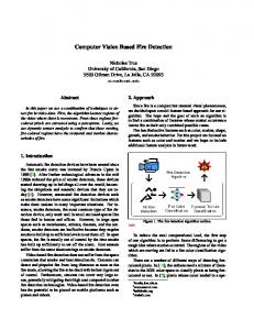
Figure 2: The image processing procedure of the automatic recognition of the indicating value of the pointer gauge.
is adopted to obtain the indicating value of the gauge by comparing the pointer direction with the position of the scale marks. Since the indicating value is determined by comparing the pointer direction and the locations of the scale marks, this approach is also suitable for gauges wherein the scale marks are unevenly distributed. Therefore, the proposed approach is, in fact, a general approach for gauge calibration.
2. Related Work 2.1. Configuration of Hardware System Used in Gauge Verification. The hardware system used in gauge verification generally comprises the following configuration [2–5] which is shown in Figure 1. During the working process, the high precise gauge and the calibrated gauge are placed on the worktable. A computer sends impulse signals to the motor driver. Therefore, the stepping motor is controlled to make the worktable move to allow for the adjustment of the location of the gauge, so that the gauges can be appropriately placed in the camera’s view, while the standard signal source sends reference signals to the calibrated pointer gauge and the high precise gauge. The indicating value of the high precise gauge is treated as standard data. Next, computer vision is applied to automatically recognize the values indicated by the calibrated and standard gauges. Finally, a comparison is made between the two values and the verification result is reached. For some other pointer gauges, the standard data produced by the reference signal generator is directly inputted
into the computer by the other signal-acquisition equipment. The verification result is achieved by comparing the standard data with the indicating value of the calibrated gauge, which is extracted using computer vision. 2.2. The Process of Automatic Reading of the Pointer Gauge Based on Computer Vision. Figure 2 shows the procedure of the image processing used to recognize the pointer gauge value. First, to improve the image quality, the gauge image has to be preprocessed by means of noise suppression and image enhancement. Next, image processing and analyzing methods are used to detect the pointer and scale marks. According to the pointer direction and the location of scale marks, the value indicated by the pointer gauge can be detected. Finally, the indicating value results are outputted. Therefore, the automatic recognition methods of the gauge indicating value mainly include three parts: (1) image preprocessing aimed to improve image quality and suppress noise, (2) gauge pointer and scale marks detection based on image processing and analyzing, (3) automatic recognition of the pointer gauge indicating value. 2.3. Related Work of the Pointer Gauge Indicating Value Detection. In the existing literature, the pointer gauge image should be preprocessed to remove noise or enhance
Mathematical Problems in Engineering the image, especially for the images extracted from industrial fields. Image preprocessing improves the image resolution. Thus, it is easier to detect the features relating to pointer and scale marks by means of image analyzing. Image preprocessing of the pointer gauge mainly comprises two parts. First, image preprocessing is used to filter out interference and noise that result from the change of environment. For example, in [6], the homomorphic filtering method was adopted to process the gauge image that has a large area of glare and reflection. Second, image preprocessing is used to correct an image distortion caused by camera imaging or different shooting angles. For instance, [7] discussed how to reduce the reading error when the gauge dial was uneven with the camera lens surface. The papers [8, 9] proposed an intelligent method of gauge value reading to avoid the influence of imaging distortion; this method was able to correct the angle between the pointer and the zero-scale marks and the angle between the zero-scale marks and the other longer scale marks. It also adopted the Newton interpolation method to approximate the functional relationships between the pointer angle and its indicating value. After image preprocessing, image segmentation should be implemented to obtain a binarization image, wherein the threshold-segmentation method is always applied [10–13]. In the following step, image thinning needs to be conducted in the binarization image to achieve a one-pixel-wide pointer image. Then, straight-line fitting is used to detect the pointer. So the key point of the automatic recognition of the gauge indicating value is the detection of the pointer and scale marks. In the existing literature, several methods for pointer detection, such as subtraction method, the template matching method, the Hough transform method, and the central projection method, were proposed. In the subtraction method [4, 14, 15], two gauge images with roughly the same backgrounds were taken by camera, while the pointer pointed toward a different scale. When one image was subtracted from another one, there were only two pointers left in the difference image. Next, the difference image was segmented to detect the pointer. Finally, the gauge’s indicating value could be obtained by calculating the position of the pointer and scale marks. The subtraction method was easily implemented by means of image subtraction. However, the different image not only reserves the pointer target but also leaves out a lot of noise due to the influence of illumination. Therefore, in many cases, the subtraction method does not produce reliable results. In the template feature method [16], the features that represent the pointer and its direction, such as shape, area, and gray distribution, formed a multiple parameters template used to match the pointer in the gauge image for pointer detection. Since the template comprises multiple cues of the pointer and its direction, the template feature method could avoid the influence of an uneven illumination and other environmental changing factors. However, the process of a template match is too complicated to accurately detect the pointer. The Hough transform method has often been used in pointer detection. In [17, 18], after edge detection and image thinning in the gauge image, the Hough transform method
3 or its improved version was applied to detect the pointer by fitting the pointer edge. The Hough transform method could achieve good results for the pointer gauge that has many words and symbols on the dial. In [19, 20], a novel pointer detection method, called central projection, was described. The main idea of the central projection method was to search for the pointer location by means of calculating the projection from the feature points to the known central point. Every projection value corresponded to the angle of the straight line that connected the projection and central points. There must be an angle that corresponds to the largest number of projection points and represents the pointer. Hence, the central projection method was always used to determine the location of the gauge pointer. The least squares method [21] was also a straight-line fitting method, just like the Hough transform method, which was used to detect the pointer. Compared with the Hough transform method, the least squares method required fewer calculations. After the pointer was detected, angle and distance methods [22] were always used to determine the indicating value of the point gauge. The angle method recognized the indicating value by calculating the deflection angle between the detected pointer and the zero-scale mark, according to the formula 𝑀 × 𝛽/𝛼. Here, 𝑀 was the range, 𝛼 was the premeasured angle between the maximum- and zero-scale mark, and 𝛽 was the angle between the current pointer and zero-scale mark. The distance method [23] obtained the indicating value by calculating the distance between the pointer and nearest scale mark. In this method, each scale reticule was located and labeled with the corresponding scale number in a twodimensional coordinate system. If the distance between the pointer and each reticule is as follows: 𝐴𝑥 + 𝐵𝑦𝑖 + 𝐶 , 𝑑𝑖 = 𝑖 √𝐴2 + 𝐵2
(1)
then the indicating value of the pointer is 𝑆𝑛 = 𝑆𝐿 +
𝑑1 × (𝑆𝐻 − 𝑆𝐿 ) . 𝑑1 + 𝑑0
(2)
Here (𝑥𝑖 , 𝑦𝑖 ) is the coordinate of the points in the scale marks, 𝑑𝑖 is the distance between the point and the line 𝐴𝑥 + 𝐵𝑦 + 𝐶 = 0, 𝑆𝑛 represents the indicating value of the pointer, 𝑆𝐻 and 𝑆𝐿 are the values of the scale marks which are located on both sides of the pointer, and 𝑑1 and 𝑑0 are the distance between the pointer and the nearest scale marks on both sides, respectively. The angle method is simpler than the distance method, but it is unsuitable for the pointer gauge in which the scale is uneven.
3. Overview of Our Work As mentioned above, the current methods for gauge reading recognition are limited in terms of their practical application, mainly due to two deficiencies. (1) The existing methods were all implemented in the global gauge images. Therefore, the pointer and scale marks segmentation cannot be accurately
4 conducted when there is some interference or where there is some complex writing on the gauge dial. (2) In many studies, the scale marks are not precisely detected. Hence, the indicating value of the pointer gauge with an uneven scale cannot be recognized. This study aims to overcome the shortcomings of the existing methods. As its contextual application, it also aims to improve the calibration of the pressure gauge and develop an automatic recognition method of pointer gauge readings based on machine vision. This method implements a scheme that takes detection from coarse to fine in terms of the pointer and scale marks detection. First, the pointer gauge’s dial region is located in a global image. Then, the dial’s annular scale region is located. In the following steps, the scale marks are detected in the annular scale region and the pointer is detected in the dial region. Finally, based on the results of the detection of the pointer and scale marks, the improved distance method is used to recognize the gauge’s value. Since the improved distance method is implemented from the coarse region to the fine target, it has a strong ability for suppressing interference. Since the indicating value is obtained from the pointer and scale marks detection, the method is also suitable for reading the gauge whose scale marks are unevenly distributed. 3.1. Machine Vision Based Pressure Gauge Verification System. Metrological departments usually calibrate pressure gauges with piston manometers. In this case, the standard pressure output of piston manometers, given by manually added weights, is passed on to the tested pressure gauge. Then, the qualification of the pressure gauge is determined through reading, analysis, and comparison of the indicating value. In general, verification personnel manually handle this process through observation by recording and analyzing the indicating value of the gauge panel. Many problems still exist with this verification method. They include (1) low accuracy and repeatability in human visual observations and (2) poor work efficiency, due to the large workload of verification personnel. Hence, development of an automatic verification method for the pressure pointer gauge will boost the advancement of the technology used in their production and verification capabilities. The system composition for pointer pressure gauge verification is shown in Figure 3. We can see that images of pointer gauges are obtained through a camera and processed and analyzed by computer, wherein the indicating values of the standard pressure gauge and the test gauge are detected and recognized. The final results of the gauge reading will be displayed on a monitor to operators and reach a verification conclusion based on the analyses of the above readings. The detection software also has such multifunctions as the storage of historical data, graphical display, and image switching to realize the automatic verification of pointer gauges. 3.2. Introduction of Our Work. In this study, a new automatic recognition method of the pointer gauge that indicates value is proposed. Figure 4 shows a block diagram of this method. In general, the computer vision based automatic recognition method of indicating value comprises two parts. One
Mathematical Problems in Engineering Piston gauge Calibrated gauge Camera Standard gauge
Image capture card Display
PC
Figure 3: Schematic of a machine vision based pressure gauge verification system.
part is the detection of the indicating value of the pointer gauge. This mainly includes the scale detection and the pointer detection, which refer to the location of the dial region and the dial center, the determination of the annular scale region in the dial, the scale detection, and the pointer detection. The other is the automatic recognition of the reading. Namely, it makes the final judgment of the gauge reading according to the detected direction of the pointer and the distribution of the scale marks. As seen in Figure 4, the automatic recognition of the indicating value, proposed in this paper, falls into five steps. (1) The dial region and its center location: first, in the entire image, the dial region can be determined by semi-interaction (using the mouse to drop down the box in the image). The pixel point with the biggest gray value is searched out in the dial region and taken as the seed point of the region growing method used to produce the circular region in the dial. In the process of the region growing method, the similarity threshold value between the pixel points is automatically determined. Finally, according to the results of the region growing method, the radius and center of the circular dial are obtained. (2) Determination of the scale region in the dial: the image coordinate is first converted into the polar coordinate with the dial center as its origin, which is used to express the coordinate of each pixel in the image. Then, by comparing the pixel sum of the low gray value with that of the high gray value in the annular region, the annular scale region in the dial is determined. And finally, it is copied into a new image as the annular scale region. (3) The scale marks are detected using the central projection method. In the newly generated annular scale region image, first, the scale mark segmentation is conducted by the OSTU method to form the binarization scale image. Then, the angle of each line that links the black pixel with the circle center is calculated, and the number of each angle is obtained. The angles with large numbers (connecting line) in a narrow angle range correspond to the thick scale marks (main scales) on the dial. Thus, the angles of the scale marks in the scope of 0∘ –360∘ are obtained.
Mathematical Problems in Engineering
5
Search the pixel point with maximum gray in the dial region as the seed
Convert the image into the polar coordinates with the dial center as its origin center
Conduct region growing from the seed point and adaptively determine the similarity principle between the pixels
Determine the annular scale region by comparison between the pixel sum of low gray value and that of high gray value
Obtain the center and radius of circular dial region by region growing
Copy the circular scale region established into a new image
Dial region and center location
Utilize the Canny operator to perform border detection on the dial image
Use the adaptive threshold value to perform the Hough transform on dial border image and fit the gauge pointer contour
Calculate the pointer direction within the scope of 0–360 degrees. Detection of gauge pointer by Hough transform
Determination of annular scale region in the dial
Segment the image in annular scale region by OSTU to obtain the binarization scale image
Traverse the black pixel points in the image, link each black point to the circle center, and then calculate the angle of the connecting line to get that of each coarse scale mark
Obtain the scale in the scope of 0–360 degrees.
Scale detection by central projection method
Calculate the indicating value according to the pointer direction and the dial scale distribution The indicating value reading
Figure 4: The flow chart of the pointer gauge indicating value recognition.
(4) Pointer detection: first, the Canny operator is used to implement the border detection. Then, the Hough transform method is used to fit the detected edge and obtain the pointer contour. Finally, the pointer direction is obtained according to the center position and the pointer contour. (5) The indicating value is calculated according to the pointer direction and the dial scale distribution.
4. Indicating Value Recognition Approach of Pointer Gauge 4.1. Pointer Gauge Indicating Value Detection. As mentioned above, the detection of the indicating value is achieved through the scale and pointer detection. As for the scale detection, first, the gauge center and dial region should be located, followed by the extraction of the annular scale region
6
Mathematical Problems in Engineering
(a) Typical pointer gauge
(b) The results of the dial region growing method
Figure 5: The diagram of the dial region growing results.
and the scale mark detection. Finally, the detection of the pointer direction is performed. 4.1.1. Dial Region and Its Center Location. As for the detection of the indicating value, first the gauge pointer and its direction should be detected to determine its rotation center. In general, the gauge’s dial center is the pointer’s rotation center. Hence, first, the dial center should be detected. In this study, the circular dial region is detected for determining the dial center. As is shown in Figure 5(a), typically, there are the labels, words, and scale marks in the circular dial. Therefore, it is difficult to confirm the circular region of the dial by such segment methods as the border and threshold values. In view of the above, this paper introduces the adaptive-regiongrowing method to locate the gauge’s circular region and, further, to obtain its dial center. The specific steps are as follows. (1) The placement of the seed [24]: since the dial is usually white, the region with a high gray level or the pixel point with the highest gray level in the gauge is certainly located at the part where the dial is. Therefore, the latter is selected as the seed point of the region growing. (2) Subject to the similarity of the pixel gray level, the expansion of the dial region is conducted from the seed point. However, it is hard to fix an appropriate similarity threshold value of the gray level between pixels. As is shown in Figure 5(b), the circular dial region cannot be completely produced with a small threshold value, while an oversized dial region will be generated with a large threshold value. This study proposes an adaptive method to determine the similarity threshold value of the gray level; the concrete process is as follows. (A) A small similarity threshold value, 𝑇, of the gray level is empirically chosen, and then, the dial region growing method is conducted from the seed point.
(B) The ratio of the circumscribed rectangle’s length and width of the newly generated dial region is calculated to detect whether it is in the 0.95–1.05 range. (C) If the ratio of the length and width fails to meet the conditions in (B), the similarity threshold value would be increased with a certain step length (𝑆), and the first step, (A), would continue to conduct the region growing from the seed point. However, if it meets the conditions in (B), the growing region will be the circular dial region, the center of the circumscribed rectangle will be the circle center, and the smaller value between the length and width will be the diameter of the circular region (Figure 6). 4.1.2. Polar Coordinate Based Scale Region Location (1) Image in Polar Coordinates. In general, in light of the circular permutation, the pointer gauge scale marks are distributed around the center. Therefore, to correctly and expediently show where the scale marks in the image are, the polar coordinate system is utilized to position the pixels in the image. In this study, a conversion from the image coordinates into the polar coordinates is performed. This means that the pixel coordinates, expressed by the rectangular image coordinate system, are converted into those expressed by polar coordinates. The polar coordinates defined in this study are shown in Figure 7, the circle center being its origin. (2) Detection of the Scale Region in the Dial. The procedure for scale region detection based on the adaptive threshold method is as follows. (A) The circular dial radius detected in Section 4.1.1 is taken as the initial radius 𝑅, its decreasing step length being 𝑏 and the initial 𝑛 = 1. In the gauge dial, the gray value difference between the scale marks and dial background is generally rather large. Therefore, the adaptive threshold value method can be adopted to segment the scale. In the polar coordinate, the annular binarization image is gained by employing
Mathematical Problems in Engineering
7
(a)
(b)
(c)
(d)
Figure 6: The region growing results under different pixel similarity threshold values.
90∘
120
∘
30
150∘
180
white pixel points in the region between 𝑅 − (𝑛 + 1) ∗ 𝑏 and 𝑅 is computed and denoted by 𝑟2 .
60∘
(C) If 𝑟1 is obviously different from 𝑟2 , the inner radius and the outer radius of the scale region would be 𝑅 − (𝑛 + 1) ∗ 𝑏 and 𝑅, respectively.
∘
∘
0
∘
330∘
210∘ 240∘
270
∘
300∘
Figure 7: Schematic of the polar coordinate.
the OSTU method [25] to perform the binarization segmentation in the annular region. (B) The ratio between the number of black and white pixel points in the annular binarization region between the radius 𝑅 and 𝑅 − 𝑛 ∗ 𝑏 is calculated and denoted by 𝑟1 . After reducing the inner radius, according to the step length 𝑏, the ratio between the number of black and
(D) If 𝑟1 is approximated to 𝑟2 , the annulus between 𝑅 − (𝑛 + 1) ∗ 𝑏 and 𝑅 would still be in the circular scale region. At this moment, let 𝑛 = 𝑛+1; the ratio between the number of black and white pixel points in the annulus between 𝑅 − (𝑛 + 1) ∗ 𝑏 and 𝑅 is computed and is still denoted by 𝑟2 . Then, go to (B) (Figure 8). After obtaining the annular scale region in the above polar coordinate, the scale region is selected on the basis of angle and radius and copied into a new image, called the scale mark region image 𝑀 (Figure 9). 4.1.3. Scale Mark Detection Based on the Improved Central Projection Method. In the newly generated image, 𝑀, which is the annular scale region, the OSTU method is adopted to segment the scale marks to form the binarized scale image. In this image, the pixel value of the scale mark is 0 (black) and those in other places are 255 (white). Each black pixel point and the circle center are linked, and the slope, 𝐾, of the connecting line is calculated according to the formula 𝑘 = tan 𝛼, wherein 𝛼 is the angle between the 𝑥-axis and
8
Mathematical Problems in Engineering
(a)
(b)
(c)
Figure 8: Schematic of scale mark region detection.
(a)
(b)
Figure 9: The scale mark region diagram and its binarized image.
Mathematical Problems in Engineering
9 y 4 3 2
x
0
1 −4
−3
−2
−1 0
1
2
3
4
x
−1 −2 −3 −4 y (a) Schematic of the image coordinate system
(b) The rectangular coordinate system
the connecting line between the black pixel point and the circular center. Due to the origin of the image coordinate being in the top left corner and the 𝑦-axis running downward, it is inconvenient to denote the central angle within the scope of 0∘ –360∘ . Therefore, in this study, the rectangular coordinate system, with the image center as its origin, is introduced to express the angle between the black pixel point on the scale mark and the circle center, instead of the image coordinate system. As is shown in Figure 10, the angles between the black pixel point and the circle center are in the 0∘ –360∘ range. After calculating the number for angle 𝛼, the angle with a large number (connecting lines) in a small angle range is that of the thick scale mark (main scale) on the dial. The steps to detect the scale mark by central projection are detailed as follows. (1) The black pixel point and the image central point, that is, the circle center (𝑥0 , 𝑦0 ) in the new image, are linked to determine the slope 𝑘, which is converted to an angle according to the following formula: 180 (3) . 𝜋 (2) As shown in Figure 10, the image coordinate system is transformed to a rectangular one. The angle 𝛼, following formula (4), is converted into an angle in the rectangular coordinate: 𝜃 = −𝛼 𝑖 < 𝑟, 𝑗 > 𝑟, the first quadrant 𝛼 = arctan (𝑘) ∗
𝜃 = 180 − 𝛼 𝑖 < 𝑟, 𝑗 < 𝑟,
the second quadrant
𝜃 = 180 − 𝛼
𝑖 > 𝑟, 𝑗 < 𝑟,
the third quadrant
𝜃 = 360 − 𝛼
𝑖 > 𝑟, 𝑗 > 𝑟,
the forth quadrant.
Occurrence times
Figure 10: Schematic of the image coordinate system and the rectangular coordinate system.
0
𝜃1
𝜃2 𝜃3 Angle (deg)
𝜃4
Figure 11: The angle histogram.
(3) An angle histogram is generated by recording the occurrence frequency of each angle. Figure 11 shows the angle histogram. (4) The angle with the most occurrence times in the histogram is selected and denoted by max; all the angles whose occurrence times are more than max /2 are found. The occurrence times of the angles are denoted by 𝑓(𝜃). Here, 𝜃 represents the angles that occur more than max /2. (5) For every angle 𝜃, we calculate the weighted average value anglemean(𝑚), according the following to formula: anglemean (𝑚) =
𝑓 (𝜃 + 1) ∗ (𝜃 + 1) + 𝑓 (𝜃) ∗ (𝜃) + 𝑓 (𝜃 − 1) ∗ (𝜃 − 1) . 𝑓 (𝜃 + 1) + 𝑓 (𝜃) + 𝑓 (𝜃 − 1)
(4) (5) Here, 𝑚 is the sign of the angle.
10
Mathematical Problems in Engineering y
𝛼2
𝛼3
Thick scale marks
𝛼1 𝛼0 x
Figure 13: Schematic of pointer fitting and its direction.
conforming to 𝑑 < 2𝑟/10 are picked out. Here, 𝑟 is the diameter of the dial. (3) The angle of each straight line in (1) is calculated according to formula (8) and stored into an array angle[]:
Figure 12: The location of the thick scale marks.
(6) Calculate specific value 𝑃, according to the following formula: anglemean (𝑚) . 𝑃= anglemean (𝑚 + 1)
(6)
If 𝑃 is within the 0.9–1.1 range, anglemean(𝑚) is the angle of the thick scale mark. All the angles sorted out successively are taken as 𝛼0 , 𝛼1 , 𝛼2 , . . ., which correspond to the thick scale marks. Therefore, the thick scale marks are located on Figure 12. 4.1.4. Improved Hough Transform-Based Pointer Detection. The edge detection is implemented in the pointer gauge image, using the Canny operator to obtain the edge image of the gauge. Then, the Hough transform method is adopted to fit the straight line in the image to obtain all the straight lines among which the pointer border is included. Finally, only the pointer border can be determined by excluding the other straight edges. (1) The Hough transform method is adopted to fit the straight line and find all the straight lines in the image. In addition, each straight line described in the image coordinate system by 𝑦 = 𝑘𝑥 + 𝑏 is calculated. (2) The distance, 𝑑, from the circle center, (𝑥0 , 𝑦0 ), to the straight line is calculated according to the following formula: 𝑦0 − 𝑘 ∗ 𝑥0 − 𝑏 𝑑= . √1 + 𝑘2
(7)
Based on prior knowledge, we know that the distance from the circle center to the straight line of the pointer is much less than the diameter of the dial; all the straight lines
𝜑=
arctan (𝑘) ∗ 180 . 𝜋
(8)
(4) As the angles of the pointer direction are acute ones, generally in the range of 2∘ ∼ 10∘ , the angle Δ𝜑 is calculated subject to the following formula: Δ𝜑 = angle [𝑛] − angle [𝑛 + 1] .
(9)
If it is in the situation where 2 < Δ𝜑 < 10, the straight line should be selected as one side of the pointer. Therefore, both lines where the two sides of the pointer lie can be found. (5) According to the straight lines of the two sides, the pointer direction can be determined. 4.2. The Pointer Gauge Indicating Value Recognition. As is shown in Figure 11, the intersection point, 𝐺, of the two straight lines of the pointer border is calculated and then linked to the circle center 𝑂(𝑥0 , 𝑦0 ). The angle of the line, 𝑂𝐺, is calculated. In accordance with the position of the intersection point, 𝐺, the angle, 𝛽, in the rectangular coordinate system is computed according to formula (1) (Figure 13). According to the angle, 𝛽, the readings, 𝐷0 , 𝐷1 , . . . , 𝐷𝑛 , corresponding to each thick scale mark are obtained. Based on the angle that corresponds to the thick scale mark and its number, 𝑛, which is detected in Section 4.1.4, the pointer reading can be determined according to formula (10).
Mathematical Problems in Engineering
11 Table 1: Experimental samples.
Sample name The pressure gauge with many labels and a lot of writing on the dial. Flow gauge with the uneven scale.
Image resolution 1000/750 500/500
Sample character A lot of writing on the dial, which may influence the location of the dial center and the pointer segmentation. Uneven distribution of the scale marks.
The scale within the adjacent thick scale marks is divided by linear interpolation: 𝑆indicating value 𝛼 − 𝛽 0 { (𝐷 − 𝐷0 ) , { { 𝛼0 − 𝛼1 1 { { { { 𝛼 − 𝛽 { { { { 1 (𝐷2 − 𝐷1 ) + 𝐷1 , { = { 𝛼1 − 𝛼2 { .. { { . { { { { { { { 𝛼𝑛−1 − 𝛽 { (𝐷𝑛 − 𝐷𝑛−1 ) + 𝐷𝑛−1 , { 𝛼𝑛−1 − 𝛼𝑛
𝛼0 < 𝛽 < 𝛼1 𝛼1 < 𝛽 ≤ 𝛼2
𝛼𝑛−1 < 𝛽 ≤ 𝛼𝑛 . (10)
Here, 𝛼0 , 𝛼1 , 𝛼2 , . . . , 𝛼𝑛 are the angles that correspond to the thick scale marks.
5. Experimental Results and Analysis To verify the effectiveness of the proposed approach, a series of experiments are conducted to test its performance. 5.1. Experiment Design. The experiments include two parts. First, the images of the different kinds of pointer gauges are selected to conduct the simulation experiments and verify the effectiveness and applicability of the approach. Then, the pressure gauge calibration system, which is composed of a float gauge, high precise pressure gauge, test pressure gauge, camera, and computer, is established to verify the actual performance of this approach in the pointer gauge calibration. 5.2. Part One of the Experiments: Reading Identification of the Various Pointer Gauges 5.2.1. Samples Selection. As can be seen in Table 1, two groups of representative samples are selected for the experiment. They include the pressure gauge with a lot of writing on the dial and the flow gauge with an uneven scale. 5.2.2. Experimental Results and Analysis. In this part of the experiment, we adopt the proposed approach to the automatic recognition of the indicating value of the above mentioned two types of gauges. To verify the effectiveness of the proposed approach, Figures 14 and 15 illustrate the experimental results of each step. Figure 14(a) is the original pointer gauge image. From Figure 14(a), we can see that the pointer and scale marks
The purpose of sample selection Verify the robustness of the algorithm and the capability of resisting interference. Verify the universality of the algorithm.
cannot be directly detected by segmentation methods since there is a lot of writing on the dial. Therefore, the proposed approach applies an idea that conducts a coarse-to-fine search. The dial and scale regions are located first, since they are more easily detected than the pointer and scale marks. As shown in Figures 14(c) and 14(d), the dial region is located using the adaptive-region-growing method, and the scale region is detected under the polar coordinate system. Then, in both regions, the pointer and scale marks are accurately detected. As shown in Figures 14(e) and 14(f), the improved Hough transform method is adopted to detect the pointer and the improved central projection method is used to detect the scale marks. The location of the thick scale marks is determined according to the angle histogram generated from the central projection of the scale marks. Their indicating values are given according to the location of the thick scale marks. The scale values within any two adjacent thick marks are determined by linear division. According to the direction of the pointer and the location of the scale marks, the angle method, which is adopted in the adjacent thick scale marks, is used to indicate the pointer gauge value. The proposed approach detects the pointer direction and the scale marks location, respectively. In Figures 15(e) and 15(f), it can be seen that the location of the scale marks is precisely obtained by the angle histogram and the pointer is detected in the dial region. Based on the location of the scale marks and the pointer direction, the distance between the pointer and the adjacent scale marks can be calculated using the distance method; then, the pointer indicating value can be estimated. Therefore, whether or not the distribution of the scale is even, the proposed approach is able to precisely detect the gauge’s indicating value, while the most current existing methods cannot. 5.3. Part Two of the Experiments: The Recognition of the Float Pointer Gauge Indicating Value 5.3.1. The System and Procedure of Experiments. To verify the performance of the practical application of the proposed approach in practical application, the float gauge is used as the pressure gauge verification system. The type of float gauge is Y-047. The main technical parameters of the float gauge are described as follows. The range of output pressure is 0.01– 0.25 MPa; the accuracy class is ±0.05%; the rated pressure is 0.5 MPa; and the standard weights are from 0.01 MPa to 25 MPa. A high-precision gauge is used as the standard pressure gauge whose accuracy class is 1.5. The test gauge is a gauge with general accuracy. A visual detection system is established in front of the float gauge. An optical lens,
12
Mathematical Problems in Engineering
(a) The original gauge image
(b) The dial region of the manual interception
(c) Detection results of dial center and dial region
𝛼0 𝛼1 𝛼2 𝛼3 𝛼4 𝛼5 𝛼6 𝛼7 𝛼8
(d) Detection results of scale region
𝛼9 𝛼10
(e) Angle histogram for scale marks detection
(f) Results of the pointer and scale marks detection
Figure 14: The detection results of the pointer gauge with a lot of writing on the dial.
whose focal length can be adjustable from 10 to 20 mm, and a 500-megapixel HD CMOS camera with a 60 fps frame rate are applied as image sensors. The system is equipped with a coaxial light source, which is placed on the camera lens. The hardware configuration of the computer used in this experiment is Inter Pentium(R) Dual, CPU E2200, and
2.2 GHz. The programming environment is VS2010. The verification system of the pointer gauge that is based on computer vision is shown in Figure 16. The camera used in the experiments takes images of the high-precision standard gauge and the test gauge. The proposed approach is adopted to detect the indicating value of both standard and test gauges.
Mathematical Problems in Engineering
13
(a) Original gauge image
(b) Dial region by manual interception
(c) Detection results of dial center and dial region
(d) Detection results of scale region
𝛼0
𝛼1
𝛼2
(e) Angle histogram for scale marks detection
𝛼3 (f) Results of the pointer and scale marks detection
Figure 15: The detection results of the pointer gauge with an uneven scale.
According to the gauge calibration regulations, the experiment procedure is as follows. First, a positive stroke is conducted. Here, the float gauge’s output is increased by gradually loading the weights, while the gauge’s indicating value is increased. At each indicating value test point, the camera takes images of both the standard pointer and test gauges. The proposed approach is to use the images to recognize the indicating values. Then, a negative stroke is conducted, of which the process is that the float gauge output is reduced from the highest test point by gradually unloading the weights, while the gauge’s indicating value is accordingly reduced. An image of each test point is taken to recognize the indicating values.
5.3.2. Experimental Results and Analysis. The experimental results are shown in Figures 17 and 18. The gauge’s upper limit is 0.25 MPa; the lower limit is 0 MPa. Whatever the experiment is, in the positive or negative stroke, the float gauge output intervals are 0.025 MPa. The detection results for the indicating values of the standard and test gauges are shown in Tables 2 and 3, respectively. As can be seen from the experimental results, the proposed approach is applicable to the pressure gauge verification. The indicating values of the test and standard gauges can be obtained by the proposed approach, instead of being obtained through manual observation. The test gauge calibration is completed by comparing the indicating value
14
Mathematical Problems in Engineering
(a)
(b)
Figure 16: The experimental system of gauge test.
paper; the approach can be used for pressure gauge verification.
Figure 17: The standard gauge results.
(2) The approach proposes a stable frame about the reading identification of the pointer gauge. From big region to small target, the approach first locates the scale and the pointer region. Then, it precisely segments the pointer and scale marks in the target area. Finally, the indicating value of the gauge is obtained based on the direction of the pointer and the distribution of the scale marks. This framework is a general recognition method of a pointer gauge based on computer vision and has good interference immunity. However, to achieve more satisfactory results in its practical application, each step has to be improved. For example, in the process of locating of the dial region based on the region growing method, many factors need to be considered to determine whether the use of this method should be terminated. (3) In its practical application, the image preprocessing method should be used along with the proposed method, so as to obtain more satisfactory results, especially for some industrial field applications.
6. Conclusion Figure 18: The test gauge results.
of the test gauge with that of the standard gauge. From the experimental results in Tables 2, 3, and 4, comparing the visual data with the manual reading, we can see that the detection results of the indicating value based on computer vision are more accurate, valid and have more significant digits and a faster detection speed. 5.4. Experimental Conclusion. From the above experimental results, we can draw the following conclusions. (1) The indicating value of the pointer gauge can be effectively detected using the method proposed in this
This study proposes a pointer gauge automatic reading approach based on computer vision. The approach aims at overcoming the defects in the current pointer gauge automatic reading approach and the application of pressure gauge verification. According to the framework of the proposed approach, which is conducted from big-region segmentation to small-target detection, first, the target region in the dial is located. Then, the pointer and scale marks are detected in this region. Finally, the indicating gauge value is obtained. As such, the proposed approach has good interference immunity and is applicable for both gauges with and without evenly distributed scale marks. The approach can be widely applied to the reading identification of different types of pointer gauges. The proposed method is robust and precise enough to be used in pointer gauge verification. However, in some practical
0 0.025 0.050 0.075 0.100 0.125 0.150 0.175 0.200 0.225 0.250
The pressure of checkpoint (MPa)
Positive stroke Visual Manual detection reading 0 0 0.024343 0.024 0.048727 0.049 0.074386 0.075 0.100408 0.099 0.125060 0.125 0.149762 0.15 0.174613 0.175 0.198316 0.2 0.225053 0.224 0.249344 0.249
Error 1 (visual detection-weights value) 0 0.000657 0.001273 0.000614 0.000408 0.000060 0.000238 0.000387 0.001684 0.000053 0.000656
The indicating value of standard gauge Error 2 (manual Negative stroke reading-weights Visual Manual value) detection reading 0 0 0 0.001 0.025610 0.025 0.001 0.049761 0.05 0 0.075876 0.076 0.001 0.100147 0.1 0 0.125482 0.126 0 0.150647 0.151 0 0.174720 0.176 0 0.201540 0.201 0.001 0.225149 0.225 0.001 0.249344 0.249
Table 2: The standard gauge detection results. Error 1 (visual detection-weights value) 0 0.000610 0.000240 0.000876 0.000147 0.000482 0.000647 0.000280 0.001540 0.000149 0.000660
Error 2 (manual reading-weights value) 0 0 0 0.001 0 0.001 0.001 0.001 0.001 0 0.001
0 0.26/0.24 0.51/0.10 0.25/0.35 0.16/0.06 0.024/0.19 0.095/0.26 0.155/0.11 0.674/0.62 0.02/0.06 0.26/0.26
The cited error (absolute error/range)
Mathematical Problems in Engineering 15
0 0.025 0.050 0.075 0.100 0.125 0.150 0.175 0.200 0.225 0.250
The pressure output of the checkpoint (MPa)
Positive stroke Visual Manual detection reading 0 0 0.025650 0.026 0.050200 0.051 0.075470 0.076 0.100100 0.101 0.126000 0.126 0.150900 0.152 0.177626 0.173 0.202263 0.203 0.226146 0.227 0.249057 0.252
Error 1 (visual detection-weights value) 0 0.000650 0.000200 0.000470 0.000100 0.001000 0.000900 0.002626 0.002263 0.001146 0.000940
The indicating value of tested gauge Error 2 (manual Negative stroke reading-weights Visual Manual value) detection reading 0 0 0 0.001 0.027084 0.028 0.001 0.051623 0.052 0.001 0.077778 0.078 0.001 0.101095 0.102 0.001 0.126106 0.127 0.002 0.151486 0.153 0.002 0.177678 0.179 0.003 0.202445 0.204 0.002 0.226223 0.228 0.002 0.249057 0.252
Table 3: The test gauge detection results. Error 1 (visual detection-weights value) 0 0.002084 0.001623 0.002778 0.001095 0.001106 0.001486 0.002678 0.002445 0.001223 0.000940
Error 2 (manual The cited errors reading-weights (the absolute error/range) value) 0 0 0.003 0.26/0.83 0.002 0.08/0.65 0.003 0.19/1.11 0.002 0.04/0.44 0.002 0.4/0.44 0.003 0.36/0.59 0.004 1.05/1.07 0.004 0.90/0.978 0.003 0.46/0.49 0.002 0.38/0.38
16 Mathematical Problems in Engineering
The indicating value of visual detection The pressure output Positive stroke Relative error 1: Error 1: of the checkpoint Standard gauge: Tested gauge: 𝛿 − 𝛿 (MPa) (𝛿 − 𝛿 )/𝛿 (%) (MPa) 1 2 1 2 1 𝛿2 (MPa) 𝛿1 (MPa) 0 0 0 0 0 0.025 0.024343 0.025650 0.001310 5.37000 0.050 0.048727 0.050200 0.001473 3.02296 0.075 0.074387 0.075470 0.001080 1.45644 0.100 0.100408 0.100100 0.000308 0.30675 0.125 0.125060 0.126000 0.000940 0.75164 0.150 0.149762 0.150900 0.001140 0.75987 0.175 0.174613 0.177626 0.003010 1.72553 0.200 0.198316 0.202263 0.003950 1.99026 0.225 0.225053 0.226146 0.001090 0.48566 0.250 0.249344 0.249057 0.000287 0.11510
The indicating value of manual reading Positive stroke Relative error 2: Error 2: Standard gauge: Tested gauge: 𝜎 − 𝜎 (MPa) (𝜎1 − 𝜎2 )/𝜎1 (%) 1 2 𝜎1 (MPa) 𝜎2 (MPa) 0 0 0 0 0.024 0.026 0.002 8.333 0.049 0.051 0.002 4.082 0.075 0.076 0.001 1.333 0.099 0.101 0.002 2.02 0.125 0.126 0.001 0.8 0.15 0.152 0.002 1.333 0.175 0.173 0.002 1.1429 0.2 0.203 0.003 1.5 0.224 0.227 0.003 1.339 0.249 0.252 0.003 1.205
Table 4: Comparisons between manual reading and visual detection.
0 0.08202 0.03533 0.01225 0.02051 0.00706 0.01219 0.01440 0.01105 0.01230 0.01233
Comparison (error 1 − error 2)
Mathematical Problems in Engineering 17
18 applications, especially in the industrial field, it should be used by combining it with image preprocessing methods so as to achieve better effects. The improved approach can also be used for the pointer gauge whose dial is noncircular. Therefore, in the future we will conduct the following studies to complete the digitization work on the pointer gauge, so as to develop a general indicating value reading method. (1) The image preprocessing methods will be developed to eliminate the influence of stray or reflective light or to correct the image distortion caused by changes in the relative position between the camera and gauge. (2) A general automatic reading method will be developed for different types of pointer gauges, which can be used in various hardware systems and have a unified standard output format.
Mathematical Problems in Engineering
[9]
[10]
[11]
[12]
Conflict of Interests The authors declare that there is no conflict of interests regarding the publication of this paper.
Acknowledgments The work is supported by Beijing Key Discipline Development Program (no. XK100080537), the Beijing Natural Science Foundation (4122050), and Opening Project of Key Laboratory of Operation Safety Technology on Transport Vehicle, Ministry of Transport, China.
[13]
[14]
[15]
[16]
References [1] L. Yanwen, G. Jinfeng, Z. Hongwei, and R. Hui, “Detection system of meter pointer based on computer vision,” in Proceedings of the International Conference on Electronic and Mechanical Engineering and Information Technology (EMEIT ’11), pp. 908– 911, August 2011. [2] Z. Jun, F. Haiping, and K. Ming, “Automatic calibration of dial gauges based on computer vision,” Infrared and Laser Engineering, vol. 37, pp. 333–336, 2008. [3] M. K. Gellaboina, G. Swaminathan, and V. Venkoparao, “Analog dial gauge reader for handheld devices,” in Proceedings of the IEEE 8th Conference on Industrial Electronics and Applications (ICIEA ’13), pp. 1147–1150, June 2013. [4] F. C. Alegria and A. C. Serra, “Automatic calibration of analog and digital measuring instruments using computer vision,” IEEE Transactions on Instrumentation and Measurement, vol. 49, no. 1, pp. 94–99, 2000. [5] B. Sun, C. Zhang, Z. Liu, B. Qian, and H. P. Zhang, “Study of FPGA-based visual detection for pointer dial,” in Proceedings of the 26th Chinese Control and Decision Conference (CCDC '14), pp. 1467–1472, Changsha, China, May-June 2014. [6] G. Gui-fa, W. Ren-huang, and W. Huan, “A pretreatment of image based on reformative homomorphic filtering,” Journal of Guangdong University of Technology, vol. 26, no. 3, pp. 57–59, 2009. [7] D.-C. Luo, S.-C. Wang, H.-G. Zeng, Z.-Z. Li, and X.-M. Lu, “Design of recognition system of analog measuring instruments,” Laser & Infrared, vol. 37, no. 4, pp. 377–380, 2007. [8] H. Wen, Z. Teng, S. Yang, and S. Liu, “Intelligent reading method for analog meter based on computer vision,” Chinese
[17]
[18]
[19]
[20]
[21]
[22]
[23]
[24]
Journal of Scientific Instrument, vol. 28, no. 7, pp. 1234–1239, 2007. W. Qi, T. Xiling, D. Cheng, H. Yao, and F. Yanjun, “Automatic alignment system based on center point recognition of analog measuring instruments dial,” in Proceedings of the 39th Annual Conference of the IEEE Industrial Electronics Society (IECON ’13), pp. 5532–5536, IEEE, Vienna, Austria, November 2013. F.-J. Sun, T.-J. An, J.-Q. Fan, C.-P. Yang, and Z. Xu, “Study on the recognition of pointer position of electric power transformer temperature meter,” Proceedings of the Chinese Society of Electrical Engineering, vol. 27, no. 7, pp. 470–475, 2007. Z. Le, The research of indication recognition for dial instruments based on image processing [M.S. thesis], North China Electric Power University, Beijing, China, 2013. S.-H. Lu, Study on automatic test system for high precision pointer instrumeng based on machine vision [Dissertation for the Master Degree in Engineering], Harbin Institute of Technology, 2013. Q. Wang, Y. Fang, W. Wang, M. Wu, R. Wang, and Y. Fang, “Research on automatic reading recognition of index instruments based on computer vision,” in Proceedings of the 3rd International Conference on Computer Science and Network Technology (ICCSNT ’13), pp. 10–13, October 2013. Z. Shutao, Direct reading instrument calibration method based on computer vision [Ph.D. thesis], North China Electric Power University, Beijing, China, 2006. S. W. Wang and Y. W. Dai, “Automatic recognizing of multipointer’ water meter using image processing,” Chinese Journal of Scientific Instrument, vol. 26, no. 11, pp. 1178–1120, 2005. F.-J. Sun, T.-J. An, J.-Q. Fan, C.-P. Yang, and Z. Xu, “Study on the recognition of pointer position of electric power transformer temperature meter,” Proceeding of the CSEE, vol. 27, no. 7, pp. 70–78, 2007. B. Hemming and H. Lehto, “Calculation of uncertainty of measurement in machine vision case: a system for the calibration of dial indicators,” in Proceedings of the 18th IEEE Instrumentation and Measurement Technology Conference, pp. 665–670, Budapest, Hungary, May 2001. B. Chen and L. Jin, “A new meter dial indicator detection method based on center point projection,” Application Research of Computers, vol. 22, no. 1, pp. 246–248, 2005. J. Zetao, W. Shi, and L. Kewei, “An effective method on non-contact measurement for gauges with pointer,” Computer Application and Software, vol. 26, no. 4, pp. 281–285, 2009. J.-C. Yin, J. Lou, and H.-T. Zhao, “Vision system and its application in the auto door latch assembly line,” Techniques of Automation and Applications, no. 1, pp. 79–82, 2010. H. Zhou, H.-E. Xu, and C.-G. Geng, “Automatic checking of pointer automotive dashboard based on HIS model and Hough transformation,” Journal of Zhejiang University (Engineering Science), vol. 44, no. 6, pp. 1108–1113, 2010. J. Han, E. Li, B. Tao, and M. Lv, “Reading recognition method of analog measuring instruments based on improved hough transform,” in Proceedings of the IEEE 10th International Conference on Electronic Measurement and Instruments (ICEMI ’11), pp. 337–340, August 2011. C. Li, L. Yang, Z. Liu, and K. Li, “A new automatic seeded region growing algorithm,” in Proceedings of the 6th International Congress on Image and Signal Processing (CISP '13), vol. 1, pp. 543–549, Hangzhou, China, December 2013. S. Hengqiang and W. Changji, “A new algorithm based on supergreen features for ostu’s method using image segmentation,” in
Mathematical Problems in Engineering Proceedings of the World Automation Congress (WAC ’12), pp. 1–4, June 2012. [25] J. Xu, X. Sun, D. Zhang, and K. Fu, “Automatic detection of inshore ships in high-resolution remote sensingimages using robust invariant generalized hough transform,” IEEE Geoscience and Remote Sensing Letters, vol. 11, no. 12, pp. 2070–2074, 2014.
19
Advances in
Operations Research Hindawi Publishing Corporation http://www.hindawi.com
Volume 2014
Advances in
Decision Sciences Hindawi Publishing Corporation http://www.hindawi.com
Volume 2014
Journal of
Applied Mathematics
Algebra
Hindawi Publishing Corporation http://www.hindawi.com
Hindawi Publishing Corporation http://www.hindawi.com
Volume 2014
Journal of
Probability and Statistics Volume 2014
The Scientific World Journal Hindawi Publishing Corporation http://www.hindawi.com
Hindawi Publishing Corporation http://www.hindawi.com
Volume 2014
International Journal of
Differential Equations Hindawi Publishing Corporation http://www.hindawi.com
Volume 2014
Volume 2014
Submit your manuscripts at http://www.hindawi.com International Journal of
Advances in
Combinatorics Hindawi Publishing Corporation http://www.hindawi.com
Mathematical Physics Hindawi Publishing Corporation http://www.hindawi.com
Volume 2014
Journal of
Complex Analysis Hindawi Publishing Corporation http://www.hindawi.com
Volume 2014
International Journal of Mathematics and Mathematical Sciences
Mathematical Problems in Engineering
Journal of
Mathematics Hindawi Publishing Corporation http://www.hindawi.com
Volume 2014
Hindawi Publishing Corporation http://www.hindawi.com
Volume 2014
Volume 2014
Hindawi Publishing Corporation http://www.hindawi.com
Volume 2014
Discrete Mathematics
Journal of
Volume 2014
Hindawi Publishing Corporation http://www.hindawi.com
Discrete Dynamics in Nature and Society
Journal of
Function Spaces Hindawi Publishing Corporation http://www.hindawi.com
Abstract and Applied Analysis
Volume 2014
Hindawi Publishing Corporation http://www.hindawi.com
Volume 2014
Hindawi Publishing Corporation http://www.hindawi.com
Volume 2014
International Journal of
Journal of
Stochastic Analysis
Optimization
Hindawi Publishing Corporation http://www.hindawi.com
Hindawi Publishing Corporation http://www.hindawi.com
Volume 2014
Volume 2014