Materials and Design 90 (2016) 256–265
Contents lists available at ScienceDirect
Materials and Design journal homepage: www.elsevier.com/locate/jmad
Machines and control systems for friction stir welding: A review Nuno Mendes a, Pedro Neto b,⁎, Altino Loureiro b, António Paulo Moreira a a b
Robotics and intelligent Systems Group (ROBIS) INESC-PORTO, University of Porto, Rua Dr. Roberto Frias, 378, 4200-465 Porto, Portugal Department of Mechanical Engineering CEMUC, University of Coimbra, Polo II, Rua Luís Reis Santos, 3030-788 Coimbra, Portugal
a r t i c l e
i n f o
Article history: Received 20 February 2015 Received in revised form 20 October 2015 Accepted 23 October 2015 Available online 26 October 2015 Keywords: Friction stir welding Machine tools Robotics Manufacturing Control systems
a b s t r a c t This survey presents a literature review on the machine and control systems applied in friction stir welding (FSW) with a special focus on the new trends, i.e., using robots and force control. The physical process of FSW is described and the main parameters that are relevant to select a machine and establish a control system are highlighted. The paper reviews in detail the role of the following parameters of a given machine for FSW: force, stiffness, accuracy, sensing, decision-making and flexibility capabilities. They will be compared in terms of the different machines, namely the conventional machine tools, dedicated FSW machines, parallel kinematic robots, and articulated robots. It is stated that articulated arm robots have enormous potentialities in the industrialization of the process, but they also have important limitations namely related to positional accuracy. A quality FSW weld produced by a robot depends on the fine tuning of some process parameters and force/motion control capabilities. Control systems can deal with these limitations. The different approaches to the control systems applied in FSW are presented and their advantages/drawbacks are discussed. © 2015 Elsevier Ltd. All rights reserved.
1. Introduction FSW was initially developed by Thomas et al. [1] in the early nineties for joining soft metals, as aluminium alloys such as those of series 2XXX and 7XXX, which were generally considered difficult or impossible to weld using fusion welding techniques at that time. In the last decade a lot of progresses have been done in FSW of metals, polymers and dissimilar materials. FSW has been used in several industries such as aeronautics, aerospace, railway, automotive and shipbuilding mainly in welding of aluminium alloys. The FSW process takes place in the solid-phase, at temperatures below the melting point of the material. As a result, the weld seams produced by this method are free from defects such as shrinkage, embrittlement, cracking or porosity. The reduced (relatively low) welding temperature during this process makes possible lower distortion and residual stresses, enabling improved mechanical properties. FSW is also an energy efficient process that requires no filler material and, in most cases, does not require the use of a shielding gas. Furthermore, the process lacks fumes, arc flash, spatter, and pollution which are associated with most fusion welding techniques. This makes FSW a very attractive welding process. Conventional welding poses serious threats to health and safety of workers. Smoke and fumes generated by welding are the most common health risks,
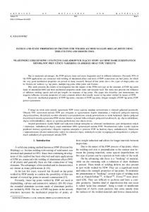
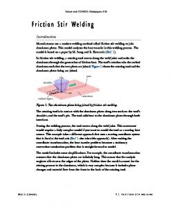
as they are extremely toxic. These health risks are found mainly in fusion welding. However, as the process of FSW is a solid state process, it does not present this kind of risk. This is a topic that worries society, which can mean that in some years important restrictions can be imposed to the most dangerous welding processes. The traditional FSW process consists of the insertion of a rotational tool, formed by a pin and a shoulder, into the abutting surfaces of pieces to be welded and moved along the weld joint, as illustrated in Fig. 1. During the process, the pin located inside the weld joint, generating heat through both friction and plastic deformation softens the material and enables plastic flow, causing the mixture of materials. At the same time, the shoulder placed on the surface of the seam heats and drags material from the front to the back side of the tool, preventing leakage of material out of the welding joint and forming a smooth surface. During the welding process the FSW tool can be tilted backward (travel angle) and sideways (work angle), Fig. 2. While travel angles different from zero are mainly applied when a rotational shoulder tool is used, work angles different from zero are applied in dissimilar-thickness butt weld applications. This process is applied mainly to butt, lap and T-butt weld joints but other joint geometries can be welded.
2. Machine characteristics and applications
⁎ Corresponding author. E-mail addresses:
[email protected] (N. Mendes),
[email protected] (P. Neto),
[email protected] (A. Loureiro),
[email protected] (A.P. Moreira).
http://dx.doi.org/10.1016/j.matdes.2015.10.124 0264-1275/© 2015 Elsevier Ltd. All rights reserved.
Machines used in FSW present different characteristics which concerns to its physical configuration. Depending on the application (welding joint), the equipment that displays the most suitable characteristics must be chosen according to different technical capabilities:
N. Mendes et al. / Materials and Design 90 (2016) 256–265
257
Table 1 Relevant loads for the FSW process. Axial force (Fz) Axial force is one of the main process parameters. It is responsible for the friction between the FSW tool and the work pieces, contributing to heat generation in the FSW process. Furthermore, axial force is responsible for applying forging pressure which is vital to obtain good weld formation; Traverse force Traverse force is responsible for supporting material resistance (Fx) to the tool movement along the joint line; Side force (Fy) The side force arises due to the asymmetry of the FSW process, caused by the direction of tool rotation. The advancing side of the weld is warmer than the retreating side of the weld [2], consequently, the material on the advancing side is softer and less resistant. This force has the direction from the retreating side to the advancing side of the weld; Torque (Mz) Torque is also responsible for friction between the FSW tool and the work pieces. This friction is one of the main heating sources for the process of FSW.
2.3. Sensing capability Fig. 1. Schematic representation of the FSW process.
force, stiffness, accuracy, sensing, decision-making, and flexibility. These capabilities will be analysed in detail in the following sections. 2.1. Force capability A challenging issue in FSW is to have a machine able to support the high loads generated during the welding process, which depends greatly on the type of material and thickness of the work pieces. The most relevant loads acting on a machine during the FSW process are the axial force (Fz), the traverse force (Fx), the side force (Fy), and the torque (Mz), Table 1. The directions of these loads are displayed in Fig. 1. All of these loads play an important role in the process. They are a prerequisite to choose or develop FSW equipment. They also play an important role in the control the FSW process, for example maintaining a given axial force or torque allows conferring a good quality to welded seams. Table 2 shows the axial force requirements for various materials with various thicknesses. 2.2. Stiffness and accuracy capability This is the ability of a FSW equipment withstands loads without undergoing deformation or deflexion. When a FSW machine presents low stiffness its FSW tool deviates from the desired welding path, strongly affecting weld quality. Moreover, low stiff machines tend to cause excessive vibration which in turn can lead to FSW process instability. In general FSW machines present high levels of accuracy however, if machines have low stiffness, their accuracy is reduced due to the same reasons pointed out in the Section 2.2.
Sensing consists on the machine ability to be aware of some phenomena that are occurring in the weld joint, i.e. states and values of direct and indirect welding variables involved in FSW process that reflect the evolution of the welding material and consequent welding formation. In this review, it is considered as direct welding variables the welding parameters that somehow can be actuated in a direct way. Some of the welding parameters that compose the direct variables are the rotational and traverse speeds, the tilt angle and the external heat input. On the other hand, it is considered as indirect variables all those variables that cannot be actuated in a direct way, they depend on other variables. This group of variables is composed by the loads involved in the welding process (axial force, traverse force, side force and torque), the temperature reached in the welding area, the stirred material flow and the stirred material mixture, between others. 2.4. Decision-making capability Control methods can be implemented in the control system of the equipment in order to allow process self-adaptation. The data provided from sensors (values of the direct and indirect variables) are used as feedback to the control system. Therefore, indirect monitored variables converge to desired states and values in which FSW process provides good quality weld. 2.5. Flexibility capability The flexibility of a machine limits the complexity of a welding path (linear, curve) that can be performed. The number of axes (degrees of freedom — DOF) that a machine possesses usually establishes the
Fig. 2. Tilt angles used in the FSW process: (a) travel angle, (b) work angle.
258
N. Mendes et al. / Materials and Design 90 (2016) 256–265
Table 2 Parameters for FSW for different materials: thickness vs. axial force. Material AISI 409 M AA2195-T6 AA6061-T6 AA7075-T6 ADC12 C11000 Cu-DHP R240 AZ31B AZ61A High nitrogen austenitic steel AA6082-T6/ AA7075-T6 AA5083-H111/ Cu-DHP R240 Cu/cuZn30 Al-4.5%Cu-10%TiC AA2124-SiC AA6061/0–10 wt.% ZrB2 AA7005/10 vol.% Al2O3 particles AA6061-T6/AlNp ABS
Thickness (mm)
Axial force (kN)
Reference
4 6.35 6.35 5 4 3.1 1 6 6 2.4
24 13.8 12.5 8 6.9 7 7 3 5 20
[3] [4] [4] [5] [6] [7] [8] [9] [10] [11]
8
12
[12]
1
7
[13,14]
5.5 6 8.5 6 12 3–7 2
[15] [16] [17] [18] [19] [20] [21,22]
3 5 15 6 7 6 6
flexibility of the machine. A one-dimensional (1D) welding path is the least complex requiring the least flexibility (smaller number of axes). The simplest version of this machine possesses just two axes. On the other hand, a two-dimensional (2D) welding path requires more flexibility, not only to move the FSW tool through the two directions but also to maintain work and travel angles. A three-dimensional (3D) welding path is the most demanding in flexibility, a machine to perform the simplest 3D path must have at least five axes. In addition, in many applications multiple welds with multiple directions and with multiple orientations are required, which demands the required flexibility of the machine.
2.6. Applications The choice for a specific FSW machine is dependent on different parameters as indicated above. A major problem is related with the industrialization of the process in general and the capacity of a given FSW machine to produce welds in different parts. Such parts can vary in material, size, geometry, required accuracy, etc. In addition, FSW has been used to produce welds in difficult to weld aluminium alloys and dissimilar materials. Buffa et al. report an experimental campaign to obtain T and lap joints for parts with dimensions of industrial interest (panels 300 × 200 × 3 mm) made of two different aluminium alloys (AA2024–AA7175) [23]. This technologic process is already been used in a wide range of industries, namely aeronautics, aerospace [24], shipbuilding [25], railway, automotive [26], construction, electric, electronic, among others [27,28]. In aeronautics and aerospace industry several parts of aircrafts, rockets and space probes have been manufactured by FSW. This process is appealing because it introduces reduction of manufacturing costs and weight savings. Joining of skins to spars, ribs, and stringers are typical applications of FSW in these industries. The process is suitable for the manufacturing of the following parts: wings, fuselages, empennages, floor panels, aircraft landing gear doors, cryogenic fuel tanks for space vehicles aviation fuel tanks, among others. Shipbuilding industry makes use of FSW process for an extensive range of applications. The FSW process can therefore be considered for welding the following components: panels for decks, sides, bulkheads and floors, hulls and superstructures, helicopter landing platforms, offshore accommodation, masts and booms, and refrigeration plants. Applications of FSW in the railway industry include the manufacturing of the following components: high speed trains; rolling stock of
railways, underground carriages, trams, railway tankers and goods waggons, container bodies, roof and floor panels. The FSW process is currently being used in manufacturing of several automotive mechanical components. The process is suitable to produce different welds, long, straight or curved welds. The process has been applied to produce the following components: trailer beams, cabins and doors, spoilers, front walls, closed body or curtains, drop side walls, frames, floors, bumpers, chassis, fuel and air containers, engine parts, air suspension systems, drive shafts, engine and chassis cradles. FSW has also been applied in construction industry, namely in the construction of aluminium bridges, facade panels (made from aluminium, copper or titanium), window frames, aluminium pipelines and heat exchangers. Moreover, FSW has expanded in the last few years in other application fields like the electrical (e.g. motor housings), oil and gas (e.g. land and offshore pipelines), and nuclear industry. 3. FSW machines Three kinds of machines are reported in literature as viable to perform FSW. These machines are: - Conventional machine tools such as milling machines [29,30]; - Dedicated FSW machines or custom-built machines [31] - Industrial robots [32–34]. 3.1. Conventional machine tools The process of FSW is similar in terms of principle of operation of the equipment to other technological manufacturing processes such as machining, deburring, grinding and drilling. Basically, all of these processes consist in moving a rotating tool through a work piece, producing dragging of material which constitutes the work piece. Thus, it is plausible to assume that a conventional machine tool, such as a milling machine, can be used to perform FSW [35]. However, the loads generated during the FSW process gain more relevance when this equipment is used. The loads involved in FSW are higher than the loads generated in the milling process [36,37]. For this reason, conventional machine tools have to be strengthened in order to increase their load and stiffness capabilities. Thus, there are potential opportunities to modify existing equipment to perform FSW. The machine modifications can be made on several levels: structural, flexibility, decision-making and sensing [38]. The structural modifications are performed in order to make the equipment more robust (some parts of equipment can be replaced such as ways, guides, rails, motors, spindles, etc.). The flexibility can be increased by the introduction of additional motors that provide additional degrees of freedom to the equipment. Owing to the high loads involved in the FSW process, the majority of the solutions have implemented force control to prevent equipment damage and ensure human safety and to achieve good weld quality. The decision-making of the equipment can still be improved providing movement in more directions at the same time. Besides that, the machine can be equipped with multiple sensors to collect different information which will be used to control the equipment through an embedded control solution. These machines are very popular due to the fact that they are widely used in industry for machining purposes, which is one of the most common technologic processes used in industry. Therefore, the existence of this kind of equipment in industry is guaranteed as well as knowledge to operate it. In FSW the use of modified machine tools is recommended for: - Prototyping and small series production of: - Welding long or small work pieces; - Welding thick or thin work pieces; - Applications where high stiffness is required; - Single- or multi-axis applications.
N. Mendes et al. / Materials and Design 90 (2016) 256–265
259
It must be expected low production performance. An example of a modified milling machine is presented in Fig. 3 [39]. 3.2. Dedicated FSW machines Dedicated FSW machines tend to have the highest load capability, stiffness, accuracy and availability [31]. They can assume different configurations presenting distinct levels of flexibility. In this family of machines are inserted the custom-built machines that are machines developed specifically to satisfy special product requirements, for example parts for decks of ships [26]. A requalification of these machines to other applications is difficult in several cases. Typically, dedicated FSW machines are relatively expensive and their cost increases with increase in flexibility. The use of dedicated FSW machines is recommended for high series production of the same part types as conventional machine tools: -
Welding long or small work pieces; Welding thick or thin work pieces; Applications where high stiffness is required; Single- or multi-axis applications).
Additionally, the use of custom-built machines must be considered for applications where the alternative solution does not exist or is relatively expensive. An example of a dedicated FSW machine is presented in Fig. 4. The welding of high temperature materials, such as steel, stainless steel, titanium, nickel alloys among others, requires high load support which in turn requires highly robust machines. The most recommended equipment to weld these materials is dedicated FSW machine because it is the most robust and structurally stiff machine. There has been an increasing interest in development of portable FSW machines. This kind of equipment would bring a possibility of applying FSW in remote locations as well as in-situ repair and addition of components to large structures. In order to develop portable FSW machines, FSW tools, mechanisms and loads evolved in FSW have been studied [40]. Actually, the main restrictions imposed to portability of
Fig. 4. Dedicated FSW machine — FSW LegioTM.
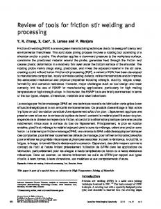
the process are reduction of the loads required to perform FSW and weight of equipment. Although there have been some study about portable FSW, at this time no commercially available systems are known. Popularization of mobile robots that have been assisted in the last few years can aid to develop effective solutions [41]. 3.3. Robotic FSW machines A third family of machines that has recently been introduced in FSW of metals concerns to robotic machines (industrial robots). During several years, low load capability (payload) and low stiffness of industrial robots have prevented the use of robots in FSW applications. However, recent developments have led to development and consequent release in the market of robotic equipment with high payloads which are capable of performing FSW on material of thin-to-moderate thickness. The main advantages presented by robotic machines are flexibility and process automation which allow for significant productivity improvements. As an example, consider a work piece with welds on multiple sides. A robotic solution allows welding on multiple sides of the work piece in a single setup (for instance the work piece shown in Fig. 5). This reduces non-value-added materials handling applications and can yield a lot of improvements in productivity, consequently reducing welding cost. Applications recurring to 3D welding paths have become increasingly attractive and feasible with the use of a robotic system for FSW. A great range of this kind of application just needs an industrial robot with five DOF which becomes the use of industrial robots more appealing since the most common robots in the market possess five or six DOF. The robotic-based solutions are available in two basic categories: - Articulated arm robots [32,33,42]; - Parallel-kinematic robots [43].
Fig. 3. Modified milling machine for FSW (Source: [39]).
Articulated arm robots present high repeatability and flexibility but low accuracy that worsens when they are subjected to high loads. Comparing articulated robots to dedicated FSW machines, generally these
260
N. Mendes et al. / Materials and Design 90 (2016) 256–265
Fig. 5. Robotic FSW of a multi welding part (Source: [44]).
robots display higher flexibility and decision-making capability besides the fact that they are remarkably lower in cost. However, these types of robots have relatively low stiffness and moderate load capability which limit their application. Given their flexibility and relative low cost, they can be the lowest-cost solution by far but have a limited range of materials on which they can perform FSW due to the high loads required to weld some materials. As a general rule, the most robust robots are capable of welding up to 6 (mm) thick aluminium material [42,45,46]. Their capability in higher-melting-point materials tend to be somewhat less. The drawbacks are related to high compliance, which cause process stability issues. The use of articulated arm robots is recommended for: - relatively thin material; - applications having multiple welds that would otherwise require multiple setups; - dissimilar-thickness butt welds (tailor-welded blanks), these kinds of welds require both a travel angle and a work angle (more flexibility is required). Robots are ideal solutions for this application; - applications where multi-axis capability is required (different tool orientations are needed); - higher work volume applications where productivity is an important factor. Marcotte and Abeele [42] have developed a robotic FSW system based on an articulated arm robot. In this study was successfully reported the production of aluminium welds of 1D, 2D and 3D welding paths. Fig. 6 presents an articulated arm robot capable to perform FSW of 1D, 2D and 3D welding paths. The friction stir spot welding (FSSW), a variant process of FSW, have also been reported as feasible and appealing when performed by an articulated arm robot [47]. The other basic robotic configuration is the parallel-kinematic robot. This type of robot support higher loads and have significantly higher stiffness than an articulated arm robot. However, their cost can be notably higher, and their work volume is significantly lesser than the articulated arm robots, as well as the allowed range of orientation. A typical example of this family of robots is the Tricept [19,48], shown in Fig. 7. Parallelkinematic robots should be considered in similar applications to the articulated arm robots with the following particular characteristics:
Fig. 6. Articulated arm robot performing FSW at the University of Coimbra.
FSW of 3D welding paths. Table 3 displays a comparative analysis among the different machines. 4. Robotic systems In general, when an articulated robot is used to produce FSW, robot's paths suffer some positional modifications (errors) which may put at risk the quality of the weld. A solution to overcome this drawback is the tight control of loads acting on the robot during the welding process. Diverse path adjustment techniques have been proposed successfully so far but none of them have solved the problem completely. 4.1. Limitations of articulated arm robots
- The work volume of the work pieces is relatively small; - The work piece can be welded near or close to the horizontal plane; - The load or stiffness requirements are somewhat higher.
Owing to the high loads involved in the FSW process and low stiffness presented by articulated arm robots, they cannot guarantee the same robustness as either a conventional machine tool or a dedicated FSW machine [28]. Articulated arm robots are composed by joints and links that have associated servomotors, gearboxes and transmission axes. All of these elements are subjugated to non-predictable phenomena such as backlash, vibration, bearing run-out, between others that attribute compliance1 to articulated arm robots leading to deflexions in the robot's joints and links [50,51]. Thus, encoders mounted to robots' linkage motors to read their position cannot detect such deflexions. The encoder readings are then fed back to the robots control system determining erroneously the position of their end-effectors (i.e. FSW tool).
Welding of small thinness high temperature materials is also possible with this kind of robot. Shi et al. [49] have developed a 3-PRS (Prismatic, Revolute and Spherical joint) parallel mechanism to perform
1 A robot is said compliant when it is not completely rigid and when it can sense and control the forces it applies to work pieces.
N. Mendes et al. / Materials and Design 90 (2016) 256–265
261
used. At the same time, if the welds could be performed at lower loads, machine load requirements will also be lower. When load control is employed, excessive loads and loss of contact between FSW tool and work pieces are prevented. As a result, the damage of the components involved in the process (FSW tool, machine, work pieces, etc.) and formation of welding defects are avoided and worker safety is guaranteed.
4.3. Welding parameters affecting stiffness machine requirements
Fig. 7. Parallel-kinematic robot (Tricept) performing FSW.
While robots are moving in the free air, these deflexions are negligible small as pre-known loads and mass can be account for, but when the tool comes in contact with work pieces all these joints and links cause deviations between the predefined robot path and the actual followed path. This leads to deviations away from the welding joint affecting negatively weld quality. 4.2. Improving robotic FSW accuracy In order to enable articulated arm robots, which present low stiffness, to perform FSW it has been proposed in several studies [33,34, 52–54] to control the loads involved in the process instead of to control the robot's position. In this way it is possible to obtain the same weld quality using an articulated arm robot as when a stiff FSW machine is
As pointed out above, welding parameters affect resulting weld quality and formation of defects. Moreover, each individual parameter also affects each other, allowing welds of similar quality in the presence of different sets of parameters to be achieved [55]. It is demonstrated in literature reporting FSW of thermoplastics as well as metals that the amount of heat provided to a welding joint is a key point to achieve quality welds. Such amount of heat depends on a number of parameters such as: rotational speed, traverse speed, axial force, torque, plunge depth, external heating provided to the joint, type of material, thickness of the work pieces, etc. Taking into account the exposed above, it is possible to reduce loads generated in the welding process as well as the required level of machine stiffness by keeping the same amount of heat dissipated in the joint. This is achieved by changing the other welding parameters such as rotational speed, traverse speed, etc. [21,22]. Welds performed in a milling machine controlled in motion control have shown a significant reduction of axial force when the rotational speed is increased [36]. This is a result of the increased heat input, which causes the material to soften more. This important conclusion suggests that the deflections in the robot can be significantly reduced by welding at higher rotational speed and at a lower axial force. However, the friction coefficient between tool and material is a limiting factor for the rotational speed. There will not be a proper material flow if a certain rotational speed is not reached, which can cause welding defects. Within a certain parameter range, the reaction forces can be reduced through proper setting of the process parameters, including tool design to make it possible to apply robots for FSW. Cook et al. [53] used a milling machine to perform FSW on aluminium concluding that the heat input generated by the axial force, rotational speed and traverse speed together with the tool design, must be selected in a proper way. Too high heat input and axial force together with too low traverse speed will simply cause the tool to melt down into the material. On the other hand, a high heat input will produce a softer material during the FSW process, which is beneficial for the robot performance and accuracy. This study summarizes as the axial force requirements imposed to the robot can be reduced by operating at high tool rotational speed and low traverse speed. Crawford et al. [56] have shown by simulation of the robotic FSW process that axial force and torque decrease as rotational speed is increased. The FSW plunging stage was studied by Zimmer et al. [57] concluding that it is feasible to decrease axial force and torque by increasing generated energy (higher rotational speed and lower plunging speed) and/or using control force instead motion control. Similar conclusions were obtained by Mendes et al. [21,22] for the FSW welding stage.
Table 3 FSW equipment features. Characteristics ↓
Equipment Milling machine
FSW machine
Parallel robot
Articulated robot
Flexibility Cost Stiffness Work volume Setup time Number of programming options Capacity to produce complex welds Control type
Low Medium High Medium Low Low Low Motion
Low/medium High High Medium High Medium Medium Motion/force
High High High Low Medium High High Motion
High Low Low High Medium High High Motion
262
N. Mendes et al. / Materials and Design 90 (2016) 256–265
4.4. Sensing methods to improve weld quality In FSW of metallic materials the robotization of the process and the use of force/motion control have encouraged a number of studies to achieve improved weld quality. A good example is the study presented by Fleming et al. [58] that investigated automatic fault detection in robotic friction stir lap welds. In order to overcome faults as worm-holes (voids in the weld), real-time analysis of axial force though a methodology based on principal component analysis (PCA) were proposed. A similar study was presented by Yang et al. [59] who have proposed a real-time monitoring algorithm to detect gaps in friction stir butt welding. Side FSW tool deviation has been an issue that has been studied in robotic FSW of aluminium. In order to prevent excessive side deviation from joint line, several studies have been carried out [44,60–62]. A method for automatic seam-tracking in FSW of lap joints is presented by Fleming et al. [60]. In this method, tracking is accomplished by weaving the FSW tool back-and-forth perpendicular to the traverse direction and monitoring force and torque signals. This approach showed to be efficient and weaving does not reduce weld quality. It can be utilized in robotic and non-robotic FSW process. The same method has been studied for FSW of T-joints by Fleming et al. [61]. The feasibility of the method was shown as well as the improvement of weld quality. Backer et al. [44,62] demonstrated that side deviations are caused by robot deflexion. Compensation of these side deviations are pointed out as irrelevant during welding of thin and/or soft materials but are necessary for butt-joint welding of high-strength aluminium alloys. Online sensing through vision and laser sensors were used to measure robot deviations. Three different approaches proved to be efficient: - Using a seam-tracking system based on vision; - Implementing compensations in the pre-programmed robot paths (off-line); - Using pre-heating techniques of welding joints. 5. Control of robotic system Over the last years, robot force control has assumed an increasingly important role in the performance of some robotic tasks. It is not only used in tasks where it is sufficient to maintain the contact forces and torques within certain limits but also on tasks where the deflexion of the robot is a major factor. The first case is the most common in robotic applications such as deburring, polishing and assembly. In the second case, applications such as milling, grinding, drilling and FSW are typical examples where stiffness and payload come into play. Even though these two cases can seem different, the approach to deal with them is always the same, i.e. controlling force and torque of interaction between robot end-effector and environment in an appropriate way. Depending on the robotic task, a control technique should be chosen such as: 1) Passive force control when the contact forces should be controlled to achieve task success, but it is sufficient to keep them inside some safety domain giving to the end-effector some freedom to adapt to environment [63]; 2) Active force control when the contact forces should be carefully controlled because they contribute directly to the success of the task [63–72]. In the first case, contact forces produce an undesirable effect on the task. They are not necessary for the process to be carried out. In the second case, the contact forces are necessary to finish the task correctly, i.e., the contact forces should be controlled, making them assume some particular value or to follow a force profile. Active force control is the most used in industrial applications. Although it requires higher investment, both monetary and information processing, it can guarantee that high contact forces will never occur. In order to afford disturbance rejection capability, several studies have
been carried out. From the more common methods presented in literature: motion control, force control and hybrid force/motion control, one that has been pointed out by the scientific community as one of the most suitable to deal with robot deflexion and force/torque feedback is the hybrid force/motion control [63]. This method allows controlling the non-constrained task directions in motion control and the constrained task directions in force control. Hybrid force/motion control architecture consists of an external force control loop closed around an internal motion control loop. In order to deal with robot deflexion this approach is the most suitable because the force controller is designed so as to dominate the motion controller. Hence, a position error is tolerated along the constrained task directions in order to ensure force regulation. Figs. 8 and 9 illustrate two different versions of this controller. Up to now, many different kinds of robotic systems using force control strategies have been developed and successfully applied to various industrial processes such as polishing [64] and deburring [65, 66]. A large number of force control techniques (fuzzy, PI, PID, etc.) with varying complexity have been proposed thus far [67,68,70,71,73, 74]. Pires et al. present a fuzzy-PI controller suitable to deal with high noisy robotic environments [67]. Shih-Tin and Ang-Kiong introduced an hierarchical fuzzy force control system for robot contact motion [68]. An analytical fizzy-PID controller with constant self-tuned control gain is proposed by Tang and Kwong [70]. A fuzzy logic control system that allow an industrial robot to improve highly its accuracy is described by Kwang and Louis [71]. An hybrid force/motion control system based on fuzzy-PI is introduced by Mendes et al. [73]. According to the current state of the art, there are four different ways to control the robotic FSW process (they will be discussed in the following sections): - Adjusting the plunge depth according to a given set force [33,34,36, 43,52,75]; - Adjusting the plunge depth according to a given set torque for the robot motors [32]; - Adjusting the plunge depth according to a given set torque for the tool [29]; - Adjusting the traverse speed according to a given set force [30,39]. 5.1. Adjusting the plunge depth according to a given set force This approach proposes the use of force control where the plunge depth (penetration of the FSW tool along axial direction (z-axis)) is adjusted as the tool traverses along the welding joint. Thus, axial force (Fz) converges to a set force ensuring proper forging and consolidation of stirred material. In order to implement this system, a force sensor to collect force readings about loads acting in the FSW tool is needed. These force readings are fed back into a control system that in turn controls robot servomotors attributing proper position to the FSW tool. This control architecture is called direct force control, shown in Fig. 8, where fd is the set force and fe is the measured force. A force sensor is relatively easy to integrate but can be expensive and susceptive to noise disturbance. An alternative way to use a force sensor was studied by Gibson et al. [76] who present a low-cost force measurement system that exploits the robotic link deflexion for force measurement purposes. The axial force has been the most used control parameter because it is the highest load acting on the FSW tool. Therefore, preventing axial
Fig. 8. Direct force control for a FSW robotic system.
N. Mendes et al. / Materials and Design 90 (2016) 256–265
263
increase and may reach too high values that may endanger the integrity on the equipment involved in the FSW process. When a force control approach is employed (similar to torque control) excessive tool penetration can occur. However, excessive values of axial force will be avoided by the control system. 5.4. Adjusting the traverse speed according to a given set force
Fig. 9. Indirect force control for a FSW robotic system.
force to reach extremely high values, all the hardware system and the FSW process itself are safe. 5.2. Adjusting the plunge depth according to a given set torque for the robot motors This second approach is closely similar to the first one, just differing in raw data. In this case the data consists of readings of robot motors torques that are processed to estimate loads acting on the FSW tool. Recurring to the robot Jacobian matrix (J), the applied axial force can be calculated based upon the measured current supplied to each motor in a serially configured articulating arm robot. This control architecture is shown in Fig. 9. The major advantage of this solution is the elimination of expensive force sensors, reducing implementation costs. This solution, called indirect force control, just allow to achieve a rough control of the contact force due to the compliance nature of the articulated robot, only an approximated model of the robot and stiffness is possible to formulate [63,77]. Smith [32] has been quite successful in performing FSW on aluminium using an articulated arm robot with embedded indirect force control, however, the update time was limited to 2 (Hz) because of the computational burden of computing the manipulator Jacobian.
This approach consists of force control using traverse speed as the actuating variable. Therefore, it is similar to the approach presented in Section 5.1 but in this case a force sensor is used to collect force readings about loads acting in the FSW tool. This approach was proposed by Longhurst et al. [30,39] in the automation of a milling machine to perform FSW along one of its actuation axes (one motor), i.e. welding direction is aligned with one of the axes of the milling machine. It was reported that this system is more robust and stable when compared with a force controller that uses plunge depth as the actuating variable. However, when the traverse speed is used as actuating variable, the plunge depth must be kept constant (not change relative to the position of the work piece surface). This kind of approach is difficult to apply to articulated robots due to its compliance nature. For instance, if a six axis articulated arm robot is used to control axial force via traverse speed, more than one linkage must be adjusted simultaneously as the tool continuously traverses along the welding joint. Any simultaneous multi-linkage adjustment possibly could result in small fluctuations in the plunge depth of the tool. This will further lead to fluctuations in the axial force and possibly negating the advantages of using traverse speed as the controlling variable. This solution has associated the same investment costs as force control via plunge depth. 6. Conclusion and future trends
5.3. Adjusting the plunge depth according to a given set torque for the robot motors This approach takes into account the torque exercised on the tool to feed back the robot control system. Axial displacements are sent to the robot arm to change the previous programmed robot welding path in order to reach a set torque. It is referred in literature [29] that the control of the torque provides more stable results than the control of the axial force when the actuating variable is the plunge depth. In fact, the torque is a more representative variable of the loads acting in the FSW tool than the axial force. The control method is based upon the mathematical model of welding torque given by: Z Torque ¼
R e
Z 2πr 2 σdr þ 2πr2 tσ þ
r 0
2πr 2 σdr
ð1Þ
Where σ is the shear flow stress (N/m2) at the shear interface boundary, i.e. tool surface, R is the radius of tool shoulder (m), r is the radius of tool pin (m), and t is the length of tool pin (m). The model predicts that welding torque is a function of plunge depth. The major benefits of torque control in relation to force control are simplicity and lower cost. A procedure to collect torque readings is recurring to a force/torque sensor. An alternative economical way to collect torque data can simply be using indirect measuring via the supplied current to the spindle motor or in the case of a hydraulic motor, the pressure difference across the motor. Torque control has been successfully demonstrated for the automation of a conventional milling machine. No similar study was found to articulated robots. Further research is needed to assess feasibility of this solution. Torque control may not be an attractive control procedure to FSW of thermoplastics because this process is very susceptible to concentrate excessive energy (reaching high temperatures and even melting of material) in some stages of the welding joint promoting excessive tool penetration on these stages. In this situation, the axial force tends to
The common machines used in FSW, i.e. conventional machine tools, dedicated FSW machines and industrial robots, present distinctive characteristics which determine their suitability to each application (requirements imposed by the parts to be manufactured). The use of industrial robots in the process of FSW makes it a more attractive welding process, opening the door for its expansion in manufacturing industry. By controlling the loads involved in the FSW process it is feasible to obtain quality welds with an articulated arm robot. There has been a research axis that intends to make industrial robots more autonomous, flexible, easy-to-use and capable to make decisions. This can extend the use of industrial robots to non-robotic experts for robotic FSW tasks. An autonomous robot will have incorporated more sensors and artificial intelligence that will allow the robot to cope with positional differences (errors) and keep the FSW process controlled as well as all the welding variables stabilized during whole process. Industrial robots have great potential in the FSW of soft metals and polymers in the short time being expectable that this one will be the most used machine in the welding of soft metals. Nevertheless, for FSW of metals with a relatively high thickness the loads involved preclude the use of robots as machine tool. The evolution of FSW has been enormous in the last years. Current research trends focus on the exploration of new welding materials such as dissimilar materials or composites. Other important point is the manufacturing of dissimilar thickness welding joints which is of great interest and is poorly studied as well as welding joints of 3D welding trajectory and of complex geometry. The FSW machines and its capabilities mentioned in this paper (force, stiffness, accuracy, sensing, decision-making and flexibility) will have a relevant role in the advance of these techniques in a near future. In addition, the FSW machines are the base for the evolution of FSW related processes like Friction Stir Spot Welding (FSSW), Friction Stir Processing (FSP) and Friction Stir Channelling (FSC), and the appearance of new applications for FSW.
264
N. Mendes et al. / Materials and Design 90 (2016) 256–265
Acknowledgements This research was supported by FEDER funds through the programme COMPETE (Programa Operacional Factores de Competitividade), under the project CENTRO-07-0224-FEDER-002001(MT4MOBI) and by national funds through FCT (Fundação para a Ciência e a Tecnologia) under the project PEst-C/EME/UI0285/2013. References [1] Thomas W, Nicholas E, Needham J, Murch M, Temple-Smith P, Dawes C. Friction-stir butt welding. International patent application no. PCT/GB92/02203, 1991. [2] H.W. Zhang, Z. Zhang, J.T. Chen, The finite element simulation of the friction stir welding process, Mater. Sci. Eng. A 403 (2005) 340–348, http://dx.doi.org/10. 1016/j.msea.2005.05.052. [3] A.K. Lakshminarayanan, V. Balasubramanian, Assessment of sensitization resistance of AISI 409 M grade ferritic stainless steel joints using modified Strauss test, Mater. Des. 39 (2012) 175–185, http://dx.doi.org/10.1016/j.matdes.2012.02.038. [4] M. Melendez, W. Tang, C. Schmidt, M.C. JC, A.C. Nunes, L.E. Murr, Tool forces developed during friction stir welding, BiblioGov, 2013. [5] S. Rajakumar, C. Muralidharan, V. Balasubramanian, Influence of friction stir welding process and tool parameters on strength properties of AA7075-T6 aluminium alloy joints, Mater. Des. 32 (2011) 535–549, http://dx.doi.org/10.1016/j.matdes.2010.08.025. [6] Y.G. Kim, H. Fujii, T. Tsumura, T. Komazaki, K. Nakata, Three defect types in friction stir welding of aluminum die casting alloy, Mater. Sci. Eng. A 415 (2006) 250–254, http://dx.doi.org/10.1016/j.msea.2005.09.072. [7] Y.M. Hwang, P.L. Fan, C.H. Lin, Experimental study on friction stir welding of copper metals, J. Mater. Process. Technol. 210 (2010) 1667–1672, http://dx.doi.org/10. 1016/j.jmatprotec.2010.05.019. [8] R.M. Leal, N. Sakharova, P. Vilaça, D.M. Rodrigues, A. Loureiro, Effect of shoulder cavity and welding parameters on friction stir welding of thin copper sheets, Sci. Technol. Weld. Join. 16 (2011) 146–152, http://dx.doi.org/10.1179/1362171810Y. 0000000005. [9] G. Padmanaban, V. Balasubramanian, An experimental investigation on friction stir welding of AZ31B magnesium alloy, Int. J. Adv. Manuf. Technol. 49 (2009) 111–121, http://dx.doi.org/10.1007/s00170-009-2368-1. [10] A. Razal Rose, K. Manisekar, V. Balasubramanian, Effect of axial force on microstructure and tensile properties of friction stir welded AZ61A magnesium alloy, Trans. Nonferrous Met. Soc. China 21 (2011) 974–984, http://dx.doi.org/10.1016/S10036326(11)60809-1. [11] H.B. Li, Z.H. Jiang, H. Feng, S.C. Zhang, L. Li, P.D. Han, et al., Microstructure, mechanical and corrosion properties of friction stir welded high nitrogen nickel-free austenitic stainless steel, Mater. Des. 84 (2015) 291–299, http://dx.doi.org/10.1016/j. matdes.2015.06.103. [12] A.H. Jamshidi, Influences of pin profile on the mechanical and microstructural behaviors in dissimilar friction stir welded AA6082–AA7075 butt joint, Mater. Des. 67 (2015) 413–421, http://dx.doi.org/10.1016/j.matdes.2014.11.055. [13] I. Galvão, R.M. Leal, A. Loureiro, D.M. Rodrigues, Material flow in heterogeneous friction stir welding of aluminium and copper thin sheets, Sci. Technol. Weld. Join. 15 (2010) 654–660, http://dx.doi.org/10.1179/136217110X12785889550109. [14] I. Galvão, C. Leitão, A. Loureiro, D.M. Rodrigues, Study of the welding conditions during similar and dissimilar aluminium and copper welding based on torque sensitivity analysis, Mater. Des. 42 (2012) 259–264, http://dx.doi.org/10.1016/j.matdes. 2012.05.058. [15] C. Meran, V. Kovan, Microstructures and mechanical properties of friction stir welded dissimilar copper/brass joints, Mater. Werkst. 39 (2008) 521–530, http:// dx.doi.org/10.1002/mawe.200800278. [16] A. Kumar, M.M. Mahapatra, P.K. Jha, N.R. Mandal, V. Devuri, Influence of tool geometries and process variables on friction stir butt welding of Al–4.5%Cu/TiC in situ metal matrix composites, Mater. Des. 59 (2014) 406–414, http://dx.doi.org/10. 1016/j.matdes.2014.02.063. [17] F. Cioffi, R. Fernández, D. Gesto, P. Rey, D. Verdera, G. González-Doncel, Friction stir welding of thick plates of aluminum alloy matrix composite with a high volume fraction of ceramic reinforcement, Compos. A: Appl. Sci. Manuf. 54 (2013) 117–123, http://dx.doi.org/10.1016/j.compositesa.2013.07.011. [18] I. Dinaharan, N. Murugan, Influence of friction stir welding parameters on sliding wear behavior of AA6061/0–10 wt.% ZrB2 in-situ composite butt joints, J. Miner. Mater. Charact. Eng. 10 (2011) 1359–1377, http://dx.doi.org/10.4236/jmmce.2011. 1014107. [19] L. Ceschini, I. Boromei, G. Minak, A. Morri, F. Tarterini, Effect of friction stir welding on microstructure, tensile and fatigue properties of the AA7005/10vol.%Al2O3p composite, Compos. Sci. Technol. 67 (2007) 605–615, http://dx.doi.org/10.1016/j. compscitech.2006.07.029. [20] B. Ashok Kumar, N. Murugan, Optimization of friction stir welding process parameters to maximize tensile strength of stir cast AA6061-T6/AlNp composite, Mater. Des. 57 (2014) 383–393, http://dx.doi.org/10.1016/j.matdes.2013.12.065. [21] N. Mendes, A. Loureiro, C. Martins, P. Neto, J.N. Pires, Effect of friction stir welding parameters on morphology and strength of acrylonitrile butadiene styrene plate welds, Mater. Des. 58 (2014) 457–464, http://dx.doi.org/10.1016/j.matdes.2014. 02.036. [22] N. Mendes, A. Loureiro, C. Martins, P. Neto, J.N. Pires, Morphology and strength of acrylonitrile butadiene styrene welds performed by robotic friction stir welding, Mater. Des. 64 (2014) 81–90, http://dx.doi.org/10.1016/j.matdes.2014.07.047.
[23] G. Buffa, L. Fratini, V. Ruisi, Friction stir welding of tailored joints for industrial applications, Int. J. Mater. Form. 2 (2009) 311–314, http://dx.doi.org/10.1007/s12289009-0579-5. [24] O.S. Salih, H. Ou, W. Sun, D.G. McCartney, A review of friction stir welding of aluminium matrix composites, Mater. Des. 86 (2015) 61–71, http://dx.doi.org/10.1016/j. matdes.2015.07.071. [25] R. Johnson, P.L. Threadgill, Progress in friction stir welding of aluminium and steel for marine applications, Adv. Mar. Mater. Appl. (2003)http://dx.doi.org/10.3940/ rina.amm.2003.3. [26] C.B. Smith, W. Crusan, J.R. Hootman, J.F. Hinrichs, R.J. Heideman, J.S. Noruk, Friction stir welding in the automotive industry, TMS Annu. Meet. Automot. Alloy. Join. Alum. Symp. (Aluminum 2001), 2001 2001, pp. 175–185. [27] S. Shah, S. Tosunoglu, Friction stir welding: current state of the art and future prospects, 16th World Multi-Conference Syst. Cybern. Informatics, Miami, Florida 2012, pp. 1–6. [28] B.T. Gibson, D.H. Lammlein, T.J. Prater, W.R. Longhurst, C.D. Cox, M.C. Ballun, et al., Friction stir welding: process, automation, and control, J. Manuf. Process. 16 (2014) 56–73, http://dx.doi.org/10.1016/j.jmapro.2013.04.002. [29] W.R. Longhurst, A.M. Strauss, G.E. Cook, P.A. Fleming, Torque control of friction stir welding for manufacturing and automation, Int. J. Adv. Manuf. Technol. 51 (2010) 905–913, http://dx.doi.org/10.1007/s00170-010-2678-3. [30] W.R. Longhurst, A.M. Strauss, G.E. Cook, Enabling automation of friction stir welding: the modulation of weld seam input energy by traverse speed force control, J. Dyn. Syst. Meas. Control. 132 (2010) 041002, http://dx.doi.org/10.1115/1. 4001795. [31] Y. Okawa, M. Taniguchi, H. Sugii, Y. Marutani, Development of 5-axis friction stir welding system, SICE-ICASE Int. Jt. Conf., IEEE; 2006 2006, pp. 1266–1269, http:// dx.doi.org/10.1109/SICE.2006.315435. [32] C.B. Smith, Robotic friction stir welding using a standard industrial robot, 2nd Frict. Stir Weld. Int. Symp., Gothenburg, Sweden, 2000. [33] M. Soron, I. Kalaykov, A robot prototype for friction stir welding, 2006 IEEE Conf. Robot. Autom. Mechatronics, IEEE 2006, pp. 1–5, http://dx.doi.org/10.1109/ RAMECH.2006.252646. [34] N. Mendes, P. Neto, M.A. Simão, A. Loureiro, J.N. Pires, A novel friction stir welding robotic platform: welding polymeric materials, Int. J. Adv. Manuf. Technol. (2014)http://dx.doi.org/10.1007/s00170-014-6024-z. [35] T. Minton, D.J. Mynors, Utilisation of engineering workshop equipment for friction stir welding, J. Mater. Process. Technol. 177 (2006) 336–339, http://dx.doi.org/10. 1016/j.jmatprotec.2006.03.227. [36] W.R. Longhurst, A.M. Strauss, G.E. Cook, C.D. Cox, C.E. Hendricks, B.T. Gibson, et al., Investigation of force-controlled friction stir welding for manufacturing and automation, Proc. Inst. Mech. Eng. B J. Eng. Manuf. 224 (2010) 937–949, http://dx.doi. org/10.1243/09544054JEM1709. [37] B.J. De, Robotic Friction Stir Welding for Flexible Production, Lund University, 2012. [38] H. Yavuz, Function-oriented design of a friction stir welding robot, J. Intell. Manuf. 15 (2004) 761–775, http://dx.doi.org/10.1023/B:JIMS.0000042662.79454.c5. [39] W.R. Longhurst, Force Control of Friction Stir Welding, Vanderbilt University, 2009. [40] R.J. Steel, S.M. Packer, R.D. Fleck, S. Sanderson, C. Tucker, Proceedings of the 1st International Joint Symposium on Joining and Welding, Proc. 1st Int. Jt. Symp. Join. Weld. Elsevier 2013, pp. 125–127, http://dx.doi.org/10.1533/978–1-78242164-1.125. [41] N. Ku, S. Ha, M.-I. Roh, Design of controller for mobile robot in welding process of shipbuilding engineering, J. Comput. Des. Eng. 1 (2014) 243–255, http://dx.doi. org/10.7315/JCDE.2014.024. [42] O. Marcotte, L. Vanden-Abeele, 2d and 3d friction stir welding with articulated robot arm, 8th Int. Symp. Frict. Stir Weld. 2010 2010, pp. 778–797. [43] X. Zhao, P. Kalya, R.G. Landers, K. Krishnamurthy, Design and implementation of a nonlinear axial force controller for friction stir welding processes, 2007 Am. Control conf., IEEE 2007, pp. 5553–5558, http://dx.doi.org/10.1109/ACC.2007.4282731. [44] J. De Backer, A.-K. Christiansson, J. Oqueka, G. Bolmsjö, Investigation of path compensation methods for robotic friction stir welding, Ind. Robot Int. J. 39 (2012) 601–608, http://dx.doi.org/10.1108/01439911211268813. [45] E.F. Shultz, A. Fehrenbacher, F.E. Pfefferkorn, M.R. Zinn, N.J. Ferrier, Shared control of robotic friction stir welding in the presence of imperfect joint fit-up, J. Manuf. Process. 15 (2013) 25–33, http://dx.doi.org/10.1016/j.jmapro.2012.07.002. [46] P. Wanjara, B. Monsarrat, S. Larose, Gap tolerance allowance and robotic operational window for friction stir butt welding of AA6061, J. Mater. Process. Technol. 213 (2013) 631–640, http://dx.doi.org/10.1016/j.jmatprotec.2012.10.010. [47] J.F. Hinrichs, C.B. Smith, B.F. Orsini, R.J. DeGeorge, B.J. Smale, P.C. Ruehl, Friction stir welding for the 21st century automotive industry, Fifth Int. Conf. Frict. Stir Weld., Metz, TWI, France 2004, pp. 1–13. [48] L.M. Marzoli, A.V. Strombeck, J.F. Dos Santos, C. Gambaro, L.M. Volpone, Friction stir welding of an AA6061/Al2O3/20p reinforced alloy, Compos. Sci. Technol. 66 (2006) 363–371, http://dx.doi.org/10.1016/j.compscitech.2005.04.048. [49] J. Shi, Y. Wang, G. Zhang, H. Ding, Optimal design of 3-DOF PKM module for friction stir welding, Int. J. Adv. Manuf. Technol. 66 (2012) 1879–1889, http://dx.doi.org/10. 1007/s00170-012-4467-7. [50] U. Schneider, M. Drust, M. Ansaloni, C. Lehmann, M. Pellicciari, F. Leali, et al., Improving robotic machining accuracy through experimental error investigation and modular compensation, Int. J. Adv. Manuf. Technol. (2014)http://dx.doi.org/10.1007/ s00170-014-6021-2. [51] F. Leali, A. Vergnano, F. Pini, M. Pellicciari, G. Berselli, A workcell calibration method for enhancing accuracy in robot machining of aerospace parts, Int. J. Adv. Manuf. Technol. (2014)http://dx.doi.org/10.1007/s00170-014-6025-y. [52] C.B. Smith, J.F. Hinrichs, W.A. Crusan, Robotic friction stir welding: the state-of-theart, 4th Frict. Stir Weld. Int. Symp., CD-ROM, 2003.
N. Mendes et al. / Materials and Design 90 (2016) 256–265 [53] G.E. Cook, R. Crawford, D.E. Clark, A.M. Strauss, Robotic friction stir welding, Ind. Robot Int. J. 31 (2004) 55–63, http://dx.doi.org/10.1108/01439910410512000. [54] A. Bres, B. Monsarrat, L. Dubourg, L. Birglen, C. Perron, M. Jahazi, et al., Simulation of friction stir welding using industrial robots, Ind. Robot Int. J. 37 (2010) 36–50, http://dx.doi.org/10.1108/01439911011009948. [55] L. Shi, C.S. Wu, H.J. Liu, The effect of the welding parameters and tool size on the thermal process and tool torque in reverse dual-rotation friction stir welding, Int. J. Mach. Tools Manuf. 91 (2015) 1–11, http://dx.doi.org/10.1016/j.ijmachtools. 2015.01.004. [56] R. Crawford, G.E. Cook, A.M. Strauss, D.A. Hartman, Modelling of friction stir welding for robotic implementation, Int. J. Model. Identif. Control. 1 (2006) 101–106. [57] S. Zimmer, L. Langlois, J. Laye, R. Bigot, Experimental investigation of the influence of the FSW plunge processing parameters on the maximum generated force and torque, Int. J. Adv. Manuf. Technol. 47 (2010) 201–215, http://dx.doi.org/10.1007/ s00170-009-2188-3. [58] P. Fleming, D. Lammlein, D. Wilkes, K. Fleming, T. Bloodworth, G. Cook, et al., Inprocess gap detection in friction stir welding, Sens. Rev. 28 (2008) 62–67, http:// dx.doi.org/10.1108/02602280810850044. [59] Y. Yang, P. Kalya, R.G. Landers, K. Krishnamurthy, Automatic gap detection in friction stir butt welding operations, Int. J. Mach. Tools Manuf. 48 (2008) 1161–1169, http:// dx.doi.org/10.1016/j.ijmachtools.2008.01.007. [60] P.A. Fleming, C.E. Hendricks, G.E. Cook, D.M. Wilkes, A.M. Strauss, D.H. Lammlein, Seam-tracking for friction stir welded lap joints, J. Mater. Eng. Perform. 19 (2010) 1128–1132, http://dx.doi.org/10.1007/s11665-010-9593-5. [61] P.A. Fleming, C.E. Hendricks, D.M. Wilkes, G.E. Cook, A.M. Strauss, Automatic seamtracking of friction stir welded T-joints, Int. J. Adv. Manuf. Technol. 45 (2009) 490–495, http://dx.doi.org/10.1007/s00170-009-1990-2. [62] J. De Backer, M. Soron, T. Ilar, A.-K. Christiansson, Friction stir welding with robot for light weight vehicle design, 8th Int. Symp. Frict. Stir Weld., Timmendorfer, Germany 2010, pp. 14–24. [63] B. Siciliano, L. Villani, Robot Force Control, Springer, 2000. [64] F. Nagata, Y. Kusumoto, Y. Fujimoto, K. Watanabe, Robotic sanding system for new designed furniture with free-formed surface, Robot. Comput. Integr. Manuf. 23 (2007) 371–379, http://dx.doi.org/10.1016/j.rcim.2006.04.004. [65] J.N. Pires, J. Ramming, S. Rauch, R. Araújo, Force/torque sensing applied to industrial robotic deburring, Sens. Rev. 22 (2002) 232–241, http://dx.doi.org/10.1108/ 02602280210433070.
265
[66] J.N. Pires, G. Afonso, N. Estrela, Force control experiments for industrial applications: a test case using an industrial deburring example, Assem. Autom. 27 (2007) 148–156, http://dx.doi.org/10.1108/01445150710733414. [67] J.N. Pires, T. Godinho, R. Araújo, Force control for industrial applications using a fuzzy PI controller, Sens. Rev. 24 (2004) 60–67, http://dx.doi.org/10.1108/02602280 410515833. [68] S.-T. Lin, A.-K. Huang, Hierarchical fuzzy force control for industrial robots, IEEE Trans. Ind. Electron. 45 (1998) 646–653, http://dx.doi.org/10.1109/41.704894. [69] H.B. Gatland, A new methodology for designing a fuzzy logic controller, IEEE Trans. Syst. Man Cybern. 25 (1995) 505–512, http://dx.doi.org/10.1109/21.364863. [70] K.S. Tang, S. Kwong, An optimal fuzzy PID controller, IEEE Trans. Ind. Electron. 48 (2001) 757–765, http://dx.doi.org/10.1109/41.937407. [71] L. Kwang, P. Jay Louis, Feasibility study of a force feedback controlled robotic system for bone milling, 2006 IEEE CONF. Cybern. Intell. Syst. IEEE 2006, pp. 1–6, http://dx.doi.org/10.1109/ICCIS.2006.252240. [72] N. Mendes, P. Neto, J.N. Pires, A. Loureiro, An optimal fuzzy-PI force/motion controller to increase industrial robot autonomy, Int. J. Adv. Manuf. Technol. 68 (2013) 435–441, http://dx.doi.org/10.1007/s00170-013-4741-3. [73] N. Mendes, P. Neto, J. Norberto Pires, A. Loureiro, Discretization and fitting of nominal data for autonomous robots, Expert Syst. Appl. 40 (2013) 1143–1151, http://dx. doi.org/10.1016/j.eswa.2012.08.023. [74] P. Neto, N. Mendes, R. Araújo, J.N. Pires, A.P. Moreira, High-level robot programming based on CAD: dealing with unpredictable environments, Ind. Robot. Int. J. 39 (2012) 294–303, http://dx.doi.org/10.1108/01439911211217125. [75] X. Zhao, P. Kalya, R. Landers, K. Krishnamurthy, Path Force Control for Friction Stir Welding Processes, Wright-Patterson, USA, 2009. [76] B.T. Gibson, C.D. Cox, W.R. Longhurst, A.M. Strauss, G.E. Cook, Exploiting robotic link deflection for low-cost force measurement in manufacturing, Measurement 45 (2012) 140–143, http://dx.doi.org/10.1016/j.measurement.2011.09.012. [77] A. Stolt, A. Robertsson, R. Johansson, Robotic force estimation using dithering to decrease the low velocity friction uncertainties, 2015 IEEE Int. Conf. Robot. Autom. IEEE 2015, pp. 3896–3902, http://dx.doi.org/10.1109/ICRA.2015.7139742.