Review of tools for friction stir welding and processing Y. N. Zhang, X. Cao*, S. Larose and P. Wanjara Friction stir welding (FSW) is a novel green manufacturing technique due to its energy efficiency and environmental friendliness. This solid state joining process involves a rotating tool consisting of a shoulder and/or a probe. The shoulder applies a downward pressure to the workpiece surface, constrains the plasticised material around the probe, generates heat through the friction and causes plastic deformation in a relatively thin layer under the bottom surface of the shoulder. The rotating probe mainly drags along, plasticises, and mixes the adjacent material in the stir zone, creating a joint without fusion. Friction stir processing (FSP), a variant of FSW, has been developed to manufacture composites, locally eliminate casting defects, refine microstructure and/or improve the associated mechanical and physical properties including strength, ductility, fatigue, creep, formability and corrosion resistance. However, major challenges such as tool design and wear currently limit the use of FSW/P for manufacturing applications, particularly for high melting temperature or high strength alloys. In this review, the FSW/P tools are briefly summarised in terms of the tool types, shapes, dimensions, materials and wear behaviours. Le soudage par friction-malaxage (SFM) est une technique nouvelle de fabrication verte graˆce a` son efficacite´ e´nerge´tique et a` son amicalite´ environnementale. Ce proce´de´ d’assemblage a` l’e´tat solide implique un outil de rotation constitue´ d’une e´paulement et/ou d’un pion. L’e´paulement applique une pression vers le bas sur la surface de la pie`ce de travail, contraint le mate´riel plastifie´ autour du pion, engendre de la chaleur au moyen de la friction, et conduit a` la de´formation plastique dans une couche relativement mince sous la surface du bas de l’e´paulement. Principalement, le pion en rotation entraıˆne, plastifie et me´lange le mate´riel adjacent dans la zone de me´lange, cre´ant une jonction sans fusion. Le traitement par friction-malaxage (TFM), une variante du SFM, a e´te´ de´veloppe´ pour fabriquer des composites, pour e´liminer localement les de´fauts de moulage, pour raffiner la microstructure et/ou pour ame´liorer les proprie´te´s me´caniques et physiques associe´es, incluant la re´sistance, la ductilite´, la fatigue, le fluage, la formabilite´ et la re´sistance a` la corrosion. Cependant, des de´fis majeurs comme le concept de l’outil et l’usure limitent pre´sentement l’utilisation de S/TFM dans les applications de fabrication, particulie`rement pour les alliages a` haute tempe´rature de fusion ou a` haute re´sistance me´canique. Dans cet examen, on re´sume brie`vement les outils de S/TFM par rapport aux types d’outils, a` leurs formes, a` leurs dimensions, aux mate´riaux et aux comportements d’usure. Keywords: Friction stir welding, Friction stir processing, Tool, Shoulder, Probe
This paper is part of a special issue on Advances in High Temperature Joining of Materials
Introduction National Research Council Canada, Institute of Aerospace Research, Aerospace Manufacturing Technology Center, 5145 Decelles Ave., Montreal, PQ H3T 2B2, Canada *Corresponding author, email
[email protected]
250
ß 2012 Crown in Right of Canada Published by Maney on behalf of the Institute Received 24 October 2011; accepted 6 March 2012 DOI 10.1179/1879139512Y.0000000015
Friction stir welding (FSW) is a solid state joining technique invented in 1991.1,2 The basic concept of FSW is simple. A rotating tool with a specially designed probe (pin) and shoulder is inserted into the abutting edges
Canadian Metallurgical Quarterly
2012
VOL
51
NO
3
Zhang et al.
Review of tools for FSW/P
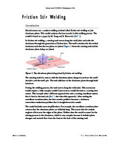
friction of the rotating tool shoulder and probe with the workpiece and by the severe plastic deformation of the metal in the workpiece. The localised heating softens the material around the probe. The tool rotation and translation cause the movement of the material from the front to the back of the probe. The tool shoulder also restricts the metal flow under the bottom shoulder surface. Because of the various geometrical features of the tools, the material movement around the probe can be extremely complex and significantly different from one tool to the other. In this study, some critical issues related to the FSW/P tools (shoulders and probes) are briefly summarised.
Tool types 1 Principle of FSW process1,3
of the sheets or plates to be joined and traversed along the joint line,3–5 as schematically shown in Fig. 1. The material is softened by frictional heating, and the forging pressure from the shoulder reconsolidates the material behind the tool. Friction stir processing (FSP) is a variant of FSW that involves traversing of the friction stir tool through the material in the absence of a joint interface. Friction stir welding is considered to be the most significant development in metal joining in the past decades. It is an emergent green technology due to its energy efficiency (low heat input), sustainable utilisation of natural resources (less material waste, reduced material lead time, part count reduction, high weld quality and performance, longer life cycle), reduced environmental impact (no shielding gases required, no fumes/spattering/ ozone produced, part cleaning requirements reduced, filler material addition not necessary) and process versatility (adaptable welding orientations and different thicknesses, microstructures, and compositions).5–8 As a solid state joining process, FSW is performed below the melting temperature of the material, which thus minimises/avoids some typical defects encountered in fusion welding such as cracking, porosity and alloying element loss. Nowadays FSW has become a practical joining technique for Al and other low strength alloys. However, for high strength alloys such as Ti, Ni and steel, cost effective welding and long tool life remain as subjects for research development and processing technology optimisation. The main roles of the FSW/P tools5 are to heat the workpiece, induce material flow and constrain the heated metal beneath the tool shoulder. Heating is created by the
There are three types of FSW/P tools, i.e. fixed, adjustable and self-reacting, as illustrated in Fig. 2. The fixed probe tool corresponds to a single piece comprising both the shoulder and probe (Fig. 2a). This tool can only weld a workpiece with a constant thickness due to the fixed probe length. If the probe wears significantly or breaks, the whole tool must be replaced. As an extreme example of the fixed tool for friction stir spot welding (FSSW), an FSSW tool consisting only of a single shoulder with no probe was reported.9–11 The adjustable tool consists of two independent pieces, i.e. separate shoulder and probe, to allow adjustment of the probe length during FSW12,13 (Fig. 2b). In this design, the shoulder and probe can be manufactured using different materials and the probe can be easily replaced when worn or damaged. Moreover, the adjustable probe length can allow welding of variable and multiple gauge thickness workpieces, and implementation of strategies for filling the exit hole, left at the end of the friction stir weld. Both the fixed and the adjustable tools often require a backing anvil. The bobbin type tool (Fig. 2c) is made up of three pieces: top shoulder, probe and bottom shoulder.14,15 This tool can accommodate multiple gauge thickness joints due to the adjustable probe length between the top and bottom shoulders.16,17 No backing anvil is needed but the bobbin type tool can only work perpendicularly to the workpiece surface. In contrast, the fixed and adjustable tools can be tilted longitudinally and laterally.
Tool shapes Shoulder shapes Tool shoulders are designed to frictionally heat the surface regions of the workpiece, produce the downward forging action necessary for welding consolidation and
2 a fixed, b adjustable and c bobbin type tools5
Canadian Metallurgical Quarterly
2012
VOL
51
NO
3
251
Zhang et al.
Review of tools for FSW/P
3 Shoulder shapes and features
constrain the heated metal beneath the bottom shoulder surface. Figure 3 summarises the typical shoulder outer surfaces, the bottom end surfaces and the end features. The shoulder outer surface usually has a cylindrical shape, but occasionally, a conical surface is also used.3 Generally, it is expected that the shape of the shoulder outer surface (cylindrical or conical) has an insignificant influence on the welding quality because the shoulder plunge depth is typically small (i.e. 1–5% of the gauge thickness).3 It is noteworthy that Tozaki et al.9 and Bakavos and Prangnell10 reported that sound welds can be obtained using a probe free shoulder tool in which the bottom scrolled shoulder surface feature played a significant role in stirring the materials. In this case, the shoulder outer surface shape and feature may also become important. As demonstrated in Fig. 3, three types of shoulder end surfaces are typically used.5 Of these, the flat shoulder end surface is the simplest design. The main disadvantage of this design is that the flat shoulder end surface is not effective for trapping the flowing metal material under the bottom shoulder, leading to the production of excessive material flash. To this end, a concave shoulder end surface was designed and has now become popular for restricting material extrusion from the sides of the shoulder.18–20 This simple shape is easy to machine and can produce sound welds. The concave shoulder inclines only a small angle (6–10u) from the flat shoulder end surface. During tool plunging, the material displaced by the probe is fed into tool shoulder cavity. Hence the concave surface profile of the tool shoulder serves as an escape volume or reservoir for the displaced material from the probe. By exerting a downward applied pressure on the tool, the displaced material held in the concave shoulder profile renders a forging action on the material behind the tool. Then the forward movement of the tool forces new material into the cavity under the shoulder and pushes the existing material behind the probe. The proper
252
Canadian Metallurgical Quarterly
2012
VOL
51
NO
3
operation of this shoulder requires the tilting of the tool 1–3u from the normal of the workpiece against the direction of travel. This is necessary to maintain the material reservoir and to enable the trailing edge of the shoulder tool to produce a compressive forging force on the weld.21,22 It can also lead to higher forging and hydrostatic pressures, which may promote material stirring and improve nugget integrity.23 Another possible end shape of the shoulder is a convex profile.24,25 Early attempts at TWI for the convex end surface were unsuccessful because the convex profile was determined to push the material away from the probe.26 However, it was reported that a smooth convex end surface shoulder with a 5 mm diameter was successfully used to weld 0?4 mm thick AZ31 Mg alloy sheets,27 inevitable because of the thin gauge thickness (i.e. ,1 mm) for which the end shape of the shoulder becomes insignificant. Although the main advantage of the convex shoulder profile is that it can attain contact with the workpiece at any location along the convex end surface, and thereby, accommodate differences in flatness or thickness between the two adjoining workpieces,25 the inability of the smooth end surface to prevent material displacement away from probe causes weld integrity issues. The shoulder end surfaces can also contain some features to increase material friction, shear and deformation for increased workpiece mixing and higher weld quality.24,28 The typical shoulder end styles include flat (smooth or featureless), scrolls, ridges, knurling, grooves and concentric circles,14 as revealed in Fig. 3. These features can be applied to concave, flat or convex shoulder ends. Scrolls are the most commonly used shoulder feature.29,30 The typical scrolled shoulder consists of a flat end surface with a spiral channel cut from the edge towards the centre. The channels help the material flow from the edge of the shoulder to the probe, thus eliminating the need to tilt the tool. The concave smooth shoulder end tends to be pushed away from the workpiece
Zhang et al.
Review of tools for FSW/P
4 FSW/P tool probes
top surface during FSW at a high travel speed because the stirred material is continuously trapped in the reservoir/ cavity under the shoulder, as described above.5,6 However, the concave shoulder combined with a scrolled feature can reduce the tool lift during high speed welding.26 An additional advantage of the scrolled shoulder is the elimination of the undercut defect produced by the concave tool and a corresponding reduction in flash due to the improved coupling between the shoulder and the workpiece by entrapping the plasticised material within the special reentrant features. The material inside the channels (reentrant features) is also continually sheared from the workpiece surface, thereby increasing the deformation and frictional heating at the surface.5,31,32 In addition, combining the scroll end surface with a convex shoulder design prevents material displacement away from probe and takes advantage of the greater flexibility in the contact area between the shoulder and the workpiece, which then improves the mismatch tolerance of the joint, increases the ease of joining different thicknesses and promotes the ability to weld complex curvatures.
Probe shapes The friction stirring probe can produce deformational and frictional heating. Ideally, it is designed to disrupt the contacting surfaces of the workpiece, shear the material in front of the tool and move the material behind the tool. The depth of deformation and tool travel speed are mainly governed by the probe.1 Figure 4 summarises the probe shapes and their main features. The end shape of the probe is either flat or domed. The flat bottom probe design that emphasises ease of manufacture is currently the most commonly used
form.33,34 The main disadvantage of the flat probe is the high forge force during plunging. In contrast, a round or domed end shape can reduce the forge force and tool wear upon plunging, increase tool life by eliminating local stress concentration and improve the quality of the weld root directly at the bottom of the probe.35 These benefits are apparently maximised when the dome radius is 75% of the probe diameter.35 As the dome radius decreases, the weld quality was often comprised.5,35 This can be reasoned on the basis of the surface velocity of a rotating cylindrical probe that increases from zero at the centre to a maximum value at the edge. The local surface velocity coupled with the friction coefficient between the probe and the metal determines the deformation during friction stirring. The higher surface velocity at the probe edge can increase its stirring power and hence promote the metal flow under the probe end.35 The lowest point of a round bottom probe has a lowest velocity and the least stirring action. The FSW/P probes usually have a cylindrical outer surface but a tapered outer shape can also be used as indicated in Fig. 4. In particular, cylindrical probes have been widely used for joining plates up to 12 mm thick, but for thicker plates the process operating window to maintain weld integrity becomes considerably limited (low travel speed, high rotational speed).36 With the tapered probe, the higher frictional heat increases the plastic deformation because of the larger contact area of the probe with the workpiece.37 The tapered probe also promotes a high hydrostatic pressure in the weld zone,37 which is extremely important for enhancing the material stirring and the nugget integrity. However, the high temperature and hydrostatic pressure may lead to severe tool wear.
Canadian Metallurgical Quarterly
2012
VOL
51
NO
3
253
Zhang et al.
Review of tools for FSW/P
5 Probe types developed at TWI for various material thicknesses and joint types44
The probe outer surfaces can have different shapes and features including threads, flats or flutes. Threadless probes are chosen for high strength or highly abrasive alloys as the threaded features can be easily worn away. For example, Loftus et al.38 used a featureless cylindrical probe to friction stir weld 1?2 mm thick b 21S Ti. The threadless probe has also been used to study material flow as a baseline.39 However, threaded probes are most widely used for FSW/P. Specifically, a left hand threaded probe under clockwise rotation causes the material to be drawn down by the threads along the probe surface.5,6 The material may circulate multiple times around the tool before being deposited behind the tool. This phenomenon promotes material stirring, void closure and oxide breakdown.40,41 Thomas et al.24 found that the addition of flat features can change material movement around a probe. This is due to the increased local deformation and turbulent flow of the plasticised material by the flats acting as paddles. Colligan et al.30 demonstrated that a reduction in transverse force and tool torque was directly proportional to the number of the flats placed on a tapered shoulder. Zettler et al.39 welded 4 mm thick 2024-T351 and 6056-T4 Al alloys using three different tapered probe designs: nonthreaded, threaded and threaded with flats. It was found that the non-threaded probe produced voids, while the two threaded probes produced fully consolidated welds. The flats on the probe act as the cutting edge of a cutter. The material is trapped in the flats and then released behind the tool, promoting more effective mixing. The addition of the flats was also shown to increase the temperature and nugget area.5,42 The threaded probes
6 a Worl and b MX Triflute tools44,45
254
Canadian Metallurgical Quarterly
2012
VOL
51
NO
3
with flutes function similarly to trap the material in the flutes downwards and produce integral welds.43 Owing to the progress in the understanding of material flow, the tool geometries have evolved significantly. The conventional cylindrical threaded probe has been well used for butt welding of Al alloys up to 12 mm in thickness.5 For thicker plates, more complex features on the probe have been added to favour material flow and mixing, and reduce process loads. For examples, Whorl and MX Triflute tools developed by TWI44–46 can weld Al alloys up to 50–60 mm in thickness (Fig. 5). These typical tool features are shown in Fig. 6. In addition, these tools can weld at very high speeds, while achieving integral welds with good surface quality. Both Whorl and MX Triflute probes with flat or reentrant features can reduce the probe volume and achieve a high swept rate. As a critical parameter in FSW/P tool design, the swept rate is defined as the ratio of the dynamic volume (volume swept by the probe during rotation) to the static volume (volume of the probe itself).5 A tool design with a higher swept rate is reported to reduce the voids and allow the surface oxides to be more effectively disrupted and dispersed within the nugget due to the stronger stirring and mixing action for the material flow. In conventional FSW, the dynamic/static volume ratio can be increased via the use of the reentrant features, threads with flutes and/or flats machined into the probe.43 Typically, the Worl and MX Triflute probes can reduce the displaced volume by about 60–70%, as can be seen in Table 1.3,47,48 The swept rates for welding 25 mm thick plates are 1?1 for conventional cylindrical probe with threads, 1?8 for the Worl and 2?6 for the MX
*Ratio of probe is the volume of the probe with features (threaded, flutes and/or flat) to the volume of the probe with the same shape but without features.
Tapered with threads 0.4 1.8 Yes Butt Inclined cylindrical with threads 1 Up to probe angle No Lap Tapered with threads 0.4 1.8 No Butt Schematics
Tool probe shapes Ratio of probe* Swept rate Rotary reversal Joint type
Cylindrical with threads 1 1.1 No Butt
Worl Cylindrical Tool
Table 1 Friction stir welding tools designed at TWI3,47,48
MX Triflute
Tapered with threads and flutes 0.3 2.6 No Butt
Flared-Triflute
Triflute, flared out 0.3 2.6 No Lap
Re-stir A-skew
Zhang et al.
Review of tools for FSW/P
7 Flared-Triflute tools:47 a neutral, b left and c right hand flutes
Triflute probes. These design features for the Whorl and MX Triflute probes were reported to reduce the welding forces, enable easier flow of the plasticised material, facilitate the downward material flow and increase the interface area between the probe and the plasticised materials in order to increase heat generation.47,48 It has been reported that 75 mm thick 6082-T6 Al plates can be successfully welded using a Worl tool in two passes, i.e. one pass for the upper surface and the other pass for the lower surface, each side giving y38 mm in penetration depth. Also a thickness of up to 50 mm has been successfully friction stir welded in a single pass using the Whorl and MX Triflute tools.46,47 It has been reported that lap welding is more difficult than butting welding45,47 because: (i) wider welds are necessary to transmit the load properly in the manufactured structure (ii) the hooking defect needs to be avoided or reoriented to ensure maximum strength (particularly fatigue strength).40,49 This defect is referred to the deformation deviated from the original straight and flat contact interface between the top and bottom sheets49 (iii) the oxides at the sheet interface are more difficult to disrupt for the lap configuration. For lap welding, a conventional cylindrical threaded probe resulted in excessive thinning of the top sheet, causing significantly reduced bend properties.5 Recently, two new probe geometries, Flared-Triflute with the flute lands being flared out (Fig. 7) and A-skew with the probe axis being slightly inclined with respect to the machine spindle (Fig. 8) were developed for improved weld quality.3,47 The Flared-Triflute and A-skew tools are reported to:
a side view; b front view; c swept region encompassed by skew action 8 A-skew tools47
Canadian Metallurgical Quarterly
2012
VOL
51
NO
3
255
Zhang et al.
Review of tools for FSW/P
9 a tool diameters versus workpiece thickness and b relation between tool diameters3,6,32–47
(i) increase the swept rates (2?6 for Flared-Triflute as shown in Table 1), and thereby increase the flow path around and underneath the probe (ii) widen the welding region due to the flared-out flute lands in the Flared-Triflute and the skew action in the A-skew probes (iii) improve the mixing action and favour the oxide fragmentation and dispersal at the weld interface (iv) provide an orbital forging action at the weld root due to the skewed action and hence improve weld quality in this region. Compared to the conventional threaded tools, FlaredTriflute and A-skew probes resulted in doubled welding speed, about 20% reduction in axial forge force, and significantly widened welding region (.150% of the probe diameter compared to 110% for the conventional threaded probe). Therefore, Thomas and Dolby50 recommended that both Flared-Triflute and A-skew probes are suitable for the lap and T welds where joining interface is parallel to the machine axis. An alternate approach for maintaining ease of tool design and manufacturing, has been to apply conventional shoulder/probe profiles and perform a double welding pass (or tandem overlap welding by the Twin Stir process44,45) to join lap configurations without defects.51
Tool dimensions As shown in equation (1), the heat input is a function of the shoulder radius to the third power but depends only linearly on the applied forge force and the rotational speed.4,5 Therefore, the energy input in FSW/P is strongly dependent on the shoulder size. Furthermore, the Z axis forge force is also a function of the shoulder radius.6,48 q0 ~4=3p2 mPvR3
(1)
where q0 is the net power (W), m is the effective friction coefficient between the workpiece and the tool, P is the pressure (MPa), v is the rotation speed (rev min21), and R is shoulder radius (mm). Figure 9a summarises the shoulder diameters as a function of sheet thickness for 53 butt set-ups including Al, Mg, Cu, Ti, Ni and steel reported in the
256
Canadian Metallurgical Quarterly
2012
VOL
51
NO
3
literature.3,6,16–45 A clear trend is observed using a least square approximation: the shoulder diameter is y2?2 times the workpiece thickness plus a constant of 7?3 mm.52 This relationship is reasonable considering that with increasing thickness, more energy input is necessary and hence a larger shoulder diameter is required to generate the heat. Similarly, a general tendency between probe diameter and sample thickness is also shown in Fig. 9a. The probe diameter is 0?8 times the sample thickness plus a constant of 2?2 mm. Reynolds and Tang52 used 8–12 mm probes and found that the probe diameter did not appear to influence the required X-axis force and the specific weld energy. The coupled probe and shoulder diameter is summarised in Fig. 9b. The shoulder diameter is 2?1 times the probe diameter plus 4?8 mm. However, the most commonly used ratio of shoulder-to-probe diameter is 3.53,54
Tool materials Tool material characteristics can be critical for FSW. The candidate tool material depends on the workpiece material and the desired tool life as well as the user’s own experiences and preferences. Ideally, the tool material should have the following properties:5 (i) higher compressive yield strength at elevated temperature than the expected forge forces onto the tool (ii) good strength, dimensional stability and creep resistance (iii) good thermal fatigue strength to resist repeated heating and cooling cycles (iv) no harmful reaction with the workpiece material (v) good fracture toughness to resist the damage during plunging and dwelling (vi) low coefficient of thermal expansion between the probe and the shoulder materials to reduce the thermal stresses (e.g. the use of a thermal barrier coating for polycrystalline cubic boron nitride (PCBN) tools to prevent heat from moving into the tungsten carbide shank18) (vii) good machinability to ease manufacture of complex features on the shoulder and probe (viii) low or affordable cost.
Zhang et al.
Review of tools for FSW/P
10 Features of PCBN tool system5,54
The tool materials used for FSW/P are briefly summarised in Tables 2 and 3. Tool steel is the most widely used tool material for aluminium alloys. Within the tool steels, AISI H13, a chromium–molybdenum hot worked air hardening steel, has been the most commonly used.55,56 Nickel and cobalt based superalloys, which were initially designed for aircraft engine components offer high strength, ductility, good creep and corrosion resistance as tool materials. However, the greater difficulty in machining of superalloys impedes the manufacture of complex features such as flutes and flats on the tool profile. Refractory metals, such as tungsten, molybdenum, niobium and tantalum, are used as tool materials due to their high temperature strength. Many of these alloys are produced as single phase materials, which enables the mechanical properties to be maintained up to 1000–1500uC. However, powder processing is the primary production method for the refractory alloys and, as such, the material costs are relatively high. Carbide materials that are commonly used as machining tools offer superior wear resistance and the reasonable fracture toughness as a probe/shoulder material for FSW at ambient temperature. Ceramic particle reinforced metal matrix composites have also been used as tool materials, but the brittle nature of the composite can result in fracture during the tool plunging phase. Polycrystalline cubic boron nitride, which was originally developed for turning and machining of tool steels, cast irons and superalloys,5,18 is currently the well accepted friction stir tool material due to its high mechanical and thermal performance. However, the relatively high costs associated with the manufacture of PCBN (i.e. sintering of cubic boron nitride using a high temperature high pressure process) as well as the size limitation, poor machinability and low fracture toughness pose
challenges for widespread application as a friction stir tool material (especially for complex geometries). Figure 10 presents the main features of a PCBN tool system.57 A thermal barrier between the PCBN probe and the tungsten carbide shank is used to reduce the transfer of frictional heat to the tool main body.18
Tool wear Excessive tool wear changes the tool shape, thereby increasing the probability of defect generation, and possibly degrading the weld quality. The exact wear mechanism depends on the interaction between the workpiece and the tool materials, the selected tool geometry and the welding parameters. For example, in the case of PCBN tools, the wear at low tool rotation rate is mainly caused by adhesive wear (also known as scoring, galling or seizing), while the wear at high tool rotation rate is due to abrasive wear.5,57 Shindo et al.58 and Prado et al.59 reported on the tool wear for Al–20SiC (Ref. 58) and Al–20Al2O3 (Ref. 59) particle reinforced composites. The tool used consisted of an AISI oil hardened tool steel initially with screw nib right hand threads. Owing to the abrasive particles in the Al-MMCs, the threads of the probe wore away, leading to a slightly curve shaped probe, as shown in Fig. 11. Astoundingly, the self-optimised shape (worn tool) with no threads could result in homogenous and integral welds without further visible tool wear. These observations suggest that tool consumption can be greatly minimised even for MMCs when using the optimised tool shape. Hence to reduce tool wear and extend the tool life, understanding and controlling the material flow associated with the probe profile in the solid state are important. It is noteworthy that the self-optimised shape
Table 2 Friction stir welding tool materials used for butt welding5 Tool materials/mm Workpiece materials
Tool steel
Ni and Co based superalloys
Refractory metals
Carbides and metal matrix composites (MMCs)
PCBN
Al alloys Mg alloys Cu alloys Ti alloys Ni alloys Stainless steels Low alloy steels Al-MMC Mg-MMC
(12 (6 (11 … … … … (8 (4
(26 … (50 … … … … (6 …
… … (50 (6.35 (6.35 (6.35 (12 … …
(12 (6 … (2 … … (10 … …
(50 … (50 (6.35 (6.25 (6 (20 (10 …
Canadian Metallurgical Quarterly
2012
VOL
51
NO
3
257
258
Canadian Metallurgical Quarterly
2012
VOL
51
NO
3
WC based alloys, WC–Co based alloys TiC, TiC–Ni–W Ti–Ni–Mo PCBN
W, W-3Re, W-25Re, W- 1LaO2, Densimet (90W–10Fe–Ni) Mo based alloys: Mo–W alloys Nb Ta Carbides and MMCs
MP159 Inconel 718, 738LC, 939, 100 Waspalloy PM3030, Nimonic 90, Nimonic105 Refractory metals
SKD61 tool steel Wear resistant steel Ni/Co based alloys
Limited welding depth (,12 mm)
Difficult to machine for complex features Very expensive
Superabrasive Synthetic material, second in hardness after diamond Chemical stability Excellent wear resistance at elevated temperature
Reasonable fracture toughness at ambient temperatures Superior tool wear resistance
Single phase, and high strength maintained to nearly the melting point temperature No heat treatment
Not good for Cu alloys
Ta and Nb with high oxygen solubility at elevated temperatures lead to degraded ductility Limited material availability, long lead time, high cost, and difficult to machine Excessive tool wear due to lower strength
High melting temperature
Excellent tool wear resistance
Temperature must be kept below the precipitation temperature (typically 600–800uC) to prevent precipitate overaging and dissolution Difficult to machine
Severe tool wear for high strength materials or MMC
High strength, ductility, creep resistance and corrosion resistance
Good thermal fatigue resistance
Easy machinability Good elevated temperature strength
Visible tool wear after welding for a certain distance
Low cost
Tool steel
AISI H13 AISI 4340, O1 tool steel
Disadvantages
Advantages
Tool materials
Table 3 Characterics of FSW tool materials for butt welding5,43–62
Mainly used for high strength and wear resistant materials, such as Cu, Ti and Ni alloys, steel and Al-MMC
Mainly used for Al, Mg and Ti alloys, and steel
To optimise probe shape: thread free probes
Mainly used for high melting point materials such as Cu, Ti, Ni alloys and steel
Mainly used for Al, Cu alloys and Al-MMC
Surface hardening coating to increase wear resistance Probe shape optimisation Widely used for Al, Mg, Cu, Al-/Mg-MMC
Comments
Zhang et al. Review of tools for FSW/P
Zhang et al.
Review of tools for FSW/P
11 Wear features of probes for Al-MMC at 1000 rev min21: welding speeds at a 1, b 3, c 6 and d 9 mm s21; e probe wear (vol.-%) versus weld length and f wear rate versus weld speed59
does change somewhat with increasing welding speed due to increasing tool wear.54 For FSSW, severe tool wear has been reported after producing hundreds of welds. For light metals such as Al and Mg alloys, the welding tool is commonly made of tool steel and suffers from little wear. It was reported that no significant wear was found on the steel tool even after hundreds of thousands of spot welds for Al. However, the steel tools are not suitable for high melting point materials such as, Ti, Ni, steels, etc. For these high strength materials, the welding tools are usually made of hard metals, carbides and metal matrix composites with superior thermal and wear resistance at temperatures
higher than 1000uC, such as WC–Co, TiC and PCBN.60 Figure 12 shows the external WC–Co tool shape after some welds.61 It clearly reveals that the extreme wear for WC–Co tools mainly occurred between the probe centre and the external edge.
Conclusions For the past 20 years, significant progresses in FSW and processing have been obtained. Various welding tools have already been designed throughout the entire process evolution. To date, low cost and long life welding and processing tools have been well developed for low strength materials such as Al and Mg alloys. However, long life tools with affordable costs are still unavailable for abrasive materials such as particle reinforced metal matrix composites, and high strength materials such as Ti, Ni, steels, etc. To this end, further efforts should concentrate on developing new tool materials and designing new effective special tools.
Acknowledgement Financial support from Defence Research and Development Canada (DRDC) Atlantic, Canada is gratefully acknowledged. a, e before welding; b, f after 100; c, g after 300; d, h after 500 spot welds61 12 External shape of WC–Co tools
References 1. W. M. Thomas, E. D. Nicholas, J. C. Needham, M. G. Murch, P. Temple-Smith and C. J. Dawes: GB Patent no. 9125978?8, 1991.
Canadian Metallurgical Quarterly
2012
VOL
51
NO
3
259
Zhang et al.
Review of tools for FSW/P
2. C. Dawes and W. Thomas: ‘Friction stir joining of aluminium alloys’, TWI Bull., 1995, 6, 124–127. 3. R. S. Mishra and Z. Y. Ma: ‘Friction stir welding and processing’, Mater. Sci. Eng. R, 2005, 50R, 1–78. 4. M. Iordachescu, E. Scutelnicu and D. Iordachescu: ‘Fundamentals of the process and tools design: friction stir processing of materials’, Weld. Equip. Technol., 2006, 17, 63–72. 5. R. S. Mishra and M. W. Mahoney: ‘Friction stir welding and processing’; 2007, Materials Park, OH, ASM International. 6. L. Dubourg and P. Dacheux: ‘Design and properties of FSW tools: a literature review’, Proc. 6th Int. Symp. on ‘Friction stir welding’, Vol. 52, No. 4, 62; 2006, Saint-Sauveur, PQ, TWI. 7. R. S. Mishra, M. W. Mahoney, S. X. McFadden, N. A. Mara and A. K. Mukherjee: ‘High strain rate superplasticity in a friction stir processed 7075 Al alloy’, Scr. Mater., 2000, 42, 163. 8. R. S. Mishra and M. W. Mahoney: ‘Friction stir processing: a new grain refinement technique to achieve high strain rate superplasticity in commercial alloys’, Mater. Sci. Forum, 2001, 357–359, 507–514. 9. Y. Tozaki, Y. Uematsu and K. Tokaji: ‘A newly developed tool without probe for friction stir spot welding and its performance’, J. Mater. Process. Technol., 2010, 210, 844–851. 10. D. Bakavos and P. B. Prangnell: ‘Effect of reduced or zero pin length and anvil insulation on friction stir spot welding thin gauge 6111 automotive sheet’, Sci. Technol. Weld. Join., 2009, 14, 443– 456. 11. D. Bakavos, Y. C. Chen, L. Babout and P. B. Prangnell: ‘Material interactions in a novel pinless tool approach to friction stir spot welding thin aluminum sheet’, Metall. Mater. Trans. A, 2011, 42A, 1266–1282. 12. R. J. Ding and P. A. Oelgoetz: ‘Auto-adjustable probe tool for friction stir welding’, US Patent no. 5893507, 1999. 13. R. J. Ding: ‘Force characterization on the welding pin of a friction stir welding retractable pin-tool using aluminum-lithium 2195’, Proc. 2nd Int. Conf. on ‘Friction stir welding’, Gothenburg, Sweden, June 2000, TWI. 14. W. M. Thomas, E. D. Nicholas and S. D. Smith: ‘Friction stir welding-tool developments’, Proc. Aluminum Automotive and Joining Sessions, 213–224; 2001, Warrendale, PA, TMS. 15. M. Skinner and R. L. Edwards: ‘Improvements to the FSW process using the self-reacting technology’, Mater. Sci. Forum, 2003, 426, 2849–2854. 16. G. Sylva, R. Edwards and T. Sassa: ‘A feasibility study for selfreacting pin tool welding of thin section aluminum’, Proc. 5th Int. Conf. on ‘Friction stir welding’, Metz, France, September 2004, TWI. 17. F. Marie, D. Allehaux and B. Esmiller: ‘Development of the bobbin tool technique on various Al alloys’, Proc. 5th Int. Conf. on ‘Friction stir welding’, Metz, France, September 2004, TWI. 18. C. D. Sorenson, T. W. Nelson, S. M. Packer and R. J. Steel: ‘Innovative technology applications in FSW of high softening temperature materials’, Proc. 5th Int. Conf. on ‘Friction stir welding’, Metz, France, September 2004, TWI. 19. A. P. Reynolds and W. D. Lockwood: ‘Digital image correlation for determination of weld and base metal constitutive behavior’, Proc. 1st Int. Conf. on ‘Friction stir welding’, Thousand Oaks, CA, USA, June 1999, TWI. 20. T. W. Nelson, B. Hunsaker and D. P. Field: ‘Local texture characterization of friction stir welds in 1100 aluminum’, Proc. 1st Int. Conf. on ‘Friction stir welding’, Thousand Oaks, CA, USA, June 1999, TWI. 21. M. A. Sutton, A. P. Reynolds, B. Yang and R. Taylor: Mode I fracture and microstructure for 2024-T3 friction stir welds’, Mater. Sci. Eng. A, 2003, A354, 6–16. 22. J. Lumsden, G. Pollock and M. Mahoney: ‘Effect of tool design on stress corrosion resistance of FSW AA7050-T7451’, in ‘Friction stir welding and processing III’, 19–25; 2005, San Francisco, CA, TMS. 23. L. Dubourg, F. O. Gagnon, L. St-Georges, M. Jahazi and F. G. Hamel: ‘Process window optimization for FSW of thin and thick sheet Al alloys using statistical methods’, Proc. 6th Symp. on ‘friction stir welding’, Saint Sauveur, PQ, Canada, October 2006, TWI. 24. W. M. Thomas, E. D. Nicholas, J. C. Needham, P. Temple-Smith, S. W. K. W. Kallee and C. J. Dawes: ‘Friction stir welding’, UK Patent Application 2306366, 1996.
260
Canadian Metallurgical Quarterly
2012
VOL
51
NO
3
25. K. Colligan: ‘Tapered friction stir welding tool’, US Patent no. 6669075, 2003. 26. K. J. Colligan and J. R. Pickens: ‘Friction stir welding of aluminum using a tapered shoulder tool’, in ‘Friction stir welding and processing III’, 161–170; 2005, San Francisco, CA, TMS. 27. T. Nishihara and Y. Nagasaka: ‘Development of micro-FSW’, Proc. 5th Int. Conf. on ‘Friction stir welding’, Metz, France, September 2004, TWI. 28. C. J. Dawes and W. M. Thomas: ‘Development of improved tool designs for friction stir welding of aluminum’, Proc. 1st Int. Conf. on ‘Friction stir welding’, Thousand Oaks, CA, USA, June 1999, TWI. 29. S. Brinckmann, A. von Strombeck, C. Schilling, J. F. dos Santos, D. Lohwasser and M. Kocak: ‘Mechanical and toughness properties of robotic-FSW repair welds in 6061-T6 aluminum alloys’, Proc. 2nd Int. Conf. on ‘Friction stir welding’, Gothenburg, Sweden, June 2000, TWI. 30. K. J. Colligan, J. Xu and J. R. Pickens: ‘Welding tool and process parameter effects in friction stir welding of aluminum alloys’, in ‘Friction stir welding and processing II’, 181–190; 2003, Warrendale, PA, TMS. 31. S. Packer, T. Nelson, C. Sorensen, R. Steel and M. Matsunaga: ‘Tool and equipment requirements for friction stir welding ferrous and other high melting temperature alloys’, Proc. 4th Int. Conf. on ‘Friction stir welding’, Park City, UT, USA, May 2003, TWI. 32. C. D. Sorensen, T. W. Nelson and S. M. Packer: ‘Tool material testing for FSW of high-temperature alloys’, Proc. 3rd Int. Conf. on ‘Friction stir welding’, Kobe, Japan, September 2001, TWI. 33. T. W. Nelson, H. Zhang and T. Haynes: ‘Friction stir welding of aluminum MMC 6061-boron carbide’, Proc. 2nd Int. Conf. on ‘Friction stir welding’, Gothenburg, Sweden, June 2000, TWI. 34. B. London, M. Mahoney, M. Bingel, M. Calabrese, R. H. Bossi and D. Waldron: ‘Material flow in friction stir welding monitored with Al–SiC and Al–W composite markers’, in ‘Friction stir welding and processing II’, 3–12; 2003, Warrendale, PA, TMS. 35. C. J. Dawes, P. L. Threadgill, E. J. R. Spurgin and D. G. Staines: ‘Development of the new friction stir technique for welding aluminum phase II’, TWI member report, Cambridge, UK, 1995. 36. S. P. Vaze, J. Xu, R. J. Ritter, K. J. Colligan, J. J. Fisher, Jr and J. R. Pickens: ‘Friction stir processing of aluminum alloy 5083 plate for cold bending’, Mater. Sci. Forum, 2003, 426–432, 2979–2986. 37. R. W. Fonda, J. F. Bingert and K. J. Colligan: ‘Texture and grain evolutions in a 2195 friction stir weld’, Proc. 5th Int. Conf. on ‘Friction stir welding’, Metz, France, September 2004, TWI. 38. Z. Loftus, J. Takeshita, A. Reynolds and W. Tang: ‘An overview of friction stir welding beta 21S titanium’, Proc. 5th Int. Conf. on ‘Friction stir welding’, Metz, France, September 2004, TWI. 39. R. Zettler, S. Lomolino, J. F. dos Santos, T. Donath, F. Beckmann, T. Lipman and D. Lohwasser: ‘A study of material flow in FSW of AA2024-T351 and AA 6056-T4 alloys’, Proc. 5th Int. Conf. on ‘Friction stir welding’, Metz, France, September 2004, TWI. 40. P. A. Colegrove and H. R. Shercliff: ‘Development of trivex friction stir welding tool. Part 1: two-dimensional flow modeling’, Sci. Technol. Weld. Join., 2004, 9, (4), 345–351. 41. P. A. Colegrove and H. R. Shercliff: ‘Experimental and numerical analysis of aluminum alloy 7075-T7351 friction stir welds’, Sci. Technol. Weld. Join., 2003, 8, (5), 360–368. 42. W. M. Thomas, I. M. Norris, D. G. Staines and E. R. Watts: ‘Friction stir welding – process development and variant techniques’, Proc. SME Summit, Milwaukee, WI, USA, August 2005, SME. 43. M. Aissani, S. Gachi, F. Boubenider and Y. Benkedda: ‘Design and optimization of friction stir welding tool’, Mater. Manuf. Processes, 2010, 25, (11), 1199–1205. 44. W. M. Thomas, E. D. Nicholas and S. D. Smith: ‘Friction stir welding-tool developments’, Proc. TMS 2001 Aluminum Automotive and Joining Sessions, 213; 2001, Warrendale, PA, TMS. 45. W. M. Thomas, D. G. Staines, I. M. Norris and R. de Frias: ‘Friction stir welding – tools and developments’, Weld. World, 2002, 47, (11–12), 10–17. 46. W. M. Thomas, S. A. Lockyer, S. W. Kalee and D. G. Staines: ‘Friction stir welding: an update on recent developments’, Proc.
Zhang et al.
47.
48.
49.
50.
51.
52.
53.
54.
Conf. on ‘Stressed components in aluminium alloys’, Birmingham, UK, April 2003, ImechE. W. M. Thomas, K. I. Johnson and C. S. Wiesner: ‘Friction stir welding recent developments in tool and process technologies’, Adv. Eng. Mater., 2003, 5, (7), 485–490. R. Nandan, T. DebRoy and H. K. D. H. Bhadeshia: ‘Recent advances in friction stir welding process, weldment structure and properties’, Prog. Mater. Sci., 2008, 53, 980–1023. X. Cao and M. Jahazi: ‘Effect of tool rotational speed and probe length on lap joint quality of a friction stir welded magnesium alloy’, Mater. Des., 2011, 32, (1), 1–11. W. M. Thomas and R. E. Dolby: ‘Friction stir welding developments’, Proc. 6th Int. Trends in Welding Research, 203–211; 2003, Materials Park, OH, ASM International. L. Dubourg, A. Merati and M. Jahazi: ‘Process optimisation and mechanical properties of friction stir lap welds of 7075-T6 stringers on 2024-T3 skin’, Mater. Des., 2010, 31, 3324–3330. A. P. Reynolds and W. Tang: ‘Alloy, tool geometry, and process parameter effects on friction stir weld energies and resultant FSW joint properties’, in ‘Friction stir welding and processing’, 15–23; 2001, Indianapolis, Indiana, TMS. X. G. Chen, M. D. Silva, P. Gougeon and L. St-Georges: ‘Microstructure and mechanical properties of friction stir welded AA6063-B4C metal matrix composites’, Mater. Sci. Eng. A, 2009, 518, 174–184. R. A. Prado, L. E. Murr, D. J. Shindo and K. F. Soto: ‘Tool wear in the friction stir welding of aluminum alloy 6061z20% Al2O3: a preliminary study’, Scr. Mater., 2001, 45, 75–80.
Review of tools for FSW/P
55. A. H. Feng and Z. Y. Ma: ‘Formation of Cu2FeAl7 phase in friction stir welded SiCp/Al-Cu-Mg composite’, Scr. Mater., 2007, 57, 1113–1116. 56. M. Najafi, A. M. Nasiri and A. H. Kokabi: ‘Microstructure and hardness of friction stir processed AZ31 with SiCp’, Int. J. Mod. Phys. B, 2008, 22B, (18–19), 2879–2885. 57. M. Collier, R. Steel, T. Nelson, C. Sorensen and S. Packer: ‘Grade development of polycrystalline cubic boron nitride for friction stir processing of ferrous alloys’, Proc. 4th Int. Conf. on ‘Friction stir welding’, Park City, UT, USA, May 2003, TWI. 58. D. J. Shido, A. R. Rivera and L. E. Murr: ‘Shape optimization for tool wear in the friction stir welding of cast Al359-20% SiC MMC’, J. Mater. Sci., 2002, 37, 4999–5005. 59. R. A. Prado, L. E. Murr, K. F. Soto and J. C. McClure: ‘Selfoptimization in tool wear for friction stir welding of Al 6061z20% Al2O3 MMC’, Mater. Sci. Eng. A, 2003, A349, 156–165. 60. Y. Hovanski, M. L. Santella and G. J. Grant: ‘Friction stir spot welding of hot-stamped boron steel’, Scr. Mater., 2007, 57, 873– 876. 61. D. H. Choi, C. Y. Lee, B. W. Ahn, J. H. Choi, Y. M. Yeon, K. Song, H. S. Park, Y. J. Kim, C. D. Yoo and S. B. Jung: ‘Frictional wear evaluation of WC-Co alloy tool in friction stir spot welding of low carbon steel plates’, Int. J. Refract. Met. Hard Mater., 2009, 27, 931–936. 62. A. Kumar, D. P. Fairchild, M. L. Macia, T. D. ANderson, H. W. Jin, R. Ayer and A. Ozekcin: ‘Research progress on friction stir welding of pipeline steels’, Proc. 8th Int. Pipeline Conf., Vol. 2, 711–719; 2010, Calgary, ASME.
Canadian Metallurgical Quarterly
2012
VOL
51
NO
3
261