MIE 12-032
International Conference on Mechanical, Industrial and Energy Engineering 2012 01-02 February, 2013, Khulna, BANGLADESH
Effects of Roughness Height in Forced Convective Heat Transfer: Macro to Micro Roughness Md. J. Nine1, *, Md. A. A. Mamun2, AKM Nazrul Islam2, Hyo-min Jeong1 1
Department of Mechanical and Precision Engineering, Gyeongsang National University, Institute of Marine Industry, 445 Inpyeong-dong, Tongyeong, Gyeongnam, 650-160, Korea. 2 Department of Mechanical Engineering, Khulna University of Engineering & Technology, Khulna -9203, Bangladesh.
ABSTRACT The article is about the comparative analysis of macro and micro type artificial roughness applied to enhance convective heat transfer performance under laminar and low turbulent regime. Circular ribs (e/H = 0.05, 0.1, 0.15) and nano particle porous layer (CuO particle) are fabricated over the copper substrate respectively in a rectangular duct having 7.5 cross sectional aspect ratio. Only one rib pitch to rib height ratio (P/e = 10) has been chosen for all different height ribs. Nano and micro scale porous layer is formed on the copper substrate by an etching with HNO3 acid including CuO nanoparticles having less than 100 nm in size. The result shows average turbulence intensity between two ribs decreases with decreasing roughness height on the other hand nano porous layer shows significant heat transfer efficiency (about 51 % more than bare copper plate) under laminar and low turbulent region without the effect of high turbulence. It happens though the nano porous layer causes a little additional friction loss but changes the dynamic behaviors of fluids a lot in the vicinity of heat transfer wall. Keywords: Rectangular duct, Circular rib, Nano porous layer, Friction factor, Heat Transfer. 1. Introduction Roughness effect on friction factor and heat transfer draws a great attention of researcher. Investigation of high performance heat transfer surface is an important issue in the field of heat exchanger where artificial roughness is the key to fabricate novel and effective heat transfer surface. To enhance heat transfer by means of enhanced surface applying obstacles like fin increases turbulence on the surface as well. But friction losses get higher to create high turbulence by such a macro (Ribs) size roughness that drags the system to enormous energy loss. In this circumstance only micro roughness can be capable to save energy and facilitates high efficiency in the field of heat transfer. Convection is the most usual, effective heat transfer mood greatly influenced by the artificial roughness fabricated on heat transfer surface. The article reveals a comparative and comprehensive analysis of heat transfer efficiency between rib roughened surface and nano porous layer under laminar and low turbulent regime. Early researches [1-2] just studied very limited number of rib roughness configurations and data were also acquired from limited number of locations. The effect of rib pitch to rib height variation in a tube was first studied by Webb et al. [3] and the result was formulated into a correlation. In 1993, Okamoto et al. [4] studied about two dimensional square ribs mounted on a smooth surface and they measured the water flow structure over the ribs. They found that the effects of Reynolds number on the optimum pitch ratio for augmenting turbulence seemed to be insignificant. They also reported that at the optimum pitch ratio, the pressure loss due to the ribs was maximized. This was the cost of augmentation of heat transfer. Han et al. [5] studied the heat transfer in square channel with different angle rib arrays on two * Corresponding author. Tel.: +82-10-5805-7818 E-mail address:
[email protected]
walls for P/e = 10 and e/Dh= 0.0625. They reported that the angle ribs and 'V' ribs provided higher heat transfer enhancement than the continuous ribs and the highest value is at the 60° orientation amongst the angled ribs. X. Gao and B. [6] Sunden studied the rib configuration with parallel and V-shaped into different channel aspect ratio. They found that the V-ribs pointing downstream produced highest heat transfer enhancement and friction factor and provided the best thermal performance. Parallel ribs provided better performance that V-ribs pointing upstream at high Reynolds number. Last few years there have been several investigations on rib roughened surface to optimize the shape of rib and to find the effect of rib height. R. Kamali and A.R. Binesh [7] performed a study on square, triangular, trapezoidal with decreasing height in the flow direction, and trapezoidal with increasing height in the flow direction. They found that the heat transfer coefficient are strongly affected by the rib shape and trapezoidal ribs with decreasing height in the flow direction provide higher heat transfer enhancement and pressure drop than other shapes. M. Huh et al. [8] reports the effect of rib height on heat transfer in a rectangular channel with sharp entrance at high rotation number. D.N. Ryu et al. [9] studied the characteristics of turbulent flow in channels with two dimensional ribs and three dimensional blocks. So over the years the studies have been performed to investigate various significant parameters of rib roughened surface that influence the heat transfer performance such as rib shape, rib angle, rib height (e), channel aspect ratio (AR), rib height to channel height ration (e/H) etc. In 2004, T. Kunugi et al. [10] has introduced a new system of heat transfer method between solid and fluid where they treated the heat transfer surface with the past
containing copper oxide (CuO), Carbon (C) and Alumina (Al2O3) nanoparticls having the diameter of 100 nm or less and an acid or an alkali. They revealed that the system provides high efficiency with low cost regarding the convective heat transfer. Latter the mechanism of convective heat transfer enhancement formed by nano-poraous layer is resolved by M. Shibahara [11]. They calculated energy transfer numerically by using classical molecular dynamics method to investigate the effect of surface structure from 0.1 nm to 10 nm. They found that the geometry of nanoscale structures on the surface affects the surface adsorption state and dynamic behaviors of fluid molecules. Recently R. Senthilkumar [12] showed that how the nanoparticle coating can change the surface thermal performance. They applied CNTs coating on brass extended surfaces. They explained experimentally the effect of CNTs coating on convective heat transfer performance and compared the temperature distribution for coated and non coated surface. The present study is about the comparative analysis on macro and micro roughness in convective heat transfer where the working fluid is air. The study is significant to find out the effect of micro roughness on thermal diffusion and adsorption behavior of fluid molecules in the vicinity of heat transfer surface. The overall performance obtained from micro roughness has been compared with three different macro sizes circular ribs employed in the study. The comparison between rib roughened and nano porous layer have been elaborately described in terms of friction factor and convective heat transfer. Nano porous layer does not disturb the main stream to enhance heat transfer where rib roughened surface enhances convective heat transfer occurring huge pressure drop and creating large scale of turbulence.
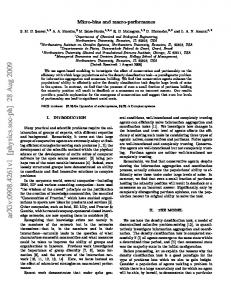
Fig. 1 Schematic diagram of device (above) and real experimental set up (inset)
2. Experiment 2.1 Experimental setup The rectangular duct is directly connected to a low pressure fan (shown in figure 1). The channel geometry is characterized by 10 mm channel height (H) and 2500 mm axial length which includes 1000 mm test section with the channel width of 75 mm. The ribbed wall is copper plate of 10 mm thickness on which circular ribs with different rib height to channel height ratio (e/H = 0.05, 0.1, 0.15) were mounted. The roughness on one principle wall of channel was created following uniform rib pitch (P) to rib height (e) ratio, P/e = 10. Air is tested fluid and the operating speed of the fan was varied by using a digital regulator to provide desired air flow rate. An orifice is installed just after the fan to measure constant flow rate constant for different roughness. Silicon rubber heating coil was perfectly attached with the help of another support plate at bottom of copper test plate and covered with 2 cm glass wool for thermal insulation in opposite of heat transfer surface. The electric heat input was 100 Watt. Seven RTD-type thermo sensors were used where two are installed at inlet and outlet of test section, five of them were precisely penetrated into the 10 mm thick heat transfer plate and spaced in equal distance to measure axial temperature distribution. Two static pressure taps were located at the bottom principle wall of channel to measure axial pressure drop across the test section. One of these tap was 45 mm upstream from the leading edge of the test section and the other was 45 mm downstream of the test section. Digital manometer is used for taking static pressure. All manipulated data has been taken after the system getting stable and it took about an hour to be stable or to be thermally equilibrium. 2.2 Turbulence Test Straight I-type probe has been calibrated and used carefully to get the stream wise flow characteristics. Velocity profile and regarding turbulence were analyzed at inlet and middle section of the duct for different scale roughness by hot wire anemometer system. Specific location of approximately 29 < x/Dh < 32 has been selected from the inlet of the duct to get the aerodynamic characteristics between two ribs at middle of duct. In Fig. 1, the position of data acquisition in the middle of duct is shown by a vertical line which is selected at the flow separation zone just downstream of the rib. Near wall data has been taken at 0.25 mm interval for first 2 mm from the heat transfer surface then rest of vertical path is taken at interval of 0.5 mm. 2.3 Fabrication of micro scale porous layer Particle of copper oxide (CuO < 100 nm, collected from Nanostructured & Amorphous Materials Inc. Houston, Texas 77084, USA) and Nitric acid having low concentration were mixed to prepare paste which was then applied all over the surface by screen coating method. Then the coating is allowed to dry for next step of washing with hot water following the procedure described by T. Kunugi et al. [10]. A thin layer of nonoparticles were observed as shown in figure. 2.
MIE12-032- 2
100 Smooth Surface - 1 Smooth Surface - 2 e/H = 0.15, 1 e/H = 0.15, 2
90
Systems reproducibility at Re = 4700
Tw, oC
80
70
60
50
40 0
10
20
30
40
50
60
x/Dh
Fig. 4 Reproducibility of Experimental Device (Axial Wall Temperature)
Fig. 2 SEM morphology of CuO panoporous layer (a) Thickness of layer is about 20µm, (b) Porous surface Figure 2 (a) shows the nanoporous layer formed on the copper substrate having the uniform thickness of 25 µm and the figure 2 (b) shows the CuO layer containing numerous porosity. Concentration of acid, amount of particle and duration of paste making are very important factors to get a good nanoporous layer. Yun Lu et al. [13] applied 3.5 M HNO3 to create a sponge-type surface with abundant roughness features on a 10-100nm scale on silver substrate. 0.07 Smooth Surface Blassius Correlation
0.06
0.05
0.04
2.4 Experimental Validation The validation of smooth surface is shown in figure. 3 in terms of dimensionless representation of pressure drop calculated by using Darcy–Weisbach equation (eq. 2), where the experimental result is compared with Blasius correlation found in open literature [14]. The figure shows a good agreement the maximum deviation between experiment and adopted correlation is about 6.28%. The system has been examined several times to check the data reproducibility by recording wall temperature distribution at the same ambient condition for both of smooth and rib roughened surfaces. Figure 4 shows that the plotted data are almost overlapped in repeated experiment for both smooth surface and rib roughened surface. Digital manometer (Dwyer-Series 477) having tolerance ±0.5% at 16.6˚C to 27.6 ˚C has been used for static and differential pressure measurement. Calibration of I-type probe was done at the same of experimental ambient circumstance to be ensured the accuracy.
3. Data Reduction Reynolds number is an independent parameter to comparing results with other characteristics. The Reynolds number (Re) based on the channel hydraulic diameter and bulk velocity is defined as eq. (1);
Re = vb Dh / ν = ρvb Dh / µ
f
(1) The dimensionless pressure drop characteristics are obtained by using Darcy–Weisbach equation which can be expressed by eq. (2);
0.03
0.02
0.01
f = 0.00 4000
5000
6000
7000
8000
9000
10000
2 ∆P * 2 L / Dh ρvb
(2)
Re
Fig. 3 Friction factor for smooth surface (Experimental and Blassius Correlation)
The range of Reynolds number conducted by the experiment is from 3000 to 10000. For the validation of smooth surface in this range Blasius correlation can be
MIE12-032- 3
used found in open literature [14] as mentioned in eq. (3);
(3000 ≤ Re ≤ 20000) ( 3)
Turbulent intensity has been measured only for axial component of velocity. Mean velocity (vmean) is defined by eq. (4);
e/H = 0.05 e/H = 0.1 e/H = 0.15 CuO porous layer
5
4
f/fo
f o = 0.316 Re
−0.25
6
3
N
∑ u (t ) vmean =
2
i =1
(4)
N
1
Where N is total number of data recorded in a period of time (i =1.2.3………………N) Fluctuation velocity (Urms) or rms value of u component is expressed in eq. (5); N
∑ (v
mean
vrms = v 2 =
− u (t )) 2
i =1
(5)
N
Turbulent Intensity (I) (%)
I=
v rms *100 v mean
(6)
The heat transfer coefficients are evaluated from the measured temperatures and heat inputs. With heat added uniformly to fluid (Qair) and the temperature difference of wall and fluid (Tw−Tb), average heat transfer coefficient will be evaluated from the experimental data via the following equations-
Qair = Qconv = mCp (Tout − Tin ) = VI
(7)
and convective heat transfer coefficient can be calculated as function of average wall temperature Tw, fluid bulk temperature (Tb) -
h=
Qconv A(Tw − Tb )
=
Where, Tb
(Tout − Tin ) 2
(8)
Average Nusselt number is defined as eq. (9);
Nu =
hDh K
(9)
Where h is convective heat transfer co-efficient and K is thermal conductivity of working fluid. The comparison in thermal performance (η) evaluation of the increased heat transfer and pumping power is considered as following expression (9);
Nu Nu o η=
1/ 3
f fo
(9)
0 0
2000
4000
6000
8000
10000
Re
Fig. 5 Friction factor ratios for different roughness height 4. Result and Discussion 4.1Effect of Roughness height on friction factor Generally pressure drop can be changed by different factors like the roughness height, roughness spacing, roughness shape and type. Pressure drop across all along the channel is shown in figure 5 regarding the roughness height in terms of dimensionless friction factor. Here only the roughness height is considered to calculate the normalized pressure drop following the optimized rib spacing (P/e = 10) reported by early researchers. The figure shows that the friction factor ratio differs remarkably with varying the height of roughness even the rib pitch to rib height ratio (P/e) is kept constant. To keep the parameter P/e constant the number of ribs must be increased for the lower height ribs comparing that of higher. So it is clear that the effect of roughness height on pressure drop is more than the effect of roughness spacing or number of roughness. The figure is clearly showing that with decreasing roughness height the friction factor ratio approaches to lower magnitude. Rib roughened surface causes much pressure drops because of adverse pressure gradient grown between two ribs. Adverse pressure gradient occurs when static pressure increases in the direction of flow. The reason of adverse pressure gradient is flow blockage caused by periodic ribs and it depends upon the type of surface roughness. Rib height greatly affects pressure gradient. Another significant phenomenon is noticeable that the transient state between laminar and turbulent shows least value of friction factor ratio. It obviously proves that the effect of transient regime between laminar and turbulent does not causes much pressure drop for rough surfaces as a result the heat transfer within this region is not significant. So this flow characteristic of transient state can be utilized for huge mass transfer from one place to another place through a channel having macro scale surface roughness without extra pressure loss. The comparison among all of roughness shows that the nanoporous layer does not disturb the main flow as rib does and it causes no extra pressure loss in the system.
MIE12-032- 4
1.2
a) Inlet Velocity Profile at Re = 4700 ± 50
Smooth Duct e/H = 0.05 e/H = 0.1 e/H = 0.15 CuO nano porous layer
1.0
0.8
y/H
0.6
0.4
0.2
0.0
1.5
2.0
2.5
3.0
3.5
4.0
4.5
5.0
Veloicity -m/s 1.2
b ) Velocity profile in middle of the duct at Re = 4700 Smooth Duct e/H = 0.05 e/H = 0.1 e/H = 0.15 CuO nano porous layer
1.0
0.8
y/H
0.6
0.4
0.2
0.0
0
1
2
3
4
5
where the velocity profile is totally changed in the middle of duct influenced by different roughness height though the velocity profile obtained from nano porous layer is almost same as smooth surface whether it is at the inlet or middle of the duct. Figure 6(b) shows that more than half of the duct perpendicular to the direction of main stream is subjected to the effect of roughness height. The result shows rib height influences the flow a lot at the near wall region. The total turbulence between two ribs depend upon the height of ribs/roughness because of the large flow recirculation zone created by flow separation behind the rib and the flow impingement on the surface just in front of next rib as shown in figure 8. The impingement of flow at upstream the rib occurs high pressure gradient that causes backflow. So because of back flow and sudden pressure difference at flow separation zone there creates large scale turbulence near the wall. Figure 7(b) shows with decreasing rib height the magnitude of turbulence decreases simultaneously at the near zone. Nano-porous layer shows the lowest turbulence but found still higher than that of smooth surface near the wall. So the nano-porous layer does not help to generate near wall turbulence thought it is found that the nano-porous layer still capable to transfer heat more than smooth surface. It implies that the heat transfer mechanism through nano-porous layer is not because of turbulence.
Veloicity -m/s
Fig. 6 Velocity profile a) Inlet velocity profile, b) Velocity profile in the middle of duct at Re = 4700 1.2
Re. no 4700 (Turbulence in the Middle of Duct) 1.0
Smooth Duct e/H = 0.05 e/H = 0.1 e/H = 0.15 CuO nano porous layer
0.8
Fig. 8 Flow pattern between two ribs
y/H
0.6
0.4 120
b) Wall temperature distribution at Re. 1927 0.2 Smooth Surface CuO porous layer e/H = 0.05 e/H = 0.1 e/H = 0.15
110
0.0
10
20
30
40
50
60
70
Turbulence %
Fig. 7 Turbulent intensity measured in the middle of duct for different roughness height
Tw, oC
100
0
90
80
4.2 Effect of roughness height on velocity profile and turbulence Velocity and Turbulence is measured in vertical direction for only stream wise flow (u direction). It can be seen from figure 6, how the roughness height disturbs velocity profile. Figure 6(a) shows the inlet velocity profile with maximum tolerance ±50 Re. The flow is not disturbed because of smoothness at the inlet
70 0
10
20
30
40
50
60
x/Dh
Fig. 9 Comparison of wall temperature distribution among various roughness heights
MIE12-032- 5
4.0 e/H = 0.05 e/H = 0.1 e/H = 0.15 CuO porous layer
3.5
Nu/Nu o
3.0
2.5
2.0
1.5
1.0
0.5 0
2000
4000
6000
8000
10000
Re
Fig. 10 Nusselt number ratios varying roughness height
2.2 e/H = 0.15 e/H = 0.1 e/H = 0.05 CuO porous layer
Enhancement Factor
2.0
1.8
1.6
1.4
1.2
1.0 0
2000
4000
6000
8000
10000
Re
Fig. 11 Enhancement factor varying Re and roughness height 4.3 Effect of roughness height on convective heat transfer It can be observed from Figure 9 that the surface temperature distribution changes with different roughness height in axial distance. With increasing the roughness height surface temperature is decreasing significantly. Even for nano porous layer the decline of surface temperature is remarkable under same Reynolds number at constant heat flux. The ratio of augmented Nusselt number to Nusselt number of smooth channel plotted against the Reynolds number value is displayed in figure 10. Heat transfer enhancement is clearly noticeable for roughened surface though it seems to be constant at low turbulent region and the reason of increasing heat transfer can be comprehensive from figure 7 and 8. Higher turbulence generated in the vicinity of wall by macro scale roughness and it happens because of recirculation and reattachment as well as flow separation around the ribs. It is found that the enhancement by nano porous is not that much as macro scales roughness but the overall enhancement factor (shown in figure 11) efficiency is reasonably better because of low pressure loss caused by nano porous layer. In the laminar zone the nusselt number ratio and enhancement factor both exhibit much improved result obtained from nano porous layer though
at higher Reynolds number it goes down by sudden decline. The query is why and how the nano porous layer can be effective to transfer heat from high temperature solid to low temperature fluid even the material of porous layer is not the same as substrate. Figure 5 shows that the nano porous layer causes a little additional pressure drop comparing smooth surface whereas about 51% of thermal enhancement has been achieved under laminar regime by nano porous layer shown in figure 11. So a significant improvement has been achieved in the heat transfer mechanism within laminar viscous sublayer having numerous nano size pores formed by nano particles and eventually convective heat transfer co-efficient increases. T. Kunugi et al. the heat transfer performance is Reynolds number dependency, the temperature recovery of porous layer is incapable to catch up with a very fast temperature fluctuation, so that the porous layer might be a thermal resistance when the main stream is strongly turbulent. They found the expansion and contraction of air bubble-foam in the nanoporous layer to transfer heat from solid to liquid. But the present experimental study uses just air as a working fluid so in this case the mechanism of bubble expansion and contraction in nano porous layer does not attract attention. The dynamic behavior of fluid molecules in the vicinity heat transfer surface can be changed by the surface having numerous nano pores. So here the reason why convective heat transfer is enhanced by nano porous layer is the desorption capability affected by energy stored in nanoporous layer that releases the air molecules quicker than the smooth surface. So the enhanced dynamic movement of air molecules may transfer energy gained by nano porous layer. And It has been reported by M. Shibahara [11], that the nano porous layer is very much capable to recover energy very quickly from substrate. Thus the convective heat transfer co-efficient increases at lower Reynolds number by creating nanoporous layer on the smooth substrate which occur least pressure drop comparing macro type roughness. But the nano porous layer is not suitable for turbulent heat transfer. 5. Conclusion The study compares the mechanism of convective heat transfer performance between macro and micro type roughness. Macro roughness like rib roughened surfaces works as fin and causes huge pressure drop and facilitates large scale turbulence into the channel where the nano porous layer enhances convective heat transfer performance by improving the surface characteristics in the vicinity of wall without disturbing main stream of flow and without occurring extra pressure loss. All the results can be concluded as; i. With decreasing roughness height friction factor ratio decreases but the transient state between laminar and turbulent does occurs extra pressure loss even the surface contains macro scale roughness. So if mass transfer is only becomes the
MIE12-032- 6
main issue for any system, transient state is more suitable for only mass transfer through a channel having rough surface. ii. Rib roughened surface affects the main stream velocity by creating more turbulence. Where the nano porous layer does not have any impact on turbulence though there occur a little additional pressure droop. The rib having 1/7th of channel height can disturb the full channel flow where the nano porous layers serve without any disturbance. iii. Surface temperature decreases significantly with increasing the roughness height. Nano porous layer can release heat more than smooth surface. iv. Under laminar regime nano porous layer can serve superb convective heat transfer performance with maximum 51% enhancement. But at low turbulent region it goes down but still can manage about 18 % enhancement without causing significant pressure drop whereas the rib roughened surface can enhances almost twice of nano porous layer occurring huge energy loss. Acknowledgements This research was supported by Basic Science Program through the National Research Foundation of Korea (NRF) funded by the Ministry of Education, Science and Technology (2012-0021376). NOMENCLATURE AR : Aspect ratio of rectangular channel Cp : Specific heat capacity, J/Kg.˚C Dh : Hydraulic diameter of duct, mm e : Rib height, mm f : Augmentative Friction factor fo : Friction factor for smooth surface h : Convective heat transfer coefficient H : Channel height, mm I : Current, amp K : Thermal conductivity of fluid, W/m.K L : Length of calculation domain, mm m : Mass, Kg Nu : Augmentative Nusselt number Nuo : Nusselt number for smooth surface P : Rib pitch, mm P/e : Rib pitch to rib height ratio t : Time, sec T : Temperature, ˚C v : velocity, m/s v(t) : Instantaneous velocity, m/s vmean : Mean velocity, m/s vrms : Stream wise velocity fluctuation, mm V : Voltage, Volt ∆P : Pressure drop, Pa : Axial distance into channel, mm x Greek Letters µ : dynamic Viscosity, Kg/ms ρ : air density, kg/ m3 ν : kinematic viscosity [m2/s] η : thermal performance factor
REFERENCES [1] Antonia, R., Luxton, R.E., The Response of a Turbulent Boundary to an Upstanding Step Change in Surface Roughness, ASME J. Basic Eng. Vol. 93, pp. 22–34, 1971 [2] Siuru, W.D., Logan Jr., E., Response of a Turbulent Pipe Flow to a Change in Roughness, J. Fluids Eng. Vol. 99, pp. 548–555, 1977 [3] R.L. Webb, E.R.G. Eckert and R.J. Goldstein, Heat Transfer and Friction in Tubes with Repeated-Rib Roughness, Int. J. Heat Mass Transf. Vol. 14, 4 pp. 601–617, 1971 [4] Hanjalic, K., Launder, B.E., Fully Developed Asymmetric Flow in a Plane Channel. J. Fluid Mech. Vol. 51 pp. 301–335, 1972 [5] J.C. Han, Y.M. Zhang, C.P. Lee, Augmentative Heat Transfer in Square Channels with Parallel, crossed and V-shaped angled ribs, ASME, J. Heat Transf. vol. 113, pp. 590–596, 1991 [6] X. Gao, B. Sunden, Heat Transfer and Pressure Drop Measurement in Rib-roughened Rectangular ducts”, Experimental Thermal and fluid Science, vol. 24 pp. 25–34, 2001 [7] R. Kamali, A.R. Binesh, The Importance of Rib Shape Effects on the Local Heat Transfer and Flow Friction Characteristics of Square Ducts with Ribbed Internal Surfaces, Int. Commun. Heat Mass Transf. Vol. 35, pp. 1032–1040, 2008 [8] Michael Huh, Yao-Hsein Liu, Je-Chin Han, Effect of Rib Height on Heat Transfer in a Two Pass Rectangular Channel (AR = 1:4) with a Sharp Entrance at High Rotation Numbers, Int. J. Heat Mass Transf. Vol. 52, pp. 4635–4649, 2009 [9] D.N. Ryu, D.H. Choi, V.C. Pate, Analysis of Turbulent Flow in Channels Roughened by TwoDimensional Ribs and Three-Dimensional Blocks. Part I: Resistance, Int. J. Heat Fluid Flow, Vol. 28 pp. 1098–1111, 2007 [10] T. Kunugi, K. Muko, S. Muko, US Patent no. 0175769 A1, 2005 [11] Masahiko Shibahara,Tomoaki Kunugi, Masashi Katsuki, Molecular Dynamics Study on Effects of Surface Structures in Nanometer Scale on Energy Transfer from Fluid to Surface, Heat TransferAsian Research, Vol. 34 (3), 2005 [12] Rajendran Senthilkumar, Sethuramalingam Prabhu, Marimuthu Cheralathan, Experimental investigation on CNTs coated brass rectangular extended surfaces, http://dx.doi.org/10.1016/ j.applthermaleng.2012.05.040 [13] Yun Lu, Gi Xue, Jian Dong, HNO3 Etched Silver Foil as an Fffective Substrate for Surface Enhanced Raman Scattering (SERS) Analysis, App. Surface Sci. Vol. 68, 485–489, 1993 [14] Frank P. Incropera, David P. De Witt, Introduction to Heat Transfer, 2nd Edition, John Wiley & Sons, Inc. pp. 408, 1990
MIE12-032- 7