The Fine Granularity Scalable (FGS) video coding method adopted in the MPEG-4 standard is just such a technique [3]-[5]. Because of the fine granularity ...
MACROBLOCK-BASED PROGRESSIVE FINE GRANULARITY SCALABLE VIDEO CODING Feng Wu1, Shipeng Li1, Xiaoyan Sun2, Bing Zeng3, Ya-Qin Zhang1 1 Microsoft Research Asia, Beijing 2 Harbin Institute of Technology, Harbin 3 The Hong Kong University of Science and Technology, Hong Kong ABSTRACT A novel highly efficient macroblock-based progressive fine granularity scalable (MBPFGS) video coding scheme that can optimally balance drifting errors and coding efficiency is proposed in this paper. In order to improve coding efficiency, the existing PFGS video coding scheme uses a set of high quality references to predict the enhancement layers. However, potential drifting errors may arise since high quality references may not always be available at the decoder when channel bandwidth fluctuates. To solve this problem, we first analyze when drifting errors occur and how they will propagate. Then, an iterative model is established to estimate the drifting errors at the encoder. Meanwhile, three new INTER modes are proposed for the coding of macroblocks at the enhancement layers. One of these modes provides an effective and flexible method to reduce the drifting errors at low enhancement bit rates. Furthermore, we present a decision-making mechanism to select the proper coding mode for each macroblock at the enhancement layers. Experimental results show that the proposed techniques can dramatically reduce drifting errors at low enhancement bit rates, while significantly improving coding efficiency, up to 2.3dB in average PSNR, compared with MPEG-4 FGS at moderate or high bit rates.
Keywords: Layer-based Coding, Bit-plane Coding, Fine Granularity Scalability (FGS), Progressive Fine Granularity Scalability (PFGS), Drifting Error and Reduction, INTER Coding Mode
1
INTRODUCTION
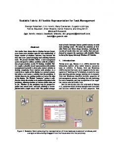
During the last decade, Internet applications have exploded and grown beyond the wildest imaginations. Initial applications were mainly focused on text and graphics contents. With the steady increase in access bandwidth, more and more new applications started using streaming audio and video contents [1], [2]. In response to the increasing demand on streaming video applications over the present best-effort Internet, the coding objective for streaming video has changed to optimizing video quality for a wide range of bit rates rather than a fixed bit rate. The Fine Granularity Scalable (FGS) video coding method adopted in the MPEG-4 standard is just such a technique [3]-[5]. Because of the fine granularity scalability provided by bit-plane coding at the enhancement layer, the FGS scheme can easily adapt to channel bandwidth fluctuations. However, since its motion prediction is always based on the lowest quality base layer, the coding efficiency of the FGS scheme is not as good as, and sometimes worse than, that of the traditional SNR scalable coding [6]. If compared with the non-scalable video coding scheme, the PSNR in the FGS scheme may lose about 3.0dB at the same bit rate [3]. The Progressive Fine Granularity Scalable (PFGS) video coding was proposed in [7], [8] as an improvement over the FGS scheme by allowing multiple references with different qualities for prediction. A typical architecture of the PFGS scheme using two references is depicted in Figure 1, in which each frame at the base layer is always predicted from the previous frame at the base layer (low quality reference), whereas each frame at an enhancement layer is predicted from the previous frame at an enhancement layer (high quality reference). Because the quality of a frame is always higher at an enhancement layer than at the base layer, the PFGS scheme provides more accurate motion compensated prediction than the FGS scheme, thus improving coding efficiency. Just as in the FGS scheme, PFGS generates two bitstreams: the base layer bitstream and the enhancement layer
bitstream. In general, the bit rate of the base layer is low enough to fit in the minimum network bandwidth. Therefore, it is reasonable to assume that the base layer is always available at the decoder. However, since the high quality references comprise part of the DCT coefficients encoded at the enhancement layer, more bandwidth is needed to transmit them to the client. When the channel bandwidth somehow decreases, the decoder may partially or even completely lose the high quality references. In this case, the decoder has to use a reference frame that is not identical, and of possibly lower quality, to the high quality reference used for the motion compensation process of the enhancement layers. The disparity between the high quality references used at the encoder and the decoder will inevitably cause drifting problems in the PFGS scheme. A basic method is first proposed to reduce the drifting errors in the PFGS scheme [8], where the high quality reference is alternatively reconstructed from the previous low quality reference and the previous high quality reference. When the low quality reference is used for reconstruction as indicated by hollow arrows with solid lines in Figure 1, both the encoder and the decoder can always obtain the same temporal prediction. Thus the drifting errors propagated from the previous frames can be eliminated. However, this method also has a negative effect on coding efficiency, since the high quality reference cannot obtain the best quality it could get. Furthermore, since the choice of the temporal references is frame-based, improving coding efficiency at high bit rates and at the same time effectively reducing drifting errors at low bit rates becomes very difficult for the original PFGS scheme. In order to achieve a good trade-off between high coding efficiency and low drifting errors, we investigate a macroblock-based technique to optimize the previous PFGS coding scheme. The basic idea was first introduced in [9], [10]. In this paper, we first analyze the occurrence and propagation of the drifting errors for a single corrupted frame. Then, based on the multiple-frame extension to this simple case, an iterative drifting model is
established at the encoder to simulate drifting errors that could occur at the decoder. Instead of using a single INTER coding mode for the whole enhancement frame that was used in [8], three new INTER modes are introduced for coding the enhancement macroblocks. Similar to the drifting reduction method in [8], one of these modes can effectively reduce drifting errors. Selecting the coding mode at the macroblock level makes the PFGS scheme more flexible in being able to apply several different strategies for drifting reduction instead of only one at the frame level. Moreover, with the estimated information provided by the drifting model, a decision-making mechanism is developed to optimally select the coding mode for each enhancement macroblock, which offers a significant improvement in coding efficiency as well as reducing the drifting errors. The rest of this paper is arranged as follows. Section 2 focuses on analyzing and modeling the drifting errors in the PFGS scheme. An iterative drifting model is eventually established in this section. Section 3 presents the macroblock-based PFGS scheme that provides flexible balance between drifting reduction and coding efficiency improvement. The three new INTER coding modes are also discussed in detail. The decision-making mechanism is proposed in Section 4 to optimally select the coding mode of each macroblock at the enhancement layer. The experimental results given in Section 5 demonstrate the flexibility and efficiency of the proposed techniques. Finally, Section 6 concludes this paper.
2
DRIFTING ERROR ANALYSIS AND MODELING
The error drifting phenomenon is a problem that commonly exists in the transmission of digital video over error-prone channels or when using layered scalable video coding techniques and if the previous reference frames cannot be fully reconstructed. Different approaches have been proposed to reduce or eliminate drifting errors. INTRA refresh techniques [11]-[13] can terminate transmission errors propagated from previous frames by refreshing image regions with INTRA macroblocks. The NEWPRED technique [14]-[15] synchronizes the
references used at the encoder and the decoder in terms of the feedback from the client. In this approach, the receiver side has to transmit an ACK signal or a NACK signal to notify the transmitter side whether or not an image is correctly decoded. The encoder always predicts from those images that are correctly received. For layered scalable video coding, such as PSNR layered coding and spatial layered coding, using several prediction loops [16] is probably the most effective technique for eliminating drifting errors. Several alternative techniques using either an additional correction signal or complex filters during the sampling process are also proposed to reduce the drifting errors for the one prediction loop scheme [17]-[19]. INTRA refresh and the NEWPRED techniques can effectively eliminate drifting errors using the feedback from the receiver. However, for streaming video applications, video bitstreams are normally coded/generated in advance and then stored at the server. The encoder cannot get any feedback from the receiver during the encoding time. There are also proposals that periodically insert INTRA macroblocks in the bitstreams; however, this would severely degrade coding efficiency. The technique using multiple prediction loops is very effective for the traditional layered scalable video coding, but it requires that the enhancement bitstream should be either completely delivered or completely dropped in one Group of Picture (GOP). This means that the references used at the encoder and the decoder are always consistent in the same GOP if there are no errors in the transmission. However, this technique only gives a very coarse scalability at the GOP level. Due to the arbitrary truncation of the enhancement bitstream in the PFGS scheme, effective drifting reduction becomes a very difficult task. Firstly, the PFGS encoder doesn’t know the network conditions at all during the encoding process. The only assumption made is that the network bandwidth is always more than the base layer bit rate, but thus may also fluctuate in a wide range and at variable duration. Secondly, different network conditions mean different truncations to the PFGS enhancement bitstream, which in turn cause different
drifting errors in every frame. This requires that the drifting reduction technique in the PFGS scheme should appropriately attenuate any possible transmitted errors and maintain stable performance at any truncation. As a premise of effective drifting reduction, the PFGS encoder needs to evaluate the transmitted errors as well as their effects. However, it is indeed impossible to accurately calculate the drifting errors at the PFGS encoder without any feedback from the client. Therefore, this paper first focuses on finding out an appropriate technique for drifting estimation at the encoder. The following analysis has partially been published in [20]. Figure 2 is a block diagram of the PFGS encoder, for the purpose of analyzing drifting errors, in which the enhancement layer is predicted and reconstructed always from the high quality reference. Furthermore, the motion estimation module is omitted for simplicity in this diagram. The motion estimation is performed between the current and previous original images, namely is independent of the reconstructions. The motion vectors obtained are used in both of the motion compensation modules in Figure 2. Since there are two references in the PFGS encoder, this produces two sets of predicted DCT coefficients, a first set of predicted DCT coefficients which are the prediction errors formed by referencing the previous low quality reference, and a second set of coefficients which are the prediction errors formed by referencing the previous high quality reference. For convenience, we specify that a lowercase character denotes an image in the pixel domain, and an uppercase character denotes an image in the DCT domain. The subscript “b” and “e” indicate the base layer and the enhancement layer respectively. The hat “~” marker above a character denotes the reconstructed image and DCT coefficients at the encoder. The hat “^” marker above a character denotes the decoded image and DCT coefficients. Thus, according to the foregoing convention, the first predicted residual image is xb in Figure 2,
and the corresponding DCT coefficients X b are encoded at the base layer. The second predicted residual
~
image is xe , and the differences between X e and the reconstructed X b generate the enhancement bitstream with the bit plane coding technique. The number of bit planes encoded at the enhancement layer is not fixed, but based on the number of bits needed to represent the maximum residues in binary format. All bit planes are divided into two layers: the low enhancement layer and the high enhancement layer. Only bit planes in the low enhancement layer are used to reconstruct the high quality references. In general, there are 1~3 bit planes in the low enhancement layer dependent on the given bit rate for the high quality references. Since the reconstructed high quality references always consist of DCT coefficients encoded at the low enhancement layer, if this layer is partially or even completely dropped during transmission, the high quality references obtained at the decoder would differ from the ones used at the encoder. This in turn would lead to drifting errors. In the following section, we will analyze the occurrence and propagation of drifting errors when a single low enhancement layer gets corrupted, and then extend the analysis to the case of multiple corrupted low enhancement layers.
2.1
Corrupted low enhancement layer in a single frame
Firstly, let’s assume that there are N frames in a GOP, and only the first frame in each GOP is encoded as an I frame. Using the inverse DCT transform on the joint reconstructed DCT coefficients of the base layer and the low enhancement layer we can generate the high quality reference in an I frame. If part of the low enhancement layer is corrupted during transmission, the difference between the high quality references used at the encoder and the decoder can be described as
~ e(n) = DCT −1 ( X l (n) − Xˆ l(n)) . −1
(1)
Here n is the counter of frame (n = 0 for I frames), and DCT () denotes the inverse DCT transform.
X l (n) denotes DCT coefficients encoded at the lower enhancement layer. When the whole lower enhancement layer is correctly transmitted to the client, e(n ) should be zero. In the worst case, the lower −1
~
enhancement layer is completely dropped and e(n ) would be equal to DCT ( X l ( n)) . Similarly, for an Inter predicted frame, the high quality references are reconstructed at the decoder and the encoder using the following formulas
rˆe (n) = pˆ e (n) + DCT −1 ( Xˆ b (n) + Xˆ l (n)) ,
(2)
~ ~ ~ re (n) = ~ pe (n) + DCT −1 ( X b (n) + X l (n)) ,
(3)
where re (n) and pe (n) denote the high quality reference and the motion prediction image from the previous high quality reference, respectively. In this section, we only consider that the lower enhancement layer of the frame n is corrupted in the entire GOP. Then, for this frame pˆ e ( n) is equal to ~ pe (n) and Xˆ b (n) is
~
equal to X b ( n) , and by subtracting (2) from (3), we get the same result as in (1). Due to the second motion prediction loop used in the PFGS scheme, the high quality reference forms the next frame prediction through motion compensation, i.e.,
⎧ pˆ e (n + 1) = MCn+1 (rˆ e (n)) . ⎨~ ~ ⎩ pe (n + 1) = MCn+1 (r e (n))
(4)
Here MC () denotes the motion compensation. The subscript “n+1” indicates that the motion vectors of the (n+1)th frame are used in this motion compensation. Even though the lower enhancement layer in this frame is correctly delivered to the client, the decoded high quality reference still contains quality losses due to the corrupted prediction from the previous frame. The error propagated from the nth frame can be represented as
y (n + 1) = ~ pe (n + 1) − pˆ e (n + 1) ~ ~ = MCn+1 ( ~ pe (n) + DCT −1 ( X b (n) + X l (n))) − MCn+1 ( pˆ e (n) + DCT −1 ( Xˆ b (n) + Xˆ l (n))) . (5)
Since motion data is encoded in the base layer, we assume that the decoder can get the same motion vectors and motion modes as in the encoder. With the same motion data, the sum of each signal after motion compensation is equal to the motion compensation of the sum of two signals. Therefore, (5) can be simplified to
~ y (n + 1) = MCn+1 ( DCT −1 ( X l (n) − Xˆ l (n))) .
(6)
where y ( n + 1) is the error propagated from the nth frame to the (n+1)th frame. Moreover, the error is also propagated to other following frames in this GOP through motion compensation. By extending (6), the error propagation from the nth frame to the (n+k)th is described as
~ yn ( n + k ) = MCn+k (...( MCn+1 ( DCT −1 ( X l (n) − Xˆ l ( n))))) .
(7)
The above formula exhibits the occurrence and propagation of drifting error when a single lower enhancement −1 ~ layer is corrupted during transmission. DCT ( X l (n) − Xˆ l (n)) is the error image due to the transmitted
errors in the nth frame. Within the same GOP, the errors are propagated to the (n+k)
th
frame through k
successive motion compensations.
2.2
Corrupted lower enhancement layer in multiple frames
When streaming video over the Internet, the burst decrease of channel bandwidth or network congestion usually corrupts the lower enhancement layers in multiple frames instead of only in a single frame. The general case is that the lower enhancement layer of each frame may be corrupted during transmission. From (7), we know that errors occurring in a single frame can be propagated within one GOP. Therefore, the drifting errors that appeared in the nth frame are the accumulated propagation from errors in all previous frames, i.e.,
y (n ) =
n −1
∑
yk (n ) .
(8)
k =0
Here yk (n) denotes the error propagation from the kth frame to the current frame. By incorporating (7) and (1)
into (8), we can get n −1
y (n ) = ∑ MC n (...( MC k +1 (e( k )))) .
(9)
k =0
Here e(k ) denotes the error image that was generated at the lower enhancement layer in the kth frame. This clearly explains why the drifting errors can rapidly deteriorate the quality of the decoded video. If though (9) is directly used to calculate the drifting errors at the encoder, the computational complexity would be very high. In (9), the error image that was generated in each of the previous frames is first warped to the current frame through one or multiple motion compensation operations and is then accumulated. In other words, the same motion compensation is performed multiple times to propagate each error image from one frame to the next. Since the same motion vectors are used in this process, all errors from the previous frames can be first added together and then propagated to the next frame through only one motion compensation. Therefore, an iterative model is derived from (9)
0 ⎧ y(n) = ⎨ ⎩ MC n ( y ( n − 1) + e( n − 1))
n=0 N ≥n>0
.
(10)
Here N is the total number of frames in one GOP. y (n − 1) is the accumulative error in the (n-1)th frame, and
e ( n − 1) is the new error that occurred at the lower enhancement layer in this frame. With the motion compensation, their sum forms the next drifting error in the nth frame. Utilizing (10) to model drifting errors at the encoder is much simpler compared to (9). The additional complexity is one motion compensation operation and one inverse DCT transform for each frame. Moreover, the extra computation is only necessary at the encoder side for encoding optimization. If the encoder can get feedback about the corrupted DCT coefficients at the lower enhancement layer from the client side, the iterative model can accurately reproduce the drifting errors that have occurred at the decoder. However, since such
feedback isn’t available in streaming video applications, the PFGS scheme can use the iterative model to estimate the drifting errors that may occur in the worst case scenario, i.e., all lower enhancement layers in the first (n-1) frames were completely dropped, and the decoder obtains again the lower enhancement layer in the nth frame. This means that the errors that have occurred in all previous frames have always their maximum value. Therefore, the estimated drifting error ymax (n) in this case is
0 ⎧ ymax (n) = ⎨ −1 ~ ⎩MCn ( ymax (n − 1) + DCT ( X l (n − 1)))
3
n =1 . N ≥ n >1
(11)
MACROBLOCK-BASED DRIFTING REDUCTION
This section develops the drifting reduction technique at the macroblock level. In the original frame-based PFGS, the references for prediction and reconstruction are used as the entire frame in the enhancement layer coding. Since however there are two references that are used in the PFGS scheme, a flexible method for selecting the reference frame to be used at each enhancement macroblock may achieve a better trade-off between drifting error and coding efficiency. Derived from the MPEG-4 FGS and the original PFGS scheme, three new INTER coding modes for enhancement macroblocks are first introduced in Figure 3, namely the LPLR (Low Prediction Low Reconstruction) , HPHR (High Prediction High Reconstruction), and HPLR (High Prediction Low Reconstruction) modes. Gray rectangular boxes in Figure 3 denote those layers to be reconstructed as references. Solid arrows with solid lines are for temporal predictions, hollow arrows with solid lines are for reconstruction of high quality references, and solid arrows with dashed lines are for predictions in the DCT domain.
3.1
Proposed INTER enhancement macroblock modes
In the LPLR mode, the enhancement macroblock is predicted and reconstructed only from the low quality reference. Obviously in this mode there is no drifting error, while if all enhancement macroblocks are encoded with this mode, the PFGS scheme will be exactly the same as the FGS scheme. Generally, the coding efficiency of LPLR mode is very low due to the low quality temporal prediction. In the HPHR mode, the enhancement macroblock is predicted and reconstructed entirely from the high quality reference. The PFGS scheme can provide the highest coding efficiency at high bit rates when all enhancement macroblocks are encoded with this mode. But, if the lower enhancement layers in the previous frames are not available due to network bandwidth or transmission errors, the decoder has to instead use the low quality references. In this case, the reconstructed high quality reference for the next frame at the decoder becomes
rˆe (n) = pˆ b (n ) + DCT −1 ( Xˆ b( n) + Xˆ l( n)) .
(12)
Here pˆ b ( n ) denotes the low quality prediction at the decoder. Compared with the correct high quality reference, the quality loss ∇rˆe (n) in the current frame can be obtained by subtracting the formula (12) from (3), i.e.
~ ∇rˆe (n) = [ ~ pe (n) − pˆ b (n)] + DCT −1 ( X l (n) − Xˆ l (n)) .
(13)
The first item in (13) is the error introduced by using the low quality reference instead of the high quality reference, and the second item is the error that has occurred at the current lower enhancement layer. In general, because of propagation and accumulation of drifting errors, the first item has a major effect in deteriorating the decoded video quality. Regardless of the current errors at the lower enhancement layer, the quality loss is mainly caused by the mismatching temporal prediction
∇rˆe (n) ≈ ~ pe (n) − pˆ b (n) .
(14)
The HPLR mode provides a novel method to reduce the above errors. In this mode, the enhancement macroblock is predicted from the high quality reference, while reconstructed from the low quality reference at both the encoder and the decoder. In other words, the reference used for prediction could differ from that for reconstruction. When the enhancement macroblock is encoded with HPLR mode, the encoder and the decoder can always obtain the same temporal prediction. The potential propagation of the quality losses ∇rˆe (n) is eliminated. Furthermore, HPLR mode also offers more flexibility at the macroblock level than at the frame level. In HPLR mode, since the current high quality reference is reconstructed from the previous low quality reference, the quality losses ∇rˆe (n) in (14) that originally occur between the encoder and the decoder in HPHR mode is now transferred to the reconstructed high quality reference at the encoder. Due to the quality losses in the reconstructed high quality reference, the temporal prediction for the next frame also has the corresponding losses. This means that more bits are needed to encode the predicted residues in the next frame. Therefore, HPLR mode also affects the coding efficiency of the PFGS scheme. However, when the enhancement layer is predicted from the high quality reference, reasonably utilizing the mixture of HPHR mode and HPLR mode should provide a better trade-off between high coding efficiency and low drifting errors.
3.2
Macroblock-based PFGS decoder
Figure 4 shows the macroblock-based PFGS decoder and how the different INTER modes are considered in the decoding process. First of all, there are two reference frames in this decoder. The first one is located in the Base Layer decoder and stored in Frame Buffer 0, and is of low quality, while the second one is located in the Enhancement Layer decoder and stored in Frame Buffer, and is of high quality. Only the low quality reference is allowed in the reconstruction of the base layer in order to assure the no drifting error exists at this layer. The
base layer decoder is the same as that of the baseline FGS, and can be compatible to other standards, such as MPEG-2 and H.263. In fact, the base layer can also use the new JVT standard as is also shown in [21]. This will further improve the coding efficiency of PFGS due to JVT being a higher efficient codec. The enhancement layer can use the two different quality references for reconstruction. The enhancement bitstream is first decoded using bit-plane Variable Length Decoding (VLD) and mode VLD. The bit planes at the enhancement layer are categorized into a lower enhancement layer and a higher enhancement layer. Only the bit planes at the lower enhancement layer are used to reconstruct the high quality reference. In Figure 4, n(t) is the number of bit planes at the lower enhancement layer, and m(t) is the number of additional bit planes for the reconstruction of the display frame. The decoded block-based bit planes are used to reconstruct the DCT coefficients of the lower and higher enhancement layers using the Bit-Plane Shift modules. After the inverse DCT, the lower enhancement DCT coefficients plus the reconstructed base DCT coefficients generate the error image for reference, and all DCT coefficients including the higher enhancement layer generate the error image for display. Furthermore, there are two switches S1 and S2 at the PFGS decoder that control which temporal prediction is used at each enhancement macroblock. The decoded macroblock mode decides the actions of the two switches. When the coding mode of one macroblock is LPLR, the switches S1 and S2 connect to the low quality prediction. When the coding mode is HPHR, both of the switch S1 and the switch S2 connect to the high quality prediction. When the coding mode is HPLR, the switch S1 connects to the low quality prediction. However, the switch S2 still connects to the high quality prediction. Since the display frame does not cause any error propagation, the display frame is always reconstructed from the high quality prediction in the HPLR mode. More coding modes can be readily defined with the proposed macroblock-based technique as long as they have
the virtue of improving coding efficiency or reducing error propagation. For example, [22] and [23] suggest generating a new reference using the average of the low quality reference and the high quality reference. All layers are predicted and reconstructed from the generated reference. In addition, Leaky prediction is another good technique for reducing drifting errors [24]. The basic principle is to gracefully decay the enhancement information introduced in the prediction loop so as to limit the error propagation and accumulation. This technique can control the drifting errors in the given range. Some scalable coding schemes with this technique show very promising results in achieving a better trade-off between low drifting errors and high coding efficiency [25][26].
4
DECISION MECHANISM FOR MACROBLOCK CODING
The purpose of the decision-making mechanism is for selecting the proper mode of each enhancement macroblock. Besides the three INTER modes mentioned in the previous section, INTRA mode is also allowed in the enhancement layer coding. Whether INTRA or INTER mode is to be used is determined by the motion estimation module at the base layer. If a macroblock at the base layer is encoded in INTRA mode, the corresponding enhancement macroblock is also encoded using INTRA mode; otherwise the proposed decision-making mechanism has to determine which INTER coding mode is more suitable for this enhancement macroblock. As illustrated in Figure 5, the HPHR and the LPLR curves denote all enhancement macroblocks encoded with HPHR mode and LPLR mode, respectively. At low bit rates, the decoded quality indicated by the HPHR curve is far lower than that indicated by the LPLR curve because of the drifting errors. While channel bandwidth increases, the decoded quality of the HPHR curve increases rapidly. At high bit rates, the HPHR curve will be close to that of the single layer video coding. The decision-making mechanism is expected to reduce the
drifting errors at low bit rates and maintain the high coding efficiency at high bit rates by optimally selecting the INTER coding mode for each enhancement macroblock. The decision-making mechanism first determines whether one macroblock should be encoded with LPLR mode or not. The reference for prediction in the LPLR mode is of low quality, but the reference used in the HPHR and HPLR modes is of high quality. Therefore, the criterion to distinguish the LPLR mode from the other two modes is defined as
~ ~ min( X b − X b , X e − X b ) . L
The distance function
L
(15)
L
is usually the Mean Square Distance (L=2), or the Mean Absolute Distance (L=1).
When the enhancement layer is predicted from the low quality reference, the DCT residues encoded at the
~
~
enhancement layer are X b − X b , otherwise the encoded DCT residues are X e − X b . If the metric error of the first item in (15) is less than that of the second item, this macroblock is encoded in LPLR mode. Since most of enhancement macroblock use the high quality reference for prediction, the key point in the decision-making mechanism is how to determine which mode (HPHR or HPLR) the remaining macroblocks will be coded in. In fact, the decision-making mechanism is expected to achieve the performance of the Trade-off curve that is shown in Figure 5. If the LPLR curve is used as reference in the decision-making mechanism, the criterion for selecting the coding mode between HPHR mode and HPLR mode is defined as t3
t2
mode∈{HPHR,HPLR} t 2
t1
arg max
( ∫ s (t ) − sLPLR (t ) L dt − λ ∫ sLPLR (t ) − s (t ) L dt ) .
(16)
where s (t ) is the PSNR curve obtained by optimal mode decision, and sLPLR (t ) is the corresponding PSNR curve when all macroblocks are encoded with the LPLR mode.
λ is the weighting factor. The first item in (16)
denotes the coding efficiency gains at high bit rates, and the second item denotes the quality losses at low bit
rates. Obviously, the criterion (16) will result in rather intensive computation in a real application. Thus, the proposed decision-making mechanism first simplifies the criterion to only constrain the drifting errors at low bit rates by using the least number of macroblocks encoded with HPLR mode. Moreover, in order to further reduce the computation, the maximum quality losses at low bit rates are used to replace the integral. From the iterative drifting model, we already know that the maximum quality losses are caused by the worst case drifting errors. Therefore, the new criterion is defined as
ymax (n) L ≥ k x(n) − ~ rLPLR (n) L ,
(17)
where x (n) is the nth original image. The left side of equation (17) is the worst case drifting errors propagated from the previous frames. The right side of equation (17) is the given threshold for the allowable quality losses at low bit rates. ~ rLPLR (n) is the reconstructed high quality reference with the LPLR method. The factor k is an adjustable parameter to provide the balance between drifting errors and coding efficiency. In other words, if the drifting errors at the current macroblock are larger than the allowable quality losses, this macroblock is encoded with HPLR mode to reduce the drifting errors; otherwise this macroblock is encoded with HPHR mode to achieve higher coding efficiency. From the simplified iterative model given in (10), the encoder still needs to perform an additional motion compensation for estimating drifting errors. A simple method for selecting the coding mode only based on the estimated worst case drifting errors is further investigated in this section. In the worst case, the drifting errors are formed by all DCT coefficients at the entire lower enhancement layer through propagation and accumulation as shown in (11). Besides calculating the drifting errors, the iterative model essentially provides a simple form of describing the present predictive transform coding system. Its inputs are the encoded DCT
coefficients from the previous I frame to the current frame, and the corresponding output is the current reconstructed image after DCT transform and motion compensation. Since the low quality reference is reconstructed only by the DCT coefficients encoded at the base layer, it can be similarly described as
0 ⎧ ~ pb (n) = ⎨ −1 ~ ~ ⎩MCn ( pb (n − 1) + DCT ( X b (n − 1)))
n =1 . N ≥ n >1
(18)
However, the high quality reference is derived from the DCT coefficients encoded at not only the base layer but also at the lower enhancement layer. Fortunately, only a single motion estimation is used in the PFGS scheme, and the obtained motion vectors equally affect both the base and enhancement layers. With the same motion data and linear inverse DCT transform, the high quality reference can be represented by adding (11) and (18) together
~ pe (n) = ~ pb (n) + ymax (n) .1
(19)
In other words, the drifting errors in the worst case are equal to the differences between the high quality reference and the low quality reference. Therefore, the criterion (17) for mode decision between HPHR mode and HPLR mode can be rewritten as
~ pe (n) − ~ pb (n) L > k x(n) − ~ rLPLR (n) L . x ( n) − ~ rLPLR (n)
L
(20)
aims to provide an approximate threshold to constrain the drifting errors at low bit rates.
Using ~ rLPLR ( n ) still needs the extra reconstruction of the high quality reference with the LPLR method. The high quality prediction ~ pe (n) can be viewed as the approximation of the reconstructed image. Adjusting parameter k will also have a similar effect as the threshold. Therefore, in the proposed PFGS scheme, the high quality reference ~ pe (n) takes the place of ~ rLPLR ( n ) ,
1
Here, the effects of clipping and computational precision are not taken into account.
~ pe (n) − ~ pb (n) > k ' x(n) − ~ pe (n) .
(21)
Here k ' is the parameter after adjustment. Since the two different quality predictions ~ pe (n) and ~ pb (n) are already available, no extra computation is introduced to the PFGS encoder. The coding mode information of each macroblock is encoded in the macroblock header. Since the base layer bitstream already provides the information about the INTRA mode, only the INTER mode information needs to be encoded in the enhancement bitstream. A simple VLC table is used to compress them into the enhancement bitstream.
5
EXPERIMENTS AND ANALYSIS
Extensive experiments and simulations are designed to verify the proposed drifting reduction and macroblock-based control techniques in this section. The coding efficiency of PFGS scheme is compared with FGS scheme and the non-scalable coding scheme in MPEG-4. All test conditions are derived from those specified in the MPEG-4 core experiments [27]. The CIF sequences Foreman (300 frames), Coastguard (300 frames), Carphone (250 frames) and News (300 frames) are used in this experiment. Only the first frame is encoded as an I frame, and all other frames are encoded as P frames. The base layer is encoded with a predictive transform codec, which can be compatible to the existing video coding standards, such as H.263, MPEG-2, MPEG-4, or even JVT. This experiment uses the MPEG-4 baseline codec. A simple half-pixel motion estimation scheme using linear interpolation was implemented to extract the motion vectors between video frames. The motion vector range is set to ±31.5 pixels. The same motion vectors are applied to two motion compensation modules, which in turn produce the two predicted images. The base layer is encoded at a fixed bitrate of 128 kbps using the TM5 rate control, and the coding frame rate is 10Hz. The bit rate of the enhancement layer is not constrained. Since the enhancement layer produces an
embedded bitstream, the streaming server can truncate it at any place to match the given channel bandwidth. The truncating procedure is independent of the decoder. In our experiments, the enhancement layer bitstream is truncated at 128 kbps, 256 kbps, …, up to 768 kbps with an interval of 128 kbps. The first experiment is to verify the performance of the proposed macroblock-based drifting reduction technique at low bit rates. Three fine granularity scalable video coding schemes are used in this experiment, i.e., the FGS scheme, the PFGS scheme without drifting reduction, and the PFGS scheme with optimal mode decision. For the PFGS scheme, the lower enhancement layer may comprise of two or three bit planes dependent on its generated bits. We specify that the generated bits at the lower enhancement layer of each frame are at least 20 kbits in this experiment. Since the generated bits in each bit plane vary in a wide range, the actual bit rate of the high quality reference as shown in Table 1 is far larger than 200 kbps. Our simulation assumes that the available network bandwidth is only 256 kbps. Besides the guarantee of the base layer, only 128 kbps of the enhancement bitstream is available at the decoder. Therefore, the lower enhancement layer is always partially transmitted to the decoder. The parameter k in (21) is fixed to 1.8 for each sequence, and the absolute mean distance is used in this experiment for mode decision. With the proposed mode-decision mechanism, the average percentage of INTRA mode and each INTER mode in the predicted frame is given in Table 1. Most of the enhancement macroblocks are encoded with HPHR mode, and about 10% of the macroblocks are encoded with HPLR mode for drifting reduction. The rest of the macroblocks are encoded with INTRA or LPLR mode. The experimental results are depicted in Figure 6. “PFGS” in Figure 6 denotes the PFGS scheme without drifting reduction, and “PFGS dr” denotes the PFGS scheme with optimal mode decision. Since the FGS scheme always uses the reconstructed base layer as reference, we can think that the FGS curve is the decoded
quality without any drifting errors. For the PFGS scheme without drifting reduction, the maximum quality loss caused by the drifting errors in a single frame is about 2.0 dB for Foreman Y, Coastguard Y and Carphone Y. The maximum quality loss even exceeds 3.0 dB in News sequence. Furthermore, the PSNR curves are obviously drifting toward the low end when the frame number is increasing. In the PFGS scheme with the proposed drifting reduction technique, although only about 10% macroblocks are encoded with HPLR mode, the drifting errors are almost completely eliminated. Compared with the PSNR curve of the FGS scheme, the PFGS scheme with drifting reduction can achieve almost the same performance in both terms of average PSNR and single frame PSNR. There is no obvious drifting phenomenon. The second experiment is to examine the average coding efficiency of the PFGS scheme with the proposed techniques at bit rates varying from 128 kbps to 768 kbps. This is also compared with the FGS scheme and the non-scalable video coding scheme. Two different PFGS schemes are used in this experiment, the frame-based PFGS scheme proposed in [8], where the high quality reference in every two frames is reconstructed from the previous base layer, and the PFGS scheme with the proposed macroblock-based control. All experimental conditions and parameters are the same as the ones used in the first experiment. The TM5 rate control was used in both the non-scalable video encoder and for encoding the base layer. The enhancement bit rate is evenly allocated to each frame in all schemes. The experimental results are given in Figure 7. “Single” in Figure 7 denotes the non-scalable video coding, and “PFGS frame” denotes the frame-based PFGS scheme. The PSNR gap between the FGS scheme and the non-scalable video coding is about 2.0~3.0 dB at bit rates from 256 kbps to 896 kbps. Although the FGS scheme can provide some highly desirable and useful properties, such as fine granularity scalability, channel bandwidth adaptation and error recovery, this cost still seems to be too expensive. At low bit rates, the PFGS
scheme with the proposed drifting reduction has almost the same performance as the FGS scheme. The reason is that the current enhancement bit rate is not enough to deliver the lower enhancement layer to the decoder. However, while the bit rate increases, the coding efficiency of the macroblock-based PFGS scheme with drifting reduction also increases rapidly. Since the bit rate of the high quality reference is high in the Foreman and Coastguard sequences, they get the maximum coding efficiency gain at 768 kbps and at 640 kbps, respectively. The Carphone and News sequenes can get the maximum coding efficiency gain at 512 kbps. Compared with the FGS scheme, the macroblock-based PFGS with drifting reduction can get about 1.6 dB gain in the Foreman, Coastguard and Carphone sequences, and even reach 2.3dB gain in the News sequence. Even compared with the frame-based PFGS scheme, the proposed techniques can help the PFGS scheme to improve coding efficiency up to 0.7dB in the first three sequences, as well as up to 1.6dB in the News sequence. Therefore, we conclude that the drifting reduction and the macroblock-based control techniques can significantly improve the coding efficiency of the PFGS scheme.
6
CONCLUSIONS
This paper firstly analyzes the occurrence and propagation of drifting errors in the PFGS scheme. As a result, an iterative drifting model is established to simulate the drifting errors at the encoder. In order to flexibly and effectively control the PFGS coding, three INTER modes are proposed for the enhancement macroblock. Furthermore, a decision-making mechanism is investigated for optimally selecting the coding mode for each macroblock, which can achieve a better trade-off between high coding efficiency and low drifting errors. With these proposed techniques, the coding efficiency of the PFGS scheme is up to 2.3dB higher than that of the FGS scheme, as well as up to 1.6dB higher than that of the frame-based PFGS scheme. Meanwhile, the drifting
errors occurred at low bit rates are almost completely eliminated. Furthermore, with the proposed techniques the coding efficiency gap between PFGS scheme and the non-scalable video coding is below 1.0dB at moderate or high bit rates. Since the coding efficiency provided by the non-scalable scheme is an ideal and unattainable goal for fine-grain scalable coding schemes, a coding efficiency loss of 1.0dB can be considered as a reasonable expense for getting many important properties, such as fine granularity scalability, channel adaptation and error recovery. Therefore, we could confidently conclude that the macroblock-based PFGS provides a strong competitive scheme for the developing video streaming applications. Apart from coding efficiency, there are still some other problems that need further study for the PFGS scheme and its applications. Firstly, the proposed macroblock-based PFGS only supports image quality or bit rate scalability. Facing the current heterogeneous Internet and the various kinds of PC and non-PC devices, high degree of variation can never be solved by one scalability mode alone. Combinations of spatial, temporal and SNR scalability with fine granularity would serve a broad range of data rates on the networks or a wide selection of terminals with different characteristics. Although the proposed PFGS provides the potential capability to implement such universal scalability, some key techniques still need to be further investigated. Secondly, the PFGS scheme covers the entire bit rates from the base layer up to even lossless coding using the single enhancement bitstream. Since only one high quality reference is used for the prediction at the enhancement layer, the PFGS scheme can provide high coding efficiency limited within a certain range after the high quality reference is available. However, the current dominant video streaming players, such as Real Player and Window Media Player, usually own multiple bitstreams with different bit rates at the server to adapt to different speed connections. A similar technique can also be used in the PFGS scheme by using multiple base
layer and enhancement layer bitstreams to provide better coding efficiency at the entire bit rate range, provided that the server could smoothly and flexibly switch among multiple PFGS bitstreams. Finally, the process of delivering reliably and effectively a PFGS bitstream over the current best-effort Internet is another important issue. It involves many key problems such as how to estimate the current available channel bandwidth through packet loss ratio and round trip time, how to truncate and packetize the PFGS bitstream to fit the estimated channel situation with rate-distortion optimality, how to better protect the base layer and the lower enhancement layer information with FEC and ARQ techniques, and so on.
ACKNOWLEDGMENT The authors would like to thank Dr. Guobin Shen and Alexis M. Tourapis for many valuable discussions and suggestions. The authors also thank Dr. Weiping Li for many beneficial discussions, encouragements, and helps on the PFGS framework.
Reference [1] A. Luthra, Need for simple streaming video profile, ISO/IEC JTC1/SC29/WG11, MPEG doc M5800, Noordwijkerhout, Netherlands, March 2000. [2] J. Lu, Signal processing for Internet video streaming: A review, SPIE in Image and Video Communication and Processing 2000, vol. 3974, pp 246-258, 2000. [3] W. Li, Fine granularity scalability in MPEG-4 for streaming video, ISCAS 2000, vol. 1, pp 299-302, Geneva, Switzerland, 2000. [4] W. Li, Streaming video profile in MPEG-4, IEEE trans. Circuit and systems for video technology, special issue on streaming video, vol. 11, no 3, pp 301-317, 2001. [5] M. Schaar and H. Radha, A hybrid temporal-SNR fine-granular scalability for Internet Video, IEEE trans.
Circuit and systems for video technology, special issue on streaming video, vol. 11, no 3, pp 318-331, 2001. [6] J. Arnold, M. Frater and Y. Wang, Efficient drift-free signal-to-noise ratio scalability, IEEE trans. Circuit and systems for video technology, vol. 10, no 1, pp 70-82, 2000. [7] F. Wu, S. Li and Y.-Q. Zhang, DCT-prediction based progressive fine granularity scalability coding, ICIP 2000, Vancouver, Canada, vol. 3, pp 556-559. [8] F. Wu, S. Li and Y. -Q. Zhang, A framework for efficient progressive fine granularity scalable video coding, IEEE trans. Circuit and systems for video technology, special issue on streaming video, vol. 11, no 3, pp 332-344, 2001. [9] X. Sun, F. Wu, S. Li, W. Gao and Y,-Q. Zhang, Macroblock-based progressive fine granularity scalable video coding, ICME2001, Japan, pp 461-464. [10] X. Sun, F. Wu, S. Li, W. Gao and Y-Q. Zhang, Macroblock-based temporal-SNR progressive fine granularity scalable video coding, ICIP2001, Greece, pp 1025-1028. [11] P. Chang and T. Lee, Precise and fast error tracking for error-resilient transmission of H.263 video, IEEE trans. Circuit and systems for video technology, vol. 10, no 4, pp 600-607, 2000. [12] J. Liao and J. Villasenor, Adaptive intra block update for robust transmission of H.263, IEEE trans. Circuit and systems for video technology, vol. 10, no 1, pp 30-35, 2000. [13] E. Steinbach, N. Farber and B. Girod, Standard compatible extension of H.263 for robust video transmission in mobile environments, IEEE trans. Circuit and systems for video technology, vol. 7, no 6, pp 872-881, 1997. [14] I. Rhee and S. Joshi, Error recovery for interactive video transmission over the Internet, IEEE Journal of
selected areas in communications, vol. 18, no 6, pp 1033-1049, 2000. [15] H. Kimata, Y. Tomita, H. Yamaguchi and S. Ichinose, Study on adaptive reference picture selection coding scheme for the NEWPRED, Global Telecommunications Conference, vol. 3, pp 1431-1436, 1998. [16] C. Herpel and H. Hepper, Multiple loop decoder for TM1 scalable mode, ISO/IEC JTC1/SC29/WG11, MPEG92, doc 288, 1992. [17] R. Mathew and J. Arnold, Layer coding using bitstream decomposition with drift correction, IEEE trans. Circuit and systems for video technology, vol. 7, no 6, pp 882-891, 1997. [18] O. Werner, Drift analysis and drift reduction for multi-resolution hybrid video coding, Signal Processing: Image communication, vol. 8, pp 387-409, 1996. [19] B. Girod, N. Farber, and U. Horn, Scalable codec architectures for Internet video on demand, in Proc. 1997 Asilomar Conf. Signals and Systems, Pacific Grove, CA, 1997. [20] F. Wu, S. Li, B. Zeng and Y.-Q. Zhang, Drifting Reduction in Progressive Fine Granular Scalable Video Coding, Picture Coding Symposium (PCS2001), Seoul. [21] Y. He, F. Wu, S. Li, Y. Zhong and S. Yang, H.26L-based fine granularity scalable video coding, ISCAS 2002, Phoenix, USA, vol. 4, pp 548-551. [22] W. Peng and Y. Chen, Mode-adaptive Fine Granularity Scalability, ICIP 2001, Greece, pp 993-996. [23] A. Reibman, L. Bottou and A. Basso, DCT-based scalable video coding with drift, ICIP 2001, Greece, pp 989-992. [24] M. Ghanbari and V. Seferidis, Efficient H.261-based two-layer video codecs for ATM networks, IEEE trans. CSVT, vol. 5, no 2, 171-175, 1995. [25] S. Han and B. Girod, “SNR scalable coding with leaky prediction”, ITU-T Q.6/SG16, VCEG-N53, Santa
Barbara, USA, 2001. [26] H. Huang, C. Wang and T. Chiang, A robust fine granularity scalability using trellis-based predictive leak, IEEE trans. Circuits and Systems for Video Technology, vol. 12, no. 6, 372-385, 2002. [27] MPEG-4 video group, Description of Experiments in FGS, ISO/IEC JTC1/SC29/WG11, MPEG doc N3316, Noordwijkerhout, Netherlands, March 2000.
Tables Table 1: The experimental parameters relative to the PFGS scheme and mode percentages determined by the proposed mode-decision mechanism.
Sequence
Bit rate of the high
Parameter
INTRA
LPLR
HPHR
HPLR
quality reference (kbits/s)
k
(%)
(%)
(%)
(%)
Foreman
465.0
1.8
2.0
9.2
77.9
10.9
Coastguard
485.9
1.8
0.3
12.4
80.8
6.5
Carphone
365.6
1.8
1.0
11.5
78.6
8.9
Table tennis
380.4
1.8
0.2
15.2
70.9
13.7
List of Figure Captions Figure 1: The architecture of the PFGS scheme. Figure 2: The block diagram of the PFGS encoder. Figure 3: The INTER modes for the enhancement macroblock coding. Figure 4: The macroblock-based PFGS decoder. Figure 5: The PFGS scheme with different coding controls. Figure 6: the curves of PSNR versus frame number at enhancement bit rate 128kbits/s. (a) Foreman Y, (b) Coastguard Y, (c) Carphone Y, and (d) News Y. Figure 7: PSNR versus bit rate comparison among FGS, PFGS and non-scalable coding. (a) Foreman Y, (b) Coastguard Y, (c) Carphone Y, and (d) News Y.
B ASE L AYER 1ST ENHANCEMENT LAYER
2ND ENHANCEM ENT L AYER
3RD ENHANCEM ENT L AYER 4TH ENHANCEM ENT L AYER
1
2
3 FRAM ES
4
5
Figure 1: The architecture of the PFGS scheme. (Gray rectangles denote those layers to be reconstructed as references; Solid arrows with solid lines between two adjacent frames are for temporal prediction, Solid arrows with dashed lines are for prediction in the transform domain, and hollow arrows with solid lines are for reconstruction of high quality reference from the previous base layer)
Base Layer Reference
MC
~ rb
~ xb
+
IDCT Base Layer Bitstream
VLC
~ pb
-
+
DCT
xb
x
Q b-1
Qb
Xb
Reconstructed
~ Xb
VLC
Original Image
Xb
Lower Enhancement Layer Bitstream
-
+ xe
+ ~ pe MC
DCT
Ql
Q l-1
Xe
~ Xl
Reconstructed Lower Layer X
+
e
-
+
~ xe
IDCT
~ re
VLC
Higher Enhancement Layer Bitstream
Enhanced Layer Reference
+
Qh
Q h-1
~ Xh
+
Figure 2: The block diagram of the PFGS encoder.
Reconstructed Higher Layer X
e
L ow q u ality ref ere n c e
H ig h q u ality ref ere n c e
L P L R m od e
H P H R m od e
H P L R m od e
Figure 3: The INTER modes for the enhancement macroblock coding.
B IT -P LANE S HIFT
+
+
IDCT
C LIPPING Video S2
Enhancement m(t) Bitstream B IT -P LANE VLD
F RAM E B UFFER 1
MC
n(t)
MVs
B IT -P LANE S HIFT
+
+
IDCT
C LIPPING Video (optional)
S1
M ODE VLD
Base Layer Bitstream
V L D
Enhancement Layer Decoder
Q -1
+
IDCT
MVs
C LIPPING
Video (optional)
MC
F RAM E B UFFER 0
Figure 4: The macroblock-based PFGS decoder.
Base Layer Decoder
Figure 5: The PFGS scheme with different coding controls.
32
36 35
FGS PFGS dr PFGS
34 33
FGS PFGS dr PFGS
31 30
32
29
31 30
28
29 28
27
27
26
26 1
9
17 25 33 41 49 57 65 73 81 89 97
1
9
17 25 33 41 49 57 65 73 81 89 97
(a)
(b)
39 38 37 36
37 FGS PFGS dr PFGS
36.5 36
35
35.5
34
35
33
34.5
32
FGS PFGS dr PFGS
34
31
33.5
30 29
33 1 6 11 16 21 26 31 36 41 46 51 56 61 66 71 76 81
1
10
19
28
37
46
55
64
73
82
(c) (d) Figure 6: The curves of PSNR versus frame number at enhancement bit rate 128kbits/s. (a) Foreman Y, (b) Coastguard Y, (c) Carphone Y, and (d) News Y.
91 100
40
36
39
35
38
34
37
33
36
32
35
31
34
Single
33
FGS
30
FGS
32
PFGS frame
29
PFGS frame
31
PFGS
28
PFGS dr
30
Single
27 128
256
384
512
640
768
128
896
256
384
(a)
512
640
768
896
(b)
42
44
41
43
40
42
39
41 40
38
39
37
Single
38
Single
36
FGS
37
FGS
35
PFGS frame
36
PFGS frame
34
PFGS dr
35
PFGS
33
34 128
256
384
512
640
768
896
128
256
384
512
640
768
896
(c) (d) Figure 7: PSNR versus bit rate comparison among FGS, PFGS and non-scalable coding. (a) Foreman Y, (b) Coastguard Y, (c) Carphone Y, and (d) News Y.