consistent documentation of business requirements, functional specifications, application architecture, code artifacts, as well as infrastructure and deployment ...
MADCAT A Methodology for Architecture and Deployment of Cloud Application Topologies Christian Inzinger, Stefan Nastic, Sanjin Sehic, Michael Vögler, Fei Li, and Schahram Dustdar Distributed Systems Group, Vienna University of Technology Argentinierstraße 8/184-1, 1040 Vienna, Austria {lastname}@dsg.tuwien.ac.at http://dsg.tuwien.ac.at/ Abstract—The cloud computing paradigm introduces new possibilities and challenges for application design and deployment. On-demand resource provisioning, as well as resource and cost elasticity, need to be considered when realizing largescale distributed applications for cloud environments. Current approaches do not sufficiently address the challenges of efficiently architecting and deploying cloud applications in a holistic manner and do not deal with the specific challenges encountered in cloud infrastructures. In this paper we introduce a methodology tackling the practical problems encountered when designing and deploying cloud applications. It enables the structured creation of cloud-native applications, addressing the complete application development lifecycle, from architectural design to concrete deployment topologies provisioned and executed on cloud infrastructure. By using iterative refinement and seamless provenance documentation of decisions made in the process, the methodology eases communication with relevant stakeholders and enables efficient design and deployment of distributed cloud applications.
I.
I NTRODUCTION
Creating large distributed systems is a complex task involving numerous steps that need to be properly aligned to handle complex resulting application architectures. Due to the high number of involved stakeholders, it is imperative to maintain consistent documentation of business requirements, functional specifications, application architecture, code artifacts, as well as infrastructure and deployment models. Furthermore, different stakeholders expect documentation in varying levels of detail and abstraction that needs to be kept aligned with the application under development. In recent years, cloud computing [1] emerged as a popular approach to host large-scale distributed applications, as opposed to purchasing, provisioning and maintaining a dedicated infrastructure. The utility-driven, on-demand nature of cloud offerings allows customers to easily and quickly provision the exact type and amount of resources needed for a given task. While it enables new possibilities for application design and management, it also introduces challenges not previously encountered in traditional application design and development. Elasticity, one of the fundamental properties of cloud computing, allows for applications to respond to varying load patterns by adjusting the amount of provisioned resources to exactly match their current need, thus minimizing overprovisioning and reducing hosting costs. In addition to resource
elasticity, the cloud computing paradigm enables additional elasticity dimensions, such as cost elasticity and quality elasticity [2]. However, application architects need to explicitly incorporate elasticity concerns in application design to take advantage of the benefits it offers. Components suitable for elastic deployment need to be identified and properly modeled to support a varying number of deployed instances. Although current research does address the issues of modeling [3] and monitoring [4] of elasticity properties, architects still lack a structured methodology to properly integrate elasticity requirements in application architectures, and need to resort to published best practices (e.g., [5]) and reference architectures (e.g., Amazon AWS Reference Architectures1 ) for design guidance. The self-service model of cloud computing has furthermore enabled many different providers to compete in the same market, allowing customers to conveniently choose from products by different providers without large upfront investments. Multiple competing solutions are available to fulfill a given functional requirement, differing in terms of nonfunctional properties such as cost, maintenance effort, performance, availability, or other service guarantees. For instance, multiple possibilities exist to provision a relational database on cloud infrastructure. Stakeholders can decide to a) provision bare virtual machines and manage database setup, software dependencies, replication, and backup themselves; b) use ready-made virtual appliances that, while still requiring proper configuration, alleviate the need for software installation and dependency management; or c) use one of many database as a service (DBaaS) offerings (e.g., Amazon RDS2 , ClearDB3 , or EnterpriseDB4 ) that are fully managed by the provider. Depending on the application that is developed, each of these options might be desirable. Application architects and system operators need to be able to effectively weigh advantages and disadvantages of offered solutions to make optimal decisions for the problem at hand. This calls for a structured approach to model this decision process [6]. Currently, stakeholders need to study product descriptions and manuals to gather necessary information about functional, operational and managerial details 1 http://aws.amazon.com/architecture 2 http://aws.amazon.com/rds/ 3 http://www.cleardb.com 4 http://enterprisedb.com
of available offerings and hence lack an organized way of capturing relevant data for reuse. The dynamic, utility-oriented nature of the cloud computing paradigm furthermore enables architectural agility that is not feasible when using traditional application deployment techniques. Application architectures can dynamically evolve along with application requirements without leading to large upfront costs for purchasing and provisioning infrastructure. This allows for agile evolution in all phases of the application development lifecycle [7] without causing unnecessary operating expenses by enabling continuous deployment even after architectural changes to the application. Traditionally, iterative and agile software development methods, such as the Rational Unified Process [8] or Scrum [9], mainly focus on the development process but do not explicitly address the importance of maintaining proper software architecture. Practitioners today require a method for realizing large software projects that incorporates iterative development and evolution of not only code but also application architecture and its building blocks, tailored to cloud environments. The challenges outlined above call for a methodology addressing the complete application development lifecycle for large cloud applications, from a) architectural modeling, b) technical realization, and c) deployment structure to d) actual deployment artifacts, along with e) structured documentation of relevant decisions made by stakeholders. Different technical levels of stakeholder expertise need to be taken into account for produced documentation by providing high-level views of the application architecture to executive stakeholders but also offering detailed technical views and deployment topologies for technical staff. Furthermore, cloud-specific challenges such as multi-dimensional elasticity must be intrinsically supported to enable reliable, sustainable, and maintainable applications for cloud environments. Such a method will also cater to the dynamic deployment models made possible by cloud computing by incorporating the agile principle of “deferring decisions to the last responsible moment” [10] to minimize risks of requirements creep [11], feature creep [12], and premature optimization [13]. As discussed in Section II, there is currently no approach that tackles the challenges of efficiently architecting and deploying applications on cloud infrastructure in a holistic manner, dealing with the specific challenges encountered in cloud infrastructures. In this paper, we introduce MADCAT, a methodology enabling the structured creation of cloud applications, addressing the complete application development lifecycle, from architectural design to concrete deployment topologies executed on cloud infrastructure, using iterative refinement and seamless provenance documentation of decisions made by involved stakeholders. We discuss the feasibility of our methodology by applying it to a case study for a vehicle fleet management application, illustrating its viability for large-scale distributed applications. The remainder of this paper is structured as follows. Related research is discussed in Section II. Section III introduces the MADCAT methodology and its basic properties. We illustrate the use of our methodology in Section IV. Finally, we conclude the work in Section V and provide an outlook for ongoing and future work.
II.
R ELATED W ORK
In this section, we discuss relevant prior research and its relation to our proposed methodology. We show that current approaches focus mostly on individual phases of the architecture refinement process and do not provide suitable support for all aspects of refining application architectures and deploying them on cloud infrastructure. Contrary to these traditional approaches, our methodology provides a holistic view on the architecture refinement and supports the necessary phases as well as various stakeholders to refine an application’s architecture from the initial business requirements to the actual deployment artifacts, as discussed in Section III. Since current research in assisting the application creation processes does not cover the complete application development lifecycle, most approaches discussed in this section are compatible with our methodology, in that they can supplement the according lifecycle phase with the provided techniques. We structure the discussion of related approaches based on their conceptual focus, and discuss selected relevant work on cloud application architecture with deployment support (Section II-A), system design support (Section II-B), and architecture refinement (Section II-C). A. Cloud Application Architecture and Deployment Support In [14], Liu et al present a reference architecture for cloud infrastructures as a neutral, actor role-based conceptual model. The reference architecture provides a solution based on the neutrality principle with respect to cloud vendors and technologies to prevent lock-ins. The objective of their research was to develop the reference architecture that describes the what of cloud computing instead of the how and avoids a technical and solution based architectures. Hence, it provides a starting point for a technical solution to build cloud-based applications. Compared to our methodology, the level of detail that they choose for their reference architecture is a suitable starting point for our refinement process of architectural units (AUs) and as such can be used in our methodology to start the process of creating application-specific architectures. Furthermore, the proposed reference architecture lacks any type of refinement process to emerge with an architecture for cloud-based applications and thus can benefit greatly from our methodology. Cloud Computing Open Architecture (CCOA) [15] presented by Zhang and Zhou is an approach in building a cloud computing platform based on the concepts of serviceoriented architecture (SOA). The architecture is based on seven architectural principles like virtualization of infrastructure, service-orientation for reusable services, and extensible provisioning and subscription. The focus of their approach is on developing a reusable and customizable architecture for cloud platforms, which they demonstrate in a case study by creating an architecture for an Infrastructure as a Service (IaaS) cloud platform. Thus, their work has different focus from our methodology that provides an approach for creating and refining architecture for cloud-based applications rather than whole cloud platform. Kwon et al in [16] describe a technique to transition a stand-alone desktop application into an application supported by a cloud-based service named Cloud Refactorings. They
focus on extracting parts of the application that can execute on a cloud infrastructure and rewiring the rest of the application to use these remote services. The extraction process is supported by the set of refactoring techniques used as an automated program transformations to change stand-alone applications into cloud-based applications. In particular, they provide refactorings to extract cloud-based services, and retarget client-side application to communicate with the remote services, and adapt client-side applications to using functionality-wise equivalent remote services that are incompatible with expected service interface. The focus of our approach differs significantly from the method proposed by Kwon et al. Cloud Refactorings focus on rewriting existing, non-cloud applications into application that are supported by the cloud infrastructure. Hence, they are a valuable tool for developers to ease the migration process. On the other hand, our methodology focuses on developing cloudbased architecture for new applications and not on retrofitting current non-cloud application. Nevertheless, the proposed solution can be complementary tool to our methodology in which non-cloud, legacy code can be reused and integrated into an overall cloud-based architecture. MODAClouds [17] approach proposed by Ardagna et al provides a Model-driven solution to develop applications that are agnostic with respect to cloud infrastructure and hence mitigate possibility of vendor lock-ins. The solution targets system developers and operators by giving them tools to manage whole life-cycle phases of a cloud-based software system. The solution provides a Decision Support System that is used to determine which cloud system to adopt for hosting the different components of the application, comparing costs, risks, and analyzing non-functional characteristics for each alternative provider. In it, a closed-loop between the runtime and design-time environments triggers the dynamic redeployment of the final application or of its components. This way, system developers and operators are able to adapt their system to changing contexts and requirements both reacting to long-term failures of the cloud providers and exploiting Cloud additional services or improved performance. Hence, MODAClouds focuses more on providing a cloud-agnostic tool to design and implement the business-logic part of cloudbased applications. Thus, it is more focused on internal design and execution of a singular piece in a cloud-based application rather than providing a solution for overall architecture of a cloud-based application. More specifically, the solution does not provide a method to identify, choose, integrate, and deploy services that are provided by 3rd-party technologies like storage or messaging. Furthermore, it does not integrate different stakeholders into the decision process nor provide a concrete method to integrate application-specific requirements into the decision process. The Topology and Orchestration Specification for Cloud Applications (TOSCA) is a recent effort aiming for portable and standardized management of cloud services [18]. TOSCA provides means for describing portable application deployment topologies consisting of nodes (representing, for instance, cloud services to be consumed or application deployment artifacts) and relationships (describing, for instance, containment or dependency relations). Furthermore, TOSCA allows for the specification of plans, represented using common workflow languages such as the Business Process Model and Notation
(BPMN) or the Business Process Execution Language (BPEL), which govern the possibly complex workflow of provisioning and deploying an application on cloud infrastructure. Due to TOSCA’s focus on deployment topologies of cloud applications, it is complementary to the methodology presented in this paper, as it can be used to augment the transition from DUs (see Section III-C) to artifacts deployed using the deployment infrastructure repository. B. System Design Support A methodology for transforming requirements models (structured specification of application requirements) to architectural design model (view) is examined in [19], [20] and [21]. In [19] the authors introduce STREAM approach for a step-wise model transformation. Initial requirements model is expressed with concepts such as: actor, goal, dependency, task, etc., which are refactored in the first phase of the refinement process. Consequently, from this modularized requirements model a set of design models is generated. These architectural solutions are described via traditional ADL concepts, e.g., component, connector, port, etc., and they form a search space for a concrete architectural solution (model). Concrete architecture is chosen based on the non-functional requirements (NFR) and further refined by applying localized architectural refinement patterns or by introducing variation/extension points, as discussed in [20]. Further, the approach presented in [21] is an extension to the aforementioned STREAM approach. It adds the support to systematize the documentation of architectural design decisions and the refinement process. Our methodology does not impose any limitations on techniques or tools to perform requirements engineering and analysis. Therefore, this approach can provide a structured, welldocumented transition from high-level business requirements to the technology-independent AUs and seamlessly cooperated with the other phases of our iterative architectural refinement process. Svahnberg et al in [22] propose a decision-support method to aid in the understanding of different architecture candidates for a software system. The focus of the method is on presenting key aspects for the understanding of the candidates based on some specified quality attributes. Thus, the method provides an important input for decision-makers when designing a suitable system architecture. The method is broken down into six steps: 1) identifying potential software architecture candidates and key quality attributes, 2) creating method framework, 3) prioritizing the quality attributes for the software system to be developed, 4) identify which software architecture candidate best fits the list of prioritized quality attributes, 5) determining the uncertainty in the identification, and 6) discussing the individual frameworks, the synthesis of prioritized list of quality attributes and the recommended software architecture candidate, to reach a consensus. Thus, the method is supported by a notion of a framework that allows comparison of different software architecture candidates based on specific software quality attributes. Furthermore, the support framework provides a mechanism that allows decision-makers to reach a consensus on the benefits and liabilities of the different software architecture candidates and to increase the confidence in the resulting architecture decision. Hence, the presented decision-support method can be used as
a complementary tool in our methodology. More specifically, it can be used during the refinement process for DUs where positive and negative quality attributes behind each technology, including the deployment cost function, can allow for precise analysis of different DUs and finding the best candidate under specified quality attributes. In [23] the authors focus on generating a component-level Modal Transition System (MTS) from a system specification, expressed with sequence diagrams. They transform provided sequence diagrams into a set of states and transitions, which either provide or forbid some behavior in the application execution lifecycle. Among other things, they increase code reuse at the component level by using the generated partial behavioral models to perform component selection based on the expected/provided behavior. Contrary to our methodology they mostly focus on providing support for selecting suitable components based on their behavior. Consequently, this approach could provide a useful extension to our methodology, because it can assist the stakeholders with choosing suitable computational units.
approaches can be seen as complementary, as they can be incorporated in our methodology to provide additional support to the stakeholders, e.g., with actual implementation realization of the technical units (TUs). A generative programming approach for software architecture refinement is described in [28]. In this work, the authors focus on designing a domain specific component framework (DSCF) by capturing semantics of domain concepts in runtime containers. They utilize generative programming to derive component-based runtime containers, which provide domain specific services. Our methodology can benefit from this approach on multiple levels. For example, it can be incorporated in the first phase to help eliciting and manipulating domain specific requirements, but also to refine the domain specific computational units (special case of the AUs) and generate the domain specific TUs for them. The TUs can then seamlessly be integrated into the subsequent phases of our methodology.
C. Architecture Refinement
In [29] the authors present an architecture description language (ADL) supporting a step-by-step refinement of a high-level architecture into concrete lower-level architecture components, which implement the features and constraints imposed at the abstract level. The main focus here is on guaranteeing correctness of refinements, i.e., the mapping between the abstract and the concrete architectures. To this end, they utilize interpretation and style mapping, which are used to prove the correctness of the refinement. The ADL is compatible with our methodology and its applicability is straightforward for the concepts which the language supports, e.g., component, interface, connector, etc., as it can be used out-of-the-box to refine and prove the correctness for these units. Furthermore, our approach adds an additional step by introducing deployment units (DUs) that enable deployment of concrete TUs on top of the cloud infrastructures.
Modeling and documenting of architecture design decisions (ADD), as well as transforming them into design views (DV) is addressed in [25], [26] and [27]. Both [25] and [26] deal with modeling and documenting architectural design decisions using architectural primitives. For example, in [25] the authors propose a set of patterns (a pattern language), which can be used to support service integration in process-oriented, SOA based applications. To enable modeling of these patterns, the authors define modeling elements called pattern primitives. The pattern primitives provide a technology-neutral modeling approach for SOA-based applications and enable refining the high-level architecture into low-level technical concepts, such as individual service invocations. Further, in [27] the authors focus on providing automated, model-based translation between pattern-based architectural design decisions and design views (specifically component-and-connector model). These approaches mostly focus on supporting the modeling of applications behavior by utilizing software engineering best practices. Our methodology provides means to determine units, provisioned and deployed on different cloud topologies, which can easily be communicated to a variety of stakeholders. Our approach is technology independent and does not make any assumptions regarding specific architectural views or the realization of application business logic. Therefore, these
Approaches to the step-wise refinement of software architecture evolution are presented in [30] and [31]. They assume refinements to be a set of changes that need to be made to the representation of an application or a system after a new feature is introduced or an (external) system is integrated. For example, in [31] the authors describe Fire3, an architecture design tool that supports integration of external applications or systems. It starts form a coarse-grained integration architecture and refines it into more detailed component architecture. To this end, the authors introduce various concepts, such as process, wrapper implementation components, middleware support components, which support refining the high-level integration architecture into a more detailed technical component architecture. The major difference to our approach is that they assume the actual technologies (services, middleware or systems) that need to be integrated are known in advance and contrary to our methodology they focus neither on supporting the technology decision process nor do they deal with the actual deployment of these DUs when they have been integrated into application architecture. However, this approach can potentially supplement our methodology, as it can support integrating concrete DUs by generating suitable wrappers of proxy components.
In [24] the authors deal with refining a software architecture for a specific, focused part of a global application architecture. Their approach is based on the UML and recursive refinement of UML use case diagrams to UML object diagrams. To perform the refinement they introduce a technique, which consist of four distinct steps: object creation, object elimination, object packaging and aggregation, and object association. This approach is complementary to our methodology, in the sense that our technical units (TUs) are inherently implementation-independent and it can be used to additionally support implementation of custom business logic by deriving specific, code-level decisions for individual AUs or TUs.
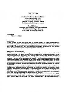
transform using technical unit repository
refine
transform using deployment unit repository
Coarse-grained Architecture Architecture decomposed into Architectural Units
Technical Unit Repository
Architectural Units decomposed into Technical Units
Deployment Unit Repository
Technical Units decomposed into Deployment Units
Fig. 1: Overview of the MADCAT Approach
III.
T HE MADCAT M ETHODOLOGY
In this section, we introduce MADCAT— a Methodology for Architecture and Deployment of Cloud Application Topologies based on iterative refinement. Our methodology is designed to tackle practical challenges encountered in realizing large software projects, such as the multitude of involved stakeholders with different levels of business and technical expertise, and the arising requirement for communication and reporting on different levels of abstraction. Moreover, complete information about business and technical requirements is usually not readily available in early stages of a project but emerge and evolve over time as the project progresses. We furthermore posit that decisions within a project should be made as late as possible and as early as necessary to minimize risks such as over-engineering, requirements creep [11], feature creep [12], premature optimization [13], and vendor lock-in. We tackle these problems by introducing a methodology to iteratively refine an application architecture based on stakeholders’ requirements, from a coarse-grained abstract representation of the target application capturing general business requirements to a concrete model of application components to be deployed on cloud infrastructure, as shown in Figure 1. To achieve this transition, we introduce the concepts of architectural units, technical units, and deployment units. Architectural units represent functional concerns in an application structure, such as storage or computation. These functional concerns are mapped to technical units according to functional requirements using a decision tree structure allowing proper assessment of possible technology decisions based on their merits for the application under development. The modeled technical units are subsequently refined to deployment units guided by customer requirements, using a repository of available deployment units that are suitable to realize modeled technical units. The resulting application’s deployment topology is provisioned and deployed on cloud infrastructure with the help of our deployment infrastructure repository that orchestrates deployment of concrete artifacts on cloud infrastructure using offerings most suitable to fulfilling customer requirements. In the following, we discuss the introduced concepts of architectural, technical, and deployment units in greater detail. A. Architectural Units One of the guiding principles of the proposed approach is to take decisions as late as possible and as early as necessary.
Because, when starting to design an application with the customer little is known about it, and only a general idea of the desired outcome exists. Application architects create an initial, abstract view of the application in cooperation with the customer’s executive stakeholders. This abstract view is subsequently refined into a coarse-grained application architecture, as more information is gathered through requirements elicitation and requirements engineering processes. Several state of the art approaches are suitable for this task, such as goal-based approaches like KAOS [32], and priority analysis methods [33]. Iteratively, functional specifications are created that represent the stakeholders’ requirements and expectations towards the application to be. Our method is designed to support this incremental process by iteratively refining the abstract view of the application, annotated with business requirements, into more detailed representations of the application architecture. Application architects closely work with customer stakeholders formulating their requirements to refine the application architecture until it is composed solely of architectural units. Architectural units (AU) represent technology-independent functional concerns, such as storage or computation, and serve as reusable fragments, or building blocks, for application composition. To aid software architects in their task, our methodology incorporates a repository of AUs, allowing for reuse of gathered knowledge across teams, departments, and even companies. The AU repository furthermore simplifies and encourages the adoption and maintenance of architectural best practices by documenting and capturing stakeholder expertise. If necessary, application architects will create additional AUs to realize customer requirements and add them to the AU repository. An application architecture composed of AUs still provides an abstract view on the application to be and is suitable for further collaboration on application’s design with customer’s executive stakeholders. B. Technical Units After decomposing the application architecture into AUs, application architects, engineers, and customer’s technical staff transform AUs into technical units (TUs), using TU decision trees and questionnaires. A TU represents a technique or pattern that can be used to realize an AU. TUs serve as mediation layer between abstract architectural concerns
and concrete deployment artifacts, capturing implementationindependent technology decisions. Usually, multiple possible TUs are available for realizing an AU, calling for a structured way of mapping AUs to TUs and documenting the decision process. To facilitate this structured approach, MADCAT employs decision trees to support stakeholders in realizing the mapping between high-level architectural concerns and TUs. Decision trees provide detailed guidelines on how to translate an AU to a set of TUs that represent possible technical realizations of the AU. A decision tree contains three types of nodes: 1) a root node that represents an AU, 2) a set of leaf nodes that represent the TUs, and 3) decision nodes used to connect the root node with leaf nodes. Decision nodes represent evaluation criteria and are used to navigate from the AU (the root node) to a particular TU (a leaf node), depending on the application requirements and other design decisions or constraints. Evaluation criteria represent a set of conditions, which a stakeholder, e.g, a solution architect, might require from an application, executed on a cloud platform, to be fulfilled. Further, it can be used to describe some of the features of an application. For example, if it needs to store non-relational real-time or more traditional relational data. Therefore, evaluation criteria provide information used to reduce the technical units search space, thus, supporting the stakeholder to design cloud-based applications and provision the required resources. However, applicability of the criteria depends on a concrete problem and type of the AU, but also different stakeholders will have different understanding and requirements regarding it. The resulting application architecture composed of TUs serves as documentation of design decisions taken and can be used to communicate and coordinate these decisions with customer’s technical staff. C. Deployment Units Following the decomposition of the application architecture into TUs, application architects work with engineers and operations experts to identify concrete components – or deployment units (DU) – to be used in the implemented application. A DU is a part of the application’s deployment topology for realizing a specific TU. For each TU we create one or more DUs that describe how the TU can be deployed in a cloud environment. DUs metadata consists of a utility function to allow stakeholders to properly assess elasticity dimensions and other non-functional properties affected by the DU. This process is aided by the use of the DU repository, providing management and query facilities to efficiently perform the mapping between a TU and DUs. As with earlier phases, DUs are created and added to the repository as necessary to capture gathered knowledge for later reuse. The resulting architecture composed of DUs is suitable for communication and coordination with the customer’s system operators to align the application structure with possible infrastructure requirements and constraints. The application architecture composed solely of DUs is used to identify a) business logic components that need to be implemented specifically for the application to be, along with
b) reusable stock components that only need to be configured for integration with the application, (e.g., a database server). In MADCAT, custom business logic components and stock component are treated largely in the same way. While the implementation of business logic components will certainly call for larger efforts, the resulting artifacts are packaged and deployed with configuration directives, just as any other component. Configuration directives are contained in the deployment infrastructure repository (DIR). The DIR provides a catalog of concrete deployment artifacts to provision DUs on cloud instances, and serves as an abstraction layer between DUs and different provisioning technologies. The DIR contains multiple infrastructure mappings for specific DUs, allowing flexible provisioning using different configuration management solutions, such as Chef recipes for use with OpsCode Chef5 or Amazon OpsWorks6 , or Puppet manifests for use with Puppet7 . Additionally, the DIR manages application deployment orchestration using provider-independent communication facilities, such as [34], [35], Apache jClouds8 , or fog9 to minimize the risks of vendor lock-in. By treating business logic artifacts similar to component configuration artifacts, we allow for the generalization of created business logic components into DUs, making them proper first-class citizens in our methodology. The resulting application’s deployment topology along with according configuration directives can be directly applied on cloud infrastructure to provision necessary resources on demand, install relevant software packages, perform necessary configuration to establish connections between application components, and execute the application. IV.
C ASE S TUDY
In this section, we demonstrate the feasibility of the methodology using a fleet management (FM) scenario application for small-wheel, zero-emissions electric vehicles deployed on golf courses10 . MADCAT
Electric vehicle information systems consist of onboard hardware and software platforms that are tightly coupled with the vehicles and their usage scenario – mainly as golf cars. The main features provided by the onboard system include 1) vehicle maintenance (odometer monitoring, maintenance schedule, fault history, battery health, crash history, and engine diagnostics), 2) vehicle tracking (position, driving history, find car, pace of play, and geo-fencing), 3) vehicle info (charging status, odometer, serial number, and service notification), 4) set-up (club-specific information, maps, and fleet information), as well as additional market apps for golfers, such as food & beverages apps, etc. Additionally, the FM solution needs to accommodate for various business requirements. New cars are leased to golf courses for a certain period of time. At the end of each 5 http://opscode.com/chef 6 http://aws.amazon.com/opsworks/ 7 http://puppetlabs.org 8 http://jclouds.org 9 http://fog.io 10 The use case is extracted from our ongoing collaboration with industrial partners but the company name is omitted to protect business information.
lease, the cars are reclaimed, refurbished, and resold to second markets such as supermarkets and recreational parks. The cars in lease are geographically distributed in many golf courses, and the number of cars is expected to have exponential growth in the next years. Due to the fact that a considerable number of cars can be lost or damaged during the initial leasing period, the FM platform is aimed at collecting and managing relevant information about the status of all deployed cars to a cloud application to improve the company’s operational efficiency and relationship with the customers. Vehicles communicate with the platform via 3G or GPRS to exchange telematic and diagnostic data. The application manages this data and provides a set of core services: 1) Realtime vehicle status: location, driving direction, speed, driver operations, vehicle faults; 2) Remote diagnostics: diagnostics of equipment status, battery health, etc. and sending timely maintenance reminders and instructions; 3) Remote control: overriding onboard vehicle control system in case of emergency, e.g. to restrict the motion of vehicle when it’s driving out of course; 4) Batch configuration and software updates: remotely configure course maps, course information and software feature set for a fleet, applying software updates, and installing new value-added services to a large number of cars; 5) Fleet management: managing customers’ fleets, service history, fleet usage patterns. Obviously, these core services need to be provided by a reliable and responsive platform so that they can improve user experiences on top of the existing onboard system. Therefore, the service platform needs to accommodate the scale of the current FM offering as well as support projected growth in the future. In the following, we demonstrate how the MADCAT methodology is applied in the design of the FM application. A. From Requirements to Architectural Units In this section, we elaborate how to use MADCAT to iteratively design, provision, and deploy the aforementioned FM application. As mentioned in Section III, MADCAT allows stakeholders to take decisions as late as possible and as early as necessary. As illustrated in Figure 2, our approach embraces this notion of uncertainty and allows stakeholders to represent the application as an abstract artifact, annotated with the business requirements gathered so far. Fleet Management
Availability ≧ .9995 ISO 9001 compliance ...
In the FM scenario, we start the refinement process by first analyzing how the external clients, namely customers and vehicles, that interact with the application. With respect to the customers, the responsibility of the application is to provide Web UI that can be used by customers directly and an external API (e.g. REST) that can be used third-party applications (e.g., food & beverages app). On the other hand, the responsibility of the application towards vehicles is to provide an IoT interface to receive information about their current state. Due to the fundamentally different ways these two external clients communicate with the application, we can immediately distinguish that the application will require two frontend AUs: Web interface and IoT connector (see Figure 3). The next step in the refinement process is to introduce an AU that will be responsible for persisting the application’s data, such as sensory information received from vehicles. Hence, as shown in Figure 3, we introduce the Storage AU that will fulfill this requirement. Further refinement steps introduce the Monitoring AU to deal with the online monitoring of information received from vehicles and reacting/processing this information based on some business rules, the Authorization AU to deal with the single sign-on requirement that was requested by the customers, and App Server to deal with execution and coordination of long running business processes. Figure 3 shows the finalized architecture diagram for the vehicle fleet management scenario application, refined to contain only AUs, their communication partners (signified by connections between units), as well as requirements applicable to them. elastic Location = Dubai elastic
elastic
«Computation»
Storage
App Server data-intensive
Authorization elastic
elastic «Computation»
Monitoring
elastic
«Frontend»
«Frontend»
Web Interface
IoT Connector Fleet Management
Gateway
Car/Sensors
Customer Car/Sensors
Fig. 3: Application Architecture using Architectural Units
At this stage, the requirements call for these functional concerns to be met in the resulting application, but no decision on technical realization needs to be taken yet, deferring the technical decisions as much as possible, so they can be taken with the sufficient knowledge about the application. B. From Architectural Units to Technical Units
Gateway
Car/Sensors
Customer Car/Sensors
Fig. 2: Abstract View of Application with Business Requirements
In this section we describe the second step of the iterative architectural refinement process. The input to this step is the end-result of the previous phase (see Section IV-A). Therefore, in this phase a stakeholder, e.g., a solution architect takes the proposed FM application template, containing the necessary
Storage
Real-Time Data
Small Data
Immediate Consistency
Write Intensive
Monolithic RDBMS
Read Intensive
Eventual Consistency
Fault Tolerant
Master/Slave RDBMS
Big Data
Current State
Complex
Simple
Relational
Document Based
Key/Value
Graph Based
History
Complex
Simple
Column Family
Key/Value
Non Persistent
Persistent
Memory Image
Fig. 4: Example of a Decision Tree for the Architectural Unit storage.
We notice that this process offers different advantages to the stakeholders involved into designing, developing and provisioning of applications executing in cloud platforms. For example, separation of concerns and different logical views on the design and development process, which enable different stakeholders to articulate their goals and constraints on cloud applications. Additionally, by carefully choosing the granularity of the resources and TUs and providing suitable evaluation criteria we can (at-least partially) automate the decision process and in some cases even defer decisions to the runtime.
Governance
Location = Dubai elastic
elastic
Business Activity Monitor
Identity
elastic
NoSQL Key/Value
elastic
RDBMS Master/Slave
elastic
elastic data-intensive
App Server
Data Server data-intensive
Enterprise Service Bus
Web Interface
elastic
elastic
elastic
IoT Connector Fleet Management
Gateway
Car/Sensors
Customer Car/Sensors
Fig. 5: Application Architecture refined with Technical Units
TUs and decide on how they are concretely realized using specific technologies and will be deployed in a cloud environment. The output of this step is the deployment topology of the FM cloud application. «cluster» «instance»
«instance»
Cassandra
... ...
...
Figure 4 illustrates a decision tree (as described in Section III-B), which maps the AU storage to a set of TUs, which represent possible technical realization of storage for the FM application. As we have seen in Section IV-A, storage is one of the crucial AUs utilized by the FM application. Therefore, a solution architect will need to choose among the multiple possibilities to store data in the data center. The first criteria in the decision tree is the type of data, which will be stored. In this case we know there will be a high volume of real-time sensory data generated by the vehicles. Further, due to stakeholder’s business requirements, the history of the vehicle performance, is very important. Therefore, we need to support different (possibly off-line) analytics about vehicle’s status like maintenance history, battery condition and warranty, motor status, location, tire pressure and so forth. Based on the decision tree (see Figure 4), we notice that these requirements match the big data decision node. In our case, we have two options how to store big data, depending on its complexity. Finally, a solution architect can choose the key-value TU, because the data model will be naturally centered on a vehicle entity. The resulting, complete technical architecture for the FM application is shown in Figure 5.
Location = Dubai elastic
...
AUs and further refines it into the technical architecture of the FM cloud application.
...
Cassandra
«instance»
Cassandra
Cassandra
«instance»
costDU(n, t) = n × costI(t) n – number of instances t – type of virtual machine + Masterless clustering + Linear scalability + No single point of failure + Suitable for BigData + MapReduce with Hadoop - Slow scaling down
Fig. 6: Apache Cassandra Deployment Unit
C. From Technical Units to Deployment Units In this section, we present the third step of the iterative architectural refinement process. The input of this step is the end result of the previous section (see Section IV-B). In this phase, stakeholders, e.g., system operators take the proposed
In the previous section, we concluded that FM application requires the key-value TU for storage of the sensory data generated by deployed vehicles. Taking this as input, we can generate DUs for multiple key-value databases like Apache
Cassandra11 , Riak12 , Voldemort13 and so forth. As an example, Figure 6 shows the DU for the Apache Cassandra key-value database. Each Apache Cassandra instance is represented as a concrete node and tagged with the «instance» class. Furthermore, all Apache Cassandra instances are composed in a cluster and hence represented as a logical node that is tagged with the «cluster» class. Because a cluster can consist of any number of Apache Cassandra instances, we represent this with the ellipsis sign between them. To calculate the utility of this DU (see Section III-C), we provide a cost function and a table of benefits. The cost function for an Apache Cassandra DU, costDU (n, t) = n × costI (t), depends on the number of instances n and costI , the cost of deploying it on the underlying infrastructure, e.g., virtual machine type t. Finally, Figure 6 shows the table of benefits and drawbacks for using Cassandra DU.
Location = Dubai
Service Registry Service Repository Governance Load Balancer
Location = Dubai Monitoring Reporting Billing
User Mgmt Single Sign On Identity
NoSQL Data Facade Relational Data Facade Data Server
Bus. Act. Mon.
Load Balancer
Load Balancer
Load Balancer
Load Balancer
read/ write
read Vehicle Tracking Live Tracking Service Registry Vehicle Monitoring Service Repository Vehicle Management Application Server
Message Mediation Proxy Services Service Registry APIs Service Repository Ent. Service Bus Load Balancer
PostgreSQL Master
Load Balancer
PostgreSQL Hot Standby Slave
Cassandra Node NoSQL Key/Value
RDBMS Master/Slave Fleet Management
Gateway
Car/Sensors
Customer Car/Sensors «write»
«read» «cluster» «slave»
Slony
«master»
Postgres
Postgres
Slony
...
Slony
«slave»
Postgres
costDU(n, t) = cost(master) + n × costI(slave) n – number of slave instances master – type of the master virtual machine slave – type of the slave virtual machines + (Partial) replication of data + Good for read intensive data + Fault tolerant w.r.t. read - Single point of failure with master - Slow scaling
Fig. 7: Postgres Deployment Unit
In this example we only used two types of classes, namely instance and cluster, but other DUs can use other classes like web server, load-balancer, storage, master, slave, application server, and so forth. An additional example for a Master-Slave Postgres14 with Slony15 DU is presented in Figure 7. This DU can be used for the Master/Slave Storage TU in the decision tree from Figure 4. A complete deployment topology of the FM application is shown in Figure 8. We can notice that the decisions that lead from requirements to AUs, then from AUs to TUs, and finally from TUs to DUs will be preserved and can easily be conveyed to different stakeholders. The final step in the scenario is to use the derived DUs, i.e., FM deployment topology and select appropriate configuration directives that are suitable for automatically deploying the application on cloud infrastructure. For example, the following Chef recipe is queried from the DIR and used to instantiate the Cassandra DU in the cloud environment: template "#{node[:cassandra][:conf_dir]}/cassandra.yaml" do source "cassandra.yaml.erb" owner "root" group "root" mode "0644" variables({ :cassandra => node[:cassandra], :seeds => seed_ips }) notifies :restart, "service[cassandra]", :delayed if startable?(node[:cassandra]) end 11 http://cassandra.apache.org 12 http://basho.com/riak/ 13 http://www.project-voldemort.com/voldemort/ 14 http://www.postgresql.org 15 http://www.slony.info
Fig. 8: Fleet Management Application Deployment Topology
This recipe together with other configuration directives for the rest of the DUs, allows provisioning of necessary resources in the cloud environment and hence ensures correct execution of our FM application. V.
C ONCLUSION
The cloud computing paradigm introduces new possibilities and challenges to be considered in application design and deployment. On-demand resource provisioning, as well as resource and cost elasticity, need to be considered when realizing large-scale distributed cloud applications. In this paper we presented MADCAT, a methodology tackling the practical problems faced when designing and deploying cloud applications. Current approaches do not sufficiently address the specific challenges encountered when architecting and deploying applications on cloud infrastructure in a holistic manner. MADCAT enables the structured creation of cloudnative applications, covering the complete application development lifecycle, from architectural design to concrete deployment topologies provisioned and executed on cloud infrastructure. We introduced the concepts of architectural units to encapsulate functional concerns, technical units to encapsulate technical design decisions, as well as deployment units to map from technical concerns to deployable artifacts on cloud infrastructure. By using iterative refinement and seamless provenance documentation of decisions made in the process, MADCAT simplifies communication with relevant stakeholders and enables efficient design and deployment of distributed cloud applications. We discussed the feasibility of the introduced method using a case study from the vehicle fleet management domain and illustrated the practical advantages of the introduced concepts and documentation artifacts. As part of our future work, we will implement comprehensive tool support to assist and simplify the adoption of the MADCAT methodology for creating cloud-native applications, and will integrate our work on creating cloud-based IoT applications [36]. We further plan to extend the presented notion of technical unit to incorporate social compute units [37] to allow for effective modeling of mixed systems.
ACKNOWLEDGMENT The research leading to these results was supported by the Pacific Controls Cloud Computing Lab16 (PC3L), as well as the Austrian Science Fund (FWF) under grant P23313-N23 (Audit 4 SOAs).
[19]
[20]
R EFERENCES [1]
[2] [3]
[4]
[5] [6]
[7]
[8] [9] [10]
[11] [12]
[13] [14]
[15]
[16]
[17]
[18]
M. Armbrust, I. Stoica, M. Zaharia, A. Fox, R. Griffith, A. D. Joseph, R. Katz, A. Konwinski, G. Lee, D. Patterson, and A. Rabkin, “A view of cloud computing,” Communications of the ACM, vol. 53, no. 4, pp. 50–58, Apr. 2010. S. Dustdar, Y. Guo, B. Satzger, and H.-L. Truong, “Principles of elastic processes,” Internet Computing, IEEE, vol. 15, no. 5, pp. 66–71, 2011. G. Copil, D. Moldovan, H.-L. truong, and S. Dustdar, “SYBL: An extensible language for controlling elasticity in cloud applications,” International Symposium on Cluster, Cloud and Grid Computing, pp. 112–119, 2013. D. Moldovan, G. Copil, H.-L. truong, and S. Dustdar, “MELA: Monitoring and analyzing elasticity of cloud services,” in International Conference on Cloud Computing Technology and Services. IEEE, 2013, pp. 80–87. T. Erl, R. Puttini, and Z. Mahmood, Cloud Computing: Concepts, Technology & Architecture. Prentice Hall, 2013. P. Kruchten, R. Capilla, and J. C. Dueas, “The decision view’s role in software architecture practice,” Software, IEEE, vol. 26, no. 2, pp. 36–42, 2009. C. Inzinger, W. Hummer, I. Lytra, P. Leitner, H. Tran, U. Zdun, and S. Dustdar, “Decisions, models, and monitoring – A lifecycle model for the evolution of service-based systems,” in Proceedings of the International Enterprise Distributed Object Computing Conference. IEEE, 2013, pp. 185–194. P. Kruchten, The Rational Unified Process: An Introduction, 3rd ed. Addison-Wesley Professional, 2004. H. Takeuchi and I. Nonaka, “The new new product development game,” Harvard Business Review, vol. 64, no. 1, pp. 137–146, 1986. M. Poppendieck and T. Poppendieck, Lean Software Development: An Agile Toolkit, ser. The Agile software development series. AddisonWesley Professional, 2003. C. Jones, “Strategies for managing requirements creep,” Computer, vol. 29, no. 6, pp. 92–94, 1996. B. Elliott, “Anything is possible: Managing feature creep in an innovation rich environment,” in Proceedings of the International Engineering Management Conference. IEEE, 2007, pp. 304–307. D. E. Knuth, “Structured Programming with go to Statements,” ACM Computing Surveys, vol. 6, no. 4, Dec. 1974. F. Liu, J. Tong, J. Mao, R. Bohn, J. Messina, L. Badger, and D. Leaf, “NIST cloud computing reference architecture,” NIST Special Publication – 500-292, Sep. 2011. [Online]. Available: http: //www.nist.gov/manuscript-publication-search.cfm?pub_id=909505 L.-J. Zhang and Q. Zhou, “CCOA: Cloud computing open architecture,” in Proceedings of the International Conference on Web Services. IEEE, 2009, pp. 607–616. Y.-W. Kwon and E. Tilevich, “Cloud refactoring: automated transitioning to cloud-based services,” Automated Software Engineering, Oct. 2013. [Online]. Available: http://dx.doi.org/10. 1007/s10515-013-0136-9 D. Ardagna, E. di Nitto, P. Mohagheghi, S. Mosser, C. Ballagny, F. D’Andria, G. Casale, P. Matthews, C. S. Nechifor, D. Petcu, A. Gericke, and C. Sheridan, “MODAClouds: A model-driven approach for the design and execution of applications on multiple clouds,” in Proceedings of the Workshop on Modeling in Software Engineering. IEEE, 2012, pp. 50–56. T. Binz, G. Breiter, F. Leyman, and T. Spatzier, “Portable cloud services using TOSCA,” Internet Computing, IEEE, vol. 16, no. 3, pp. 80–85, Mar. 2012.
16 http://pc3l.infosys.tuwien.ac.at/
[21]
[22]
[23]
[24]
[25]
[26]
[27]
[28]
[29]
[30]
[31]
[32]
[33] [34]
[35]
[36]
[37]
M. Lucena, J. Castro, C. Silva, F. Alencar, and E. Santos, “Stream: a strategy for transition between requirements models and architectural models,” in Proceedings of the Symposium on Applied Computing. ACM, 2011, pp. 699–704. J. Castro, J. Pimentel, M. Lucena, E. Santos, and D. Dermeval, “FSTREAM: A flexible process for deriving architectures from requirements models,” in Advanced Information Systems Engineering Workshops, ser. LNBIP. Springer Berlin Heidelberg, 2011, vol. 83, pp. 342–353. D. Dermeval, J. Pimentel, C. Silva, J. Castro, E. Santos, G. Guedes, M. Lucena, and A. Finkelstein, “STREAM-ADD - Supporting the documentation of architectural design decisions in an architecture derivation process,” in Proceedings of the Computer Software and Applications Conference. IEEE, 2012, pp. 602–611. M. Svahnberg, C. Wohlin, L. Lundberg, and M. Mattsson, “A qualitydriven decision-support method for identifying software architecture candidates,” International Journal of Software Engineering and Knowledge Engineering, vol. 13, no. 05, pp. 547–573, 2003. I. Krka, G. Edwards, Y. Brun, and N. Medvidovic, “From system specifications to component behavioral models,” in Proceedings of the International Conference on Software Engineering. IEEE, 2009, pp. 315–318. R. J. Machado, J. M. Fernandes, P. Monteiro, and H. Rodrigues, “Refinement of software architectures by recursive model transformations,” in Product-Focused Software Process Improvement, ser. LNCS. Springer Berlin Heidelberg, 2006, vol. 4034, pp. 422–428. U. Zdun, C. Hentrich, and S. Dustdar, “Modeling process-driven and service-oriented architectures using patterns and pattern primitives,” ACM Transactions on the Web, vol. 1, no. 3, pp. 14:1–14:44, Sep. 2007. U. Zdun and P. Avgeriou, “Modeling architectural patterns using architectural primitives,” in Proceedings of the Conference on Objectoriented Programming, Systems, Languages, and Applications. ACM, 2005, pp. 133–146. I. Lytra, H. Tran, and U. Zdun, “Supporting consistency between architectural design decisions and component models through reusable architectural knowledge transformations,” in Software Architecture, ser. LNCS. Springer Berlin Heidelberg, 2013, vol. 7957, pp. 224–239. F. Loiret, A. Plsek, P. Merle, L. Seinturier, and M. Malohlava, “Constructing domain-specific component frameworks through architecture refinement,” in Proceedings of the Euromicro Conference on Software Engineering and Advanced Applications. IEEE, 2009, pp. 375–382. M. Moriconi, X. Qian, and R. A. Riemenschneider, “Correct architecture refinement,” Transactions on Software Engineering, IEEE, vol. 21, no. 4, pp. 356–372, Apr. 1995. D. Batory, J. N. Sarvela, and A. Rauschmayer, “Scaling step-wise refinement,” in Proceedings of the International Conference on Software Engineering. IEEE, May 2003. T. Haase, O. Meyer, B. Böhlen, and F. Gatzemeier, “Fire3: Architecture refinement for a-posteriori integration,” in Applications of Graph Transformations with Industrial Relevance, ser. LNCS. Springer Berlin Heidelberg, 2004, vol. 3062, pp. 461–467. A. Dardenne, A. van Lamsweerde, and S. Fickas, “Goal-directed requirements acquisition,” Science of Computer Programming, vol. 20, no. 1, pp. 3–50, 1993. K. E. Wiegers, Software Requirements, 2nd ed. Microsoft Press, 2009. B. Martino, D. Petcu, R. Cossu, P. Goncalves, T. Máhr, and M. Loichate, “Building a mosaic of clouds,” in Euro-Par 2010 Parallel Processing Workshops, ser. LNCS. Springer Berlin Heidelberg, 2011, vol. 6586, pp. 571–578. B. Satzger, W. Hummer, C. Inzinger, P. Leitner, and S. Dustdar, “Winds of change: From vendor lock-in to the meta cloud,” Internet Computing, IEEE, vol. 17, no. 1, pp. 69–73, 2013. S. Nastic, S. Sehic, M. Vögler, H.-L. Truong, and S. Dustdar, “PatRICIA – a novel programming model for iot applications on cloud platforms,” in International Conference on Service Oriented Computing and Applications. IEEE, 2013, pp. 53–60. S. Dustdar and K. Bhattacharya, “The social compute unit,” Internet Computing, IEEE, vol. 15, no. 3, pp. 64–69, 2011.