Magnetic Optimization of a Fault-Tolerant Linear Permanent Magnet Modular Actuator for Shipboard Applications M. Bortolozzi(+), C. Bruzzese(*), F. Ferro(*), T. Mazzuca(x), M. Mezzarobba(+), G. Scala(o), A. Tessarolo(+), and D. Zito(*) (+) Dept. of Engineering and Architecture (DIA) University of Trieste - Italy (*) Dept. of Astronautical, Electrical, and Energy Engineering (DIAEE) University of Rome Sapienza - Italy
[email protected] (x) Electrical Plants Office Italian Navy's General Staff (MARISTAT) – Italy (o) General Directorate of Naval Armaments Italian Ministry of Defense (NAVARM) - Italy
1
Outline of the presentation ● Research about “all electric” ships ● Description of classical oil-powered steering gears ● Mechanical structure of the proposed direct-drive concept ● Magnetic optimization by FEM for force density maximization ● Inverter feeding scheme and winding sizing ● Torque-speed operating area and efficiency ● Laboratory prototype ● Applications: rudders and stabilizing fin drives ● Conclusions
2
●“All-electric“ ships are object of growing interest and research ● Electric propulsion (synchronous PM motors, multi-phase or multi-star windings, VSI/CSI converters, azimuth thruster pod drives, etc.) ● Ship electric system (DC transmission, stability, reliability, grid segmentation, harmonic pollution due to converters, coordination of load and generators, high speed turbogenerators, etc.) ● Reasons: more power is needed on modern ships (both commercial and military ships), so propulsion is no more the only relevant load, and a centralized electric power generation becomes convenient (more electrical loads are allowed!) ● A challenging sub-topic concerns the innovation of traditional oil-powered onboard actuators, for steering gears, stabilizing fins, pods, bow-thrusters, launch and lift systems, etc. ● New solutions based on inverter-fed drives are emerging, and also direct-drives (with no reduction gears). 3
Hydraulic steering gear on board ship “Etna“
MANY REDUNDANT OIL SUPPLIES BUT...ONLY ONE MOTOR!
4
induction motor
218 l/min 59bar
i.m.
p.
pilotoperated check valve
two-way electrovalve
75 bar
B
T 26kW
ηim=90%
B1
ηp=81%
75 bar
r.
ηvp=75%
Hydraulic circuit, singlepump rated operation
0.387rpm
Powers and efficiencies are shown
13kW
Overall plant efficiency = 44%
16kW
ηvm=80%
46.2%
44.3%
maximum power operating point rated power operating point
604 STALL
462
v.m.
B2
21kW
Tm(kNm) η(%)
vane motor pressure-relief valve opening
rudder 322kNm
44bar
1750rpm
29kW
pressure-relief valve
vane-motor valve pipes A1 A2 A
P
145Nm
ship grid
pump valve
MAXIMUM TORQUE
Torque-speed curves, with one and two pumps
34Kw
322
RATED TORQUE
26Kw pump pressurerelief valve opening
17Kw
Output powers and efficiencies are shown
13Kw VUOTO
0
0.35 0.39 0.47 SINGLE-PUMP OPERATION
0.7
0.77
TWO-PUMPS OPERATION
0.94
ωm (rpm)
5
Drawbacks of hydrostatic transmissions: - Maintenance is heavy and troublesome. Seals and filters must be routinely checked and replaced (require pump dismounting). Oil refill/replacement is time-consuming and costly. Oil leaks are frequent. - Plant efficiency is low. - Plant weight and size are very large; plant encumbrance is heavily increased by pipes, valves, bulky oil tanks, etc. - Plant complexity and cost is high. - Plant control is slow and sluggish. A continuously running pump is required with relevant no-load losses. - No redundancy for the vane motor. Only the pumps are redundant.
Good features of hydrostatic transmissions: - Very high torques/forces. - Mechanically robust and affordable (with continuous maintenance!) - Simple operating principle 6
PROTECTIVE COVER
PMLSM CONCEPT
ARM
RUDDER STOCK
MOVER HEAD ROTARYPRISMATIC JOINT
BRAKE
STATOR WINDINGS
SLIDER
MOVER WITH MAGNETS
7
8
80
300
310
80
104
9
10
redundant power sources
11
INTEGER-SLOT DESIGN
REMOVABLE THREE-PHASE MODULE
the winding end-connections of neighboring modules cannot overlap, so the end connections must be put at least on three orders and they require more space and copper, with higher joule losses.
12
FRACTIONAL-SLOT DESIGN
THREE-PHASE MODULE
REMOVABLE SUB-MODULE (TOOTH+COIL)
-Shorter end connections (saving of copper, space, losses) -Smaller air gap force density -The space saved can be used to design a larger module. -Finally, the higher simplicity, modularity and the easier module dismounting, substitution and reparation are the decisive features.
13
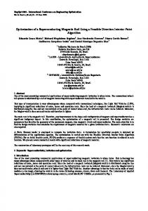
FEM analysis: Parametric model (integer slot)
+A
-C
+B
-A
+C
-B
F '=
F =B J ' Lx p
14
2.05T 1.96T 1.80T 1.47T
2.02T 2.02T 1.93T 1.84T
143kN/m2
150kN/m2
636kN/m3
667kN/m3 +5%
flux density, 5A/mm2(rms) – maximum thrust condition magnet flux and current in quadrature 15
F'(kN/m2)
Force per unit of airgap area vs. parameter 'a'
a(mm) 16
FEM analysis: Parametric model (fractional slot)
F '=
F BJ' = Lx p H H
17
QUASI-NEWTON ALGORITHM
SEQUENTIAL NON-LINEAR PROGRAMMING ALGORITHM
18
Gradient-based methods may remain trapped in local minima due to FEM numerical noise
19
“GEOMETRY STRETCHING” METHOD (GSM)
h
l
20
MAX FORCE DENSITY
Force per unit of machine volume (Fv) on the length-height plane (GSM applied to the starting geometry).
Contours of the surface Fv on the length-height plane (values in kN/m 3) (GSM applied to the starting geometry)
(FINAL)
(START)
(FINAL)
(START)
26
Force vs Slot current density (integer slots)
157kN/m2
ABOUT +50% MORE THRUST DENSITY THEN IN USUAL COMMERCIAL MOTORS PEAK SHORT-TERM THRUST IN COMMERCIAL MOTORS: 104kN/m2 (TYPE: BALDOR® IRON CORE BRUSHLESS LMIC-71-S-HCO-X) 27
Final drive sizing for rudder application (integer slot) 3 SEPARATE INVERTER
GRID INVERTER1
INVERTER2
INVERTER3
PHASE-COIL
STAR-CENTERS
+ A
C
+ B
A
+ C
B
28
Equations for winding sizing ● Nc : Number of turns per coil ● ns, np: Series and parallel coils in a phase current vector
V≈RsI+ωΨm
n p ρ lm N c R s = s R coil = np A np m= n s N c φ m
magnet
V
r Rs m V= F v 3 m r
2
E
I
motor torque
sud I
jXsI RsI
o
S
N
o
90 ψm
electronically-controlled in-quadrature lag VECTOR DIAGRAM
stator current
nord ANALOGOUS ROTARY MACHINE
φm=Fr/3pJA
V max r ρl m φ p = F mp m vmp =3.32V N c / n p 3φ m A r
29
ψm
x
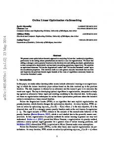
V max r ρl m φ p = F mp m vmp =3.32V N c / n p 3φ m A r
F(kN)
v = ω*a
3ΨmV/Rsr
inverter power limit
inverter current limit maximum power operating point (82kW)
inverter voltage limit
137 STALL
160
162
167
182
186
196
MAX FORCE 343 47
65
66
70
82
85
93
27
28
31
39
41
47
16
17
20
449
239
120
0
F=T/ a
15 RATED FORCE
4
HALF RATED FORCE10
10
rated operating point (41kW) 12
0
NO-LOAD
0
0
0
0
0
5 5.5
6.6
9.9
11
13
0
curves of the hydraulic drive
v(cm/s) rV/Ψm
PMLSA working area on the v-F plane. The working area is bounded by the inverter's current and voltage limiting curves (bold lines). The PMLSA input electric power Pe=3VIcosφ is also plotted on the plane.
30
F (kN)
F' (kN/m2)
J' = F'/B LINEAR
J' = F'/B+f(B)F'2 343
157 MAX FORCE SATURATED
239
109
0
RATED FORCE
112
200
J'(A/mm)
2.8
5
J(A/mm2)
Resistive power losses P ρ=3 R s I 2=∫ ρ J 2 d = ρ J 2 cu P ρ v , F ≃
2
ρ cu s 2
2
2
2
2
A B bs hs
F
2
2 ρ cu s f B 3
2
2
A B bs hs
Mech. output power
P m v , F =F⋅v
Electr. input power
P e v , F = P m P ρ= Fvk 1 F k 2 F
Motor efficiency
Pm Pm Fv PMLSA= ≃ = P e P m P ρ F v ρ J 2 cu
2
3
2
F = k1 F k2 F
3
31
3
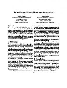
CONSTANT EFFICIENCY CURVES
Pm(kW) F (kN)
13
17
26
η(%)
34
0 STALL
14
15
18
25
26
30
343 0 MAX FORCE
26
28
32
42
44
49
44
46
51
61
63
67
449
239
120
0 RATED FORCE
67
76
77
90*
90*
90*
90*
90*
90*
50**
50**
50**
50** 50**
0 HALF RATED FORCE 61
0 NO-LOAD
0
63
rated operating point 81
5 5.5
6.6
9.9
11
50**
v 13 (cm/s)
PMLSA efficiency (4) on the speed-force plane. Dash-dot lines are constant-efficiency loci. Maximum (*) and noload (**) values depend on mechanical friction losses, on stray losses and on additional losses due to inverter feeding, so they have been only approximately evaluated.
32
33
DESIGN AND REALIZATION OF THE PMLSA CONCENTRATED COIL MAGNETS
MODULAR STATOR
MOVER FRAME BEARINGS 34
PROTOTYPED MACHINE
MODULAR STATOR
MAGNETS MOVER
BEARINGS
35
PROTOTYPED MACHINE
MAGNETS LATERAL AXES (FRAME)
MOVER
FOOT
36
PROTOTYPED MACHINE
TOOTH COILS
BACK-IRON
BACK-IRON AND TOOTH ARE INTEGRATED IN A SINGLE PIECE WITH STRUCTURAL FUNCTION
37
MEASURED VS PREDICTED FORCE CURRENT AND MAGNET FLUX ARE IN QUADRATURE
38
DOUBLE RUDDER (MMI's Ship “Durand de la Penne”) -project under examination by the Italian NavyHYDRAULIC MOTOR TILLER#2
TILLER#1 TRANSMISSION ROD
RUDDER STOCK
39
PMLSA
TILLER#2
TILLER#1
THE MOTOR REPLACES THE TRANSMISSION ROD
RUDDER STOCK
Double rudder drive concept
40
Stabilizing fin drive concept
41
42
43
Conclusions: ●
Oil is really a problem on board ships
●
Inverter-fed drives are demanded for ships
●
Direct-drives are preferred for affordability
●
A PMLSA-based direct drives is proposed
●
Higher efficiency
●
Mechanical simplicity
Redundancy and fault tolerance through full modularity (for both inverters and motors) ●
A prototype is under testing for performance verification and fault-tolerant control. ●
THANK YOU FOR YOUR ATTENTION 44