Maintaining Consistency between System Architecture and Dynamic System Models with SysML4Modelica Axel Reichwein
Christiaan J.J. Paredis
Arquimedes Canedo
Georgia Institute of Technology, Atlanta
[email protected]
Georgia Institute of Technology, Atlanta
[email protected]
Siemens Corporate Research, Princeton
[email protected]
Petra Witschel
Philipp Emanuel Stelzig
Anjelika Votintseva
Siemens Corporate Technology, Munich
[email protected]
Siemens Corporate Technology, Munich
[email protected]
Siemens Corporate Technology, Munich
[email protected]
Rainer Wasgint Siemens Corporate Technology, Munich
[email protected]
ABSTRACT Nowadays many technical products include mechatronic systems that incorporate components from multiple disciplines — mechanical, electronic, controls and software. In model-based design of mechatronic systems different kinds of models are used to model various system aspects, such as the system structure or its dynamic behavior. This often leads to a process that involves multiple formalisms and is concerned with the coupling of and transformation between models described in these formalisms. In this paper, an approach based on the OMG SysML-Modelica specification is introduced to facilitate the formal definition of dependencies between a system architecture view described in SysML and a continuous system dynamics view defined in Modelica. We discuss the problem of maintaining consistency between these two views. Taking into account the characteristics of the modeling languages, the design workflows, and current modeling tool capabilities, we present the advantages and challenges of modeling the dynamic behavior completely in SysML4Modelica followed by a transformation to Modelica. To overcome the disadvantages, a “mixed-paradigm” approach is proposed in which different parts of the dynamic system behavior are modeled at different levels of abstraction with different formalisms. Finally, an illustrative example is provided which focuses on practical issues related to the usage of SysML4Modelica.
Categories and Subject Descriptors D.3 [Programming Languages]: Language Classifications-- design languages, specialized application languages; I.6 [Simulation and Modeling]: Model Development, Simulation Languages
General Terms Design, Experimentations, Languages, Verification.
Keywords Model-Based Design; Mechatronic Systems; SysML; Modelica.
1. INTRODUCTION Mechatronic systems, from basic mobile phones to highperformance fighter aircraft, are characterized by the integration of mechanical, electronic, control, and software components. Mechatronic design is a complex process due to the inherent complexity of combining distinct engineering teams and disciplines within short periods of time and with limited budget. Model-based concept design is often used to allow engineers to describe and evaluate various system aspects. Models used in mechatronic product design are, for example, mathematical models, geometric models, software models, system models, control system models, multi-body system models, requirement models and function models. Since models have common properties and common structures, it is necessary to maintain consistency between them. A change in one model thus requires the update of dependent models. Maintaining consistency among models is necessary in order to avoid miscommunication among engineers and in order to acquire meaningful (simulation) results. Due to the wide variety of disciplines and modeling tools that are used in mechatronic design, there is currently no established solution that allows engineers to efficiently and formally define dependencies between different models. Therefore, maintaining consistency between different models is often a manual, time-consuming, and errorprone process. In this paper, an approach related to maintaining consistency between a high-level system model defined in SysML and a dynamic system model defined in Modelica is presented. The purpose of a high-level system model is to describe system requirements, system functions, system use cases, and the system architecture
including its component structure, component behavior, and component interactions. On the other hand, the purpose of a dynamic system model is to describe and simulate the dynamic behavior of a system such as a control system or a multi-body system. An important observation is that, although the purpose of the system architecture and dynamic system models is different, the two share a common structure and common properties. The Systems Modeling Language (SysML) [1] is a standardized general-purpose modeling language to describe systems including hardware, software, personnel and processes. Although it is still a relatively new modeling language, it has already been used for the description of many different systems such as satellites [2], telescopes [3], and for product reconfiguration [4]. Many modeling tools support SysML since it is based on the widely used software modeling language UML [5]. The Modelica language [6] is the most widespread tool-independent modeling language to describe dynamic systems. Modelica is a textual language capable of defining reusable modular components. It can be used to describe multi-domain dynamic systems containing mechanical, electrical, electronic, hydraulic, thermal, control and electric power components. The Modelica language is standardized by the Modelica Association [6] and is supported by many commercial and open-source modeling tools. These Modelica tools can simulate the dynamic systems described in Modelica by automatically translating the models into corresponding differential algebraic equations. Using SysML profiles for representing various discipline-specific models in SysML, and then translating these models into other languages through model transformations has been demonstrated in [7]. A SysML model can be composed both of the normal system description including requirements, use cases, and architecture as well as of the Modelica dynamic models through the use of profiles. In order to distinguish between both, the subset of the SysML model representing the Modelica model is referred to as the SysML4Modelica [15] model. The transformation of SysML4Modelica models into Modelica has, for example, been used for the model-based design of automotive architectures [8]. The mapping specification between SysML4Modelica and Modelica is currently under formalization by the OMG [9]. Therefore, it is of great interest to identify the best use of it by either modeling the dynamic behavior in SysML4Modelica, in Modelica, or a combination of both languages. The objective of this paper is to identify the advantages and the challenges of the different approaches while taking into account the modeling language characteristics, the design workflows, and the capabilities of state-of-the-art modeling tools. Based on these assessments and an illustrating example, we propose a workflow to efficiently create dynamic system models in conformance with the system architecture model.
2. RELATED WORK Pop et al. [10] introduced a UML profile for Modelica called ModelicaML in order to represent Modelica models in UML. This approach allows describing Modelica models graphically in UML diagrams and to automatically generate the corresponding Modelica code based on UML diagrams. ModelicaML has been further investigated by Schamai et al. [11]. Similarly, Nytsch-Geusen developed UMLH [12] to represent Modelica models in UML, and Ji et al. [13] developed the MDRE4BR profile to support
automated verification of requirements based on a dynamic system simulation. The representation of Modelica models in SysML was first introduced by Johnson et al. [14]. Shortly after, the standardization of the mapping of the Modelica language into SysML with appropriate stereotypes started at the OMG [9]. All Modelicaspecific stereotypes have been unified in a SysML4Modelica profile. It is important to note that a simpler mapping between SysML and Modelica considering only a small subset of the Modelica language has been proposed by Vasaiely [16]. Although this partial SysML-Modelica mapping can be very attractive for some use cases, it only covers a very limited scope of the Modelica language and thus cannot be used in a more professional context. While one of the highly used strengths of SysML is its capability to provide traceability between different model artifacts, the integration of system requirements and dynamic system model features can also be done in Modelica as shown in [17].
3. MODELING THE SYSTEM ARCHITECTURE IN SYSML Typically, the high-level system aspects including system functions, requirements, and the system architecture are defined before the detailed system dynamics. Different systems engineering processes such as OOSEM [18] and SysMOD [19] propose guidelines to describe high-level system aspects in SysML. Since SysML is a relatively new modeling language, the corresponding systems engineering processes are also new and very few experience reports have been published. Nevertheless, a system engineer will typically perform the following steps: • • • • • • •
Define project context and goals Define stakeholders Define functions/use cases/requirements Define system components Define component interfaces and interactions Define analysis to be performed Define variation points
While the definition of the project context and goals is still done mostly in text, the other system aspects can be expressed in SysML. Stakeholders can be described through SysML actors. Function trees, use cases and requirements can be represented respectively through SysML block, use case, and requirement diagrams. The system components as well as their interfaces and interactions can be represented through SysML block definition and internal block diagrams. The analysis that needs to be performed on a system can be described in SysML sequence, parametric, and activity diagrams. In addition, test cases can be defined in SysML for the validation of requirements. Furthermore, SysML has language constructs to specify system variation points and specific system variants such as association multiplicities, generalizations, property redefinitions and instance specifications.
4. BRIDGING THE GAP BETWEEN SYSML AND MODELICA SysML and Modelica are two different modeling languages that serve different purposes. However, they both share common object-oriented modeling principles to support the encapsulation of information in reusable model components. As a result, a Modelica model can be represented in SysML similarly as in
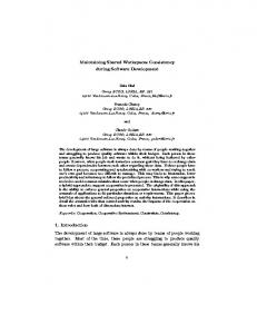
Modelica. Modelica-related stereotypes can be applied to SysML constructs to indicate their additional Modelica-specific semantics. All Modelica-related stereotypes are grouped into the SysML4Modelica profile. The part of the SysML model representing a Modelica model is called a SysML4Modelica model as shown in Figure 1. SysML Requirements
System Architecture (Structure)
Functions System Architecture (Dynamics) SysML4 Modelica
5.1
Advantages of Modeling Complete System Dynamics in SysML4Modelica
5.1.1 Staying in the same environment SysML4Modelica allows the modeler to stay in the same SysML modeling environment when describing both the high-level system aspects and the dynamic system behavior. A modeler then needs to add Modelica-specific stereotypes of SysML4Modelica profile to the SysML modeling constructs to describe a Modelica model in SysML. A Modelica class, for example, corresponds in SysML to the base level SysML block with a «ModelicaClass» stereotype applied to it. SysML4Modelica parts can finally be translated automatically into executable Modelica code.
5.1.2 Representing more graphical information Modelica
Figure 1. Relationship between Models in SysML, SysML4Modelica, and Modelica. In the context of the cooperation between the Georgia Institute of Technology and Siemens Corporate Technology, two implementations of the bidirectional SysML4Modelica-Modelica transformations were developed. The first implementation attempt was based on the QVT [20] standard for model transformations but could not be completed due to the absence of a bug-free QVT interpreter. The QVT implementation defined a model-to-model transformation. Since the Modelica metamodel is not standardized, a Modelica metamodel was chosen based on the metamodel of OpenModelica. A second Java-based prototypical implementation was developed to also take into account graphical model layout information. Since graphical layout information of SysML models is not standardized, maintaining this information requires a SysML tool-specific transformation. Therefore, our Java-based implementation used MagicDraw as a SysML modeling tool. The Java-based transformation was not a strict model-to-model transformation based on metamodels but a direct transformation between the Modelica concrete syntax and SysML.
5. MODELING SYSTEM DYNAMICS IN SYSML4MODELICA Some system requirements and functions are preferably validated with a dynamic system simulation. For this purpose, the dynamic system model can either be described in Modelica or in SysML4Modelica because both representations are semantically equivalent. A dynamic system model defined in SysML4Modelica can be automatically translated into Modelica code and vice versa. As a result, the modeler has to decide between defining the complete dynamic model in Modelica, in SysML4Modelica, or in a combination of both languages. Each approach has benefits and drawbacks. In any case, however, a SysML4Modelica model will be used to bridge the gap between high-level systems aspects defined in SysML and the executable dynamic system model described in Modelica. When developing the complete dynamic model in SysML4Modelica (e.g. to keep everything in one model for better management), the following advantages and challenges should be taken into consideration.
While most Modelica modeling tools support representation of component interactions similar to SysML internal block diagrams, SysML and thus, SysML4Modelica have other diagrams that can be used to represent additional information. For example, SysML block definition diagrams can describe relationships between different component types, SysML state charts and activity diagrams can specify the discrete and continuous behavior of components or subsystems, and SysML parametric diagrams can describe (Modelica) equations as well as other (combined system) constraints. Although the current SysML4Modelica standard only supports the representation of Modelica models with SysML internal block and block definition diagrams, the additional graphical SysML capabilities could eventually be used. As an additional example, SysML requirement diagrams can specify connections between Modelica components and the correspondding requirements.
5.1.3 Setting SysML4Modelica parts as invisible Since SysML4Modelica is not a new language but just an extension of SysML, Modelica-related stereotypes can be masked out by the SysML modeling tool. If the stereotypes are hidden, only the underlying SysML modeling constructs will be shown. This is advantageous for a system engineer who wants to gain an overview of the system model in SysML but who is not interested in the details that are necessary to describe an executable dynamic system model in Modelica.
5.2
Challenges of Modeling Complete System Dynamics in SysML4Modelica
It is important to note that the drawbacks listed in this section relate to the practice of modeling complete system dynamics in SysML4Modelica and not to the SysML4Modelica language itself.
5.2.1 Different structures and abstraction levels The degree to which the system architecture definition in SysML can be reused to describe the SysML4Modelica model has an impact on the modeling effort to create the dynamic system model in SysML4Modelica. If the SysML constructs describing the system architecture match the intended structure of the dynamic system model in SysML4Modelica, then the SysML constructs describing the system architecture can be reused to also describe the dynamic system model in SysML4Modelica. In this case, the SysML4Modelica model can be defined by only adding SysML4Modelica stereotypes to the existing SysML constructs. However, the component decomposition of the system architecture will most likely not match the component decomposition
of the dynamic model needed for simulation. While the component decomposition of the system architecture is intended to represent the main system components on a level of detail purely based on the modeler’s preference, the component decomposition of the SysML4Modelica model will be motivated by the reuse of existing Modelica components and by the need to define a dynamic system model that can be simulated without errors. The SysML4Modelica model will, for example, be composed of more modeling constructs than the system architecture model and of additional SysML constraints and connectors related to Modelica equations and algorithms. Since in this case the structure of the SysML4Modelica model is likely to be different than the system architecture defined in SysML, the SysML4Modelica model will have to be defined through new base level SysML constructs requiring additional modeling effort. Another drawback of combining abstraction levels is that the development of the detailed dynamics model requires different skills than high-level system architecture development. For example, a system architect knowing SysML may not be able to provide the complete and correct information for a detailed dynamic model. Similarly, a Modelica simulation expert may not be fluent in SysML. Nevertheless, because mapping of SysML constructs into Modelica constructs is often a one-to-many mapping, the modeler has to decide which SysML4Modelica stereotype has to be applied to a SysML construct. For example, a SysML block could either be a «ModelicaClass» or a «ModelicaBlock». A «ModelicaPort» stereotype could for example be uniquely applied to a SysML port. However, users would still be required to manually complete the definition of the Modelica port through the properties of the «ModelicaPort» stereotype.
5.2.2 Debugging with graphical visualization An important aspect to consider when modeling a dynamic system model is debugging. The definition of a dynamic system model often contains errors by being either under- or over-determined, or by having wrong values. Most SysML modeling tools do not provide off-the-shelf checking and debugging capabilities as Modelica modeling tools do. Therefore, the only way to efficiently track down and resolve errors in a SysML4Modelica model is to translate it into the corresponding Modelica model and to open and simulate it with a Modelica modeling tool. Furthermore, the graphical visualization of simulation results is an important feature for efficient analysis. The simulation results shown as graphs allow quick and simple validation of a dynamic system model. Most Modelica modeling tools provide plotting capabilities in order to easily see the value of the system states during a simulation run. This information is important as several system parameters are typically fine-tuned during such analysis.
5.2.3 Iterative development In general, it is more efficient to resolve bugs in a dynamic system model iteratively (for example by going through several small and manageable modeling and testing phases) rather than sequentially by modeling the entire model and then testing the entire model with all its errors. This means that a modeler who wants to follow the efficient iterative development method and to define a dynamic system model in SysML4Modelica would have to translate it into Modelica, test it with a Modelica modeling tool, and adapt the model in SysML4Modelica in many iterations. Having to often switch between two different dynamic system representations and two different modeling tools to define and test a dynamic system model is cumbersome.
5.3 Mixed-Paradigm Approach To overcome the identified challenges while taking advantage of the identified benefits, we propose a “mixed-paradigm” approach whereby instead of exclusively using SysML4Modelica, we use a combination of SysML, SysML4Modelica, and Modelica for the different phases of mechatronic design. In the proposed workflow, only the high-level dynamic structure and interfaces are defined in SysML4Modelica and the detailed dynamic behavior is defined in Modelica. These are the proposed steps: 1. 2.
3. 4.
5. 6.
7. 8.
Definition of high-level system aspects including requirements, use cases and functions in SysML Definition of the high-level structure of system architecture in SysML. Definition of the high-level dynamic system model including components, component interfaces and interactions in SysML (Partial) definition of dynamic models in SysML4Modelica for components intended to be implemented in Modelica. Definition of dependencies between the dynamic system model components and the structure of the architecture model in SysML Translation of the provided SysML4Modelica subsystem into Modelica Completion of the dynamic model components in Modelica by adding the missing behavior, followed by simulations, and the analysis of simulation results Translation of the complete dynamic system model from Modelica into SysML4Modelica Definition of additional dependencies between dynamic system model components and high-level system aspects in SysML, among others: traces from the detailed dynamic model to the requirements, test cases etc.
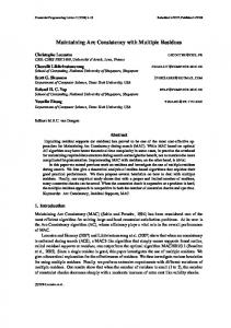
Figure 2 shows how the proposed approach can be applied to the model of the electrical vehicle (eCar) described in [8]. The different steps and experienced benefits are explained below in more detail. Step #1 and Step #2 SysML is used to define high-level system aspects such as requirements, functions, use cases (Step #1), and the system architecture (Step #2). Requirements related to the eCar may, for example, impose a remaining minimum battery state of charge after a specified driving cycle. The system architecture of the eCar is composed of the main components including the driver, electric motor, cruise control, environment, and others. Since modelers like to use their language of preference, it is very likely that components of a large dynamic system model will be defined in different languages. Many modeling or programming languages including Modelica, Simulink, FORTRAN, and C can be used to describe various components of a large dynamic system model. SysML can be used as a neutral representation for defining the structure of a large dynamic system model whose components are intended to be implemented in different languages. In this case, interfaces of components need to be clearly defined in order to be compatible with each other. Since SysML is language- and vendor-neutral, it can be used to define interfaces and interactions of dynamic system model components. Thus, the SysML model can be seen as a contract which various component modelers need to be in compliance with in order to ensure component compatibility.
Step # 3 If some dynamic system model components are intended to be transformed to Modelica, they are distinguished by applying SysML4Modelica stereotypes. In this case, the definition of blackbox components is not as error-prone as the definition of the internal component behavior in SysML4Modelica. Instead, the detailed internal component behavior can be specified in a Modelica environment and the definition of interfaces and interactions between components can be defined in SysML4Modelica.
Requirements
Use cases
Step #4
System Architecture SysML Modeling Environment
An important advantage of defining the structure of a dynamic system model in SysML/SysML4Modelica is the fact that dependencies between the system architecture model and the dynamic system model can be formally defined in SysML (Step #4). Both models will share common properties as well as, to a certain degree, a common structure. For example, the number of moveable system components defined in the system architecture will be reflected in the dynamic system model. Similarly, the inertial properties of the moveable system components such as the mass and moment of inertia defined in the system architecture will also be defined redundantly in the dynamic system model. Consequently, for Step #4 it is important to formally define interfaces between all components and the dependencies between them in order to enable an efficient and unambiguous communication between system engineers and dynamic system specialists. A system engineer can then easily see how a change in the system architecture will affect the dynamic system model, and a dynamic system specialist can trace back features of the dynamic system model to the system architecture aspects such as requirements, test cases, and system structure. In addition, the formally defined dependencies can also support the automatic propagation of values from one model to the other in order to efficiently ensure automatic model consistency. The dependencies can be expressed in SysML through various SysML concepts including allocation, generalization, redefinition, association blocks, and parametric diagrams. For example, a SysML constraint can express the equality condition between the mass property of the vehicle situated redundantly in the system architecture and in the dynamic system model.
2
2
The definition of the dynamic system model components can be completed in a Modelica modeling environment by adding more details (Step #6). This supports the efficient debugging capabilities of a Modelica modeling environment and mitigates the problem of the lack of debugging in SysML (see Section 5.2.2).
8
3
3
5 Dynamic System Model in Modelica
Modeica Modeling Environment
Step #6, Step #7 and Step #8
4
Dynamic System Model in SysML4Modelica
Step #5 As a next step, partially defined components in SysML4Modelica are automatically translated into Modelica code. This ensures that the component interfaces defined in SysML4Modelica are identical with the ones used in Modelica and it avoids the timeconsuming and error-prone manual redefinition of component interfaces in Modelica. Moreover, problems related to different structures and abstraction levels (see Section 5.2.1) can be avoided to a certain degree.
1
Function Trees
7
6
Figure 2. Mixed-paradigm approach for mechatronic design in SysML, SysML4Modelica, and Modelica
In addition, the drawbacks of an interactive development approach (see Section 5.2.3) are diminished. The fully defined and analyzed dynamic system model can then be translated back into SysML4Modelica (Step #7) in order to allow the definition of additional dependencies between the dynamic system model and other system aspects such as requirements, functions, and system architecture (Step #8).
6. CONCLUSION Traditionally, systems engineering aspects and system dynamics are described in different modeling languages e.g. SysML and Modelica. As a result, the system architecture model is decoupled from the dynamic system model and the risk of inconsistencies is high. A model that is not up to date may increase the likelihood of miscommunication among engineers and may lead to wrong design decisions. In this paper, we present how SysML4Modelica can be used to efficiently bridge the gap between high-level system aspects defined in SysML and dynamic system models defined in Modelica. An analysis of the advantages and challenges of modeling a dynamic system model entirely in SysML4Modelica has been presented. In this case the advantages of SysML4Modelica are its capabilities for extended graphical representation and the traceability between all aspects defined in SysML. On the other hand, the main disadvantage when developing the complete dynamics in SysML4Modelica is the combination of the abstraction levels that makes its development unmanageable. To overcome this and other problems, our recent experiences show that it is more efficient to define the detailed dynamic system model in Modelica instead of SysML4Modelica. Taking into account both the modeling effort and the need to maintain consistency between high-level system architecture and a dynamic system model, a mixed-paradigm approach combining SysML, SysML4Modelica and Modelica has been proposed. Our future work will be focused on a better integration of SysML4Modelica with SysML and Modelica to enable the application of this technology in large industrial projects.
7. ACKNOWLEDGMENTS This work has been funded by Siemens Corporate Technology in the context of the Siemens internal research project LHP MDE (Light House Project - Mechatronic Design). The authors would like to thank Wladimir Schamai, Adeel Asghar, Adrian Pop and Peter Fritzson for providing support for OpenModelica as well as Roland Samlaus for sharing with us his XText-based Modelica grammar.
8. REFERENCES [1] OMG, OMG Systems Modeling Language (OMG SysML) Version 1.2, 2010: http://www.omg.org/spec/SysML/1.2/. [2] Spangelo, S.C., et al., Applying Model Based Systems Engineering (MBSE) to a standard CubeSat, in IEEE Aerospace Conference, 2012 [3] Karban, R., et al., Exploring Model Based Engineering for Large Telescopes - Getting started with descriptive models, in SPIE Astronomical Telescopes and Instrumentation, 2008. [4] Wu, D., et al., SysML-based design chain information modeling for variety management in production reconfiguration. J Intell Manuf, 2011: p. 1-22.
[5] OMG, OMG Unified Modeling Language (OMG UML), Superstructure Version 2.4.1, 2011: http://www.omg.org/spec/UML/2.4.1/. [6] Modelica Association, Modelica Specification, version 3.2, 2010: https://modelica.org/association. [7] Shah, A.A., D. Schaefer, and C.J.J. Paredis, Enabling MultiView Modeling With SysML Profiles and Model Transformations, in International Conference on Product Lifecycle Management, 2009. [8] Votintseva, A., P. Witschel, and A. Goedecke, Analysis of a Complex System for Electrical Mobility Using a ModelBased Engineering Approach Focusing on Simulation. Procedia Computer Science, 2011. 6: p. 57-62. [9] OMG, SysML-Modelica Transformation (SyM), V1.0, Beta 3, 2012, http://www.omg.org/spec/SyM/Current [10] Pop, A., D. Akhvlediani, and P. Fritzson, Towards Unified Systems Modeling with the ModelicaML UML Profile, in International Workshop on Equation-Based Object-Oriented Languages and Tools. 2007. [11] Schamai, W., et al., Towards Unified System Modeling and Simulation with ModelicaML: Modeling of Executable Behavior Using Graphical Notations, in 7th Modelica Conference, 2009. [12] Nytsch-Geusen, C., The use of the UML within the modelling process of Modelica-models, in Proceedings of EOOLT, 2007. [13] Ji, H., Lenord O., and D. Schramm, A Model Driven Approach for Requirements Engineering of Industrial Automation Systems, in Proceedings of the 4th International Workshop on Equation-Based Object-Oriented Modeling Languages and Tools, Zurich, Switzerland, 2011. [14] Johnson, T., C.J.J. Paredis, and R. Burkhart, Integrating models and simulations of continuous dynamics into SysML, in Modelica Conference, 2008. [15] Paredis C.J.J., et al., An Overview of the SysML-Modelica Transformation Specification, in INCOSE International Symposium, 2010. [16] Vasaiely, P., Interactive Simulation of SysML Models using Modelica, 2009, Hamburg University of Applied Sciences. [17] Plateaux, R., et al., Integrated design methodology of a mechatronic system. Mécanique & Industries, 2010. 11: p. 401-406. [18] Friedenthal S., Moore A., and Steiner R., A Practical Guide to SysML: The Systems Modeling Language, 2009: Morgan Kaufmann. [19] Weilkiens, T., Systems Engineering with SysML/UML: Modeling, Analysis, Design, 2008: Morgan Kaufmann [20] OMG, Meta Object Facility (MOF) 2.0 Query/View/ Transformation Specification, V1.1, January 2011, http://www.omg.org/spec/QVT/Current