with little e ort, practical 3D texture mapping in software/hardware rendering systems, including the 3D real-time graphics APIs like OpenGL and Direct3D.
Making 3D Textures Practical
Chandrajit Bajaj Department of Computer Sciences The University of Texas at Austin U.S.A.
Insung Ihm Sanghun Park Department of Computer Science Sogang University Seoul, Korea
Abstract
While 2D texture mapping is one of the most powerful rendering techniques that make 3D objects appear visually interesting, it su�ers from the visual artifacts, produced when 2D image patterns are wrapped onto the surface of objects with arbitrary shapes. On the other hand, 3D texture mapping generates highly natural visual e�ects in which objects appear carved from lumps of materials rather than laminated with thin sheets as in 2D texture mapping. Storing 3D texture images in a table for fast mapping computations, instead of evaluating procedures on the y, however, has been considered impractical due to the extremely high memory requirements. In this paper, we present a new e�ective method for 3D texture mapping, designed for real-time rendering of polygonal models. Our scheme attempts to resolve the potential texture memory problem arising from the very large size of 3D images by compressing them using an e�ective encoding method. The experimental results on various non-trivial 3D textures and polygonal models show that high compression rates are achieved with few visual artifacts in the rendered image and a small impact on rendering time. The simplicity of our compression-based scheme will make it possible to implement, with little e�ort, practical 3D texture mapping in software/hardware rendering systems, including the 3D real-time graphics APIs like OpenGL and Direct3D.
1 Introduction Texture mapping is one of the most powerful rendering techniques that make three-dimensional objects appear visually more complex and realistic [6]. Two-dimensional texture mapping has been popular in creating many interesting visual e�ects by projecting or wrapping 2D image patterns onto the surface of solid objects. While it has proved very useful in adding realism in rendering, 2D texture mapping su�ers from the limitation that it is often di�cult to wrap 2D patterns, without visual artifacts, onto the surface of objects having complicated shapes. As an attempt to alleviate the computational complications of wrapping as well as to resolve the visual artifacts, Peachey [12] and Perlin [13] presented the use of space lling 3D texture images, called solid textures. Many of the textures found in nature such as wood, marble, and gases, are easily simulated with solid textures that map three-dimensional object space to color space [3]. Unlike the 2D textures, they exist not only on the surface of objects but also inside the objects. Texture colors are assigned to any point of the entire solid object simply by evaluating the speci ed functions or codes according to their positions in 3D space. The 3D solid texture mapping can be viewed as immersing geometric objects in virtual volumes associated with 3D textures, and getting necessary texture colors from the solid textures. This 3D texture mapping produces highly natural visual e�ects in which objects appear carved from lumps of materials rather than laminated on the surfaces as in 2D texture mapping. The di�erence between 2D and 3D mapping is prominent particularly when objects have complicated geometry and
topology since 3D textures are not visually a�ected by the distortions that exist in object parameter space. Many useful 3D textures are generally synthesized procedurally instead of painting or digitizing them (Refer to [3] for several interesting examples.). They are based on mathematical functions or programs that take 3D coordinates of points as input, and compute their corresponding texture values. The evaluation is usually carried out on the y during the rendering computation. While procedural texture models provide a very compact representation, evaluating procedural textures as necessary during texture mapping leads to slower rendering than accessing pre-sampled textures stored in simple arrays. While using sampled 3D texture maps in 3D volumetric form is faster, they tend to take up a large amount of texture memory. For example, a 3D texture has the resolution 256 � 256 � 256, its RGB texture requires 48 Mbytes of texture memory. Although some recent graphics systems allow the use of main memory for textures, such memory costs are an impossible burden on most current graphics systems. Storing several elaborate textures with high resolution, say, 512 � 512 � 512 would be prohibitive even to the most advanced rendering systems. Obviously, there is a tradeo� between the size of texture memory and the computation time. Explicitly storing sampled textures in dedicated memory, and fetching texture colors as necessary, as in the current graphics accelerator supporting real-time texture mapping, can generate images faster than evaluating them on the y. To make this feasible for 3D texture mapping, however, e�cient solutions for manipulating potentially huge textures e�ectively need to be devised. This paper presents a new and practical scheme for real-time 3D texture mapping which is easily implemented. Our technique relies on 3D volume compression and processing from compressed solid textures. The idea of rendering directly from compressed textures has been presented in the past by [2], where they used vector quantization to compress 2D textures in simple or mip-map form. To compress 3D textures, we use a wavelet-based compression method that provides fast decoding to random data access, as well as fairly high compression rates [1]. This compression technique exploits the power of wavelet theory and naturally provides multi-resolution representations of 3D RGB volumes. With this compression method, we can store mip-maps for 3D textures of non-trivial resolutions very compactly in texture memory. Its fast random access decoding ability also results in only a small impact on rendering time. The simplicity of our new 3D texture mapping scheme makes it easy to implement in software/hardware rendering systems. Furthermore, 3D real-time graphics APIs like OpenGL and Direct3D can be extended with little e�ort to include 3D texture mapping without heavy demand for very large texture memories. The rest of this paper is organized as follows: In Section 2, we provide a detailed description of the new texture mapping technique. Experimental results on various 3D textures and polygonal objects are reported in Section 3. Finally, we present conclusions and directions for further research in Section 4.
2 A New 3D Texture Mapping Scheme In this section, we describe a new 3D texture mapping method suitable for real-time rendering of polygonal models. The idea presented here can also be used e�ectively in other rendering systems such as RenderMan [14] to enhance the texture mapping speed. The key point in our texture mapping scheme is to extract only the necessary portion from the whole 3D texture map, then compress it in compact form where fast run-time decoding for random access to texel values is possible. In particular, the compression method we apply is based on wavelet theory, and naturally supports multi-resolution representations of 3D textures. This capability of the compression method makes it easy to construct 2
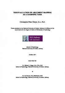
Polygonal Model
Subsection 2.1
3D Texture Map
3D Texture Modeling Polygonal Model with 3D Texture
Subsection 2.2
3D Texture Cell Selection Polygonal Model with Selected 3D Texture Cells
Subsection 2.3
3D Texture Compression Polygonal Model with Compressed 3D Texture
Subsection 2.4
Polygonal Rendering 3D Textured Image
Figure 1: 3D Texture Mapping Pipeline 3
a 3D texture mip-map using a small amount of texture memory. Figure 1 illustrates the 3D texture mapping pipeline in which the rst three steps 3D Texture Modeling, 3D Texture Cell Selection, and 3D Texture Compression comprise the necessary pre-processing stages. In the following subsections, we provide a detailed explanation of the pipeline.
2.1 3D Texture Modeling
Our scheme assumes, as an input texture, a sampled 3D texture stored in a 3D array. It is generated by sampling texel values from a three-dimensional texture eld that is usually described proceduarlly. The storage requirements are very high for uncompressed 3D texture maps at reasonable resolution: 2563 and 5123 RGB textures need 48 Mbytes and 384 Mbytes, respectively. This is one of the reasons which make fast 3D texture mapping with stored textures appear impractical. In the texture modeling stage, a polygonal object in its object space Ros = f(x; y; z ) j x; y; and z are realg is textured by putting it in a 3D texture de ned in the texture space Rts = f(s; t; r) j 0 � s; t; r � 1g, and nding the intersection of the object's surface and the texture. Texturing an object can be viewed as nding a function f : Ros ?! Rts . The function map can be arbitrary.
2.2 3D Texture Cell Selection
Once a mapping between a polygonal object and 3D texture is xed, the unnecessary texture data is eliminated to reduce storage space. Consider an ns � nt � nr texture. In our scheme, the texture data is subdivided into small subblocks of size nc � nc � nc, called texture cells (In our current implementation, the texture cell size is 4 � 4 � 4.). A texture cell is a basic unit for selecting texture data that is actually needed for rendering. In this 3D texture cell selection stage, each polygon comprising of the boundary of an object is 3D scan-converted to nd all the texture cells that intersect with the surface of the solid object. Notice that texels in the selected texture cells contain all the texture information necessary for rendering. The cells that are not chosen are replaced by null cells, that is, cells with black colors. By keeping nearby texels surrounding the surface of an object in this intermediate stage, a large portion of texture data is removed to alleviate the potential prohibitive storage requirement. The selected texture cells take only a small percentage of the original texture data. The null cells still exist in the texture map in this stage, and the texture size remains the same. However, the spatial coherence created by null cells makes an encoding scheme e�ciently compress the 3D texture in compact form in the next stage.
2.3 3D Texture Compression
2.3.1 Choosing an Appropriate Compression Technique
There exist many data compression methods for e�cient storage and transmission. It is very important to choose a compression technique which is the most appropriate for this speci c 3D texture mapping application. We have several similar issues to consider as described in [9, 2]: 1. High compression rate and visual delity. Non-trivial 3D textures are often very large in size, ranging a few dozen megabytes to several hundred megabytes. When a mip-map is used for a pre- ltered multi-resolution representation, the size get even larger. Developing real-time applications with such data assumes, implicitly or explicitly, that the entire data is loaded into main memory for e�cient run-time processing. This places an enormous burden on storage space as well as transmission bandwidth. While lossless compression techniques preserve data without introducing reconstruction errors, they often fail to achieve compression rates high 4
2.
3.
4.
5.
enough for practical implementation of 3D texture mapping. The loss of information associated with lossy compression methods, however, needs to be controlled as it is important to minimize the distortion in the reconstructed textures. Fast decoding for random access. The general concern of most lossy compression schemes is achieving the best compression rate with minimal distortion in the reconstructed images [5, 15]. Such compression methods, however, often impose constraints on the random access decoding ability, which makes them inappropriate for interactive texture mapping applications especially where it is di�cult to predict data access patterns in advance. For instance, variable-bitrate or di�erential encoding schemes such as Hu�man or arithmetic coders coupled to block JPEG or MPEG schemes, do not lend themselves to e�ciently decode individual texels that are accessed in a random pattern during run-time. Multi-resolution representation. Mip-mapping is the most commonly used anti-aliasing technique for 2D texture mapping [18]. A mip-map of a 2D texture is a pyramid of pre- ltered images obtained by averaging down the original image to successively lower resolutions. Mipmapping with this level-of-detail representations of textures o�ers fast and constant ltering of texels, and its simplicity lends itself to an e�cient hardware implementation. The idea naturally extends to 3D textures although they have regarded it as impractical due to the memory requirements. It is highly recommended to choose a compression technique that provides a multi-resolution representation in its compression scheme. Exploitation of 3D data redundancy. 3D textures are three-dimensional data that exhibit redundancy in all three dimensions. A compression scheme devised for 2D images could be applied to compress each slice in 3D textures, however, a good compression technique must be able to fully exploit data coherence in all dimensions to maximize the compression performance. Compression block by block. In some applications like ours, it is more e�cient to selectively compress a certain portion of data rather than the entire one. It is very desirable that a compression scheme include this selective compression capability in its encoding algorithm for e�ective compression.
2.3.2 The Zerobit Encoding Scheme The above ve desirable characteristics are common to most real-time applications that must handle discrete sampled data of very large sizes. Vector quantization has been popular in developing such applications mainly because it supports fast random decoding through table lookups [4]. Some applications of vector quantization in the computer graphics eld, include compression of CT/MRI datasets [10], light elds [9], and 2D textures [2]. Recently, a new compression scheme for 3D RGB image has been developed as an alternative to vector quantization [1]. This technique, called zerobit encoding, is suitable for applications wherein data are accessed in an unpredictable manner, and real-time performance of decoding is required. It extends the compression scheme [7, 8] for 3D gray-scale volume data to compression of 3D RGB images, and its new encoding structure signi cantly improves the decompression speeds. Unlike vector quantization, the zerobit encoding scheme, based on the wavelet theory, naturally o�ers a multi-resolution representation for 3D images. Experimental results on test data sets show that this compression scheme provides fast random access to compressed data in addition to achieve fairly high compression rates. The basic compression unit for the technique is a 4 � 4 � 4 subimage, called cell, to which the 3D Haar tranform is applied twice to exploit data coherence in three dimensions. Once compressed, three levels 5
of detail are represented in compressed form. Notice that the texture cell in our 3D texture mapping scheme naturally corresponds to the cell in this compression technique. Figure 2 shows a sample statistics on the performances of the zerobit encoding and vector quantization used in [9] for two representative light eld datasets budda and dragon whose resolutions are 32 � 32 � 256 � 256 (192MBytes) [1]. To use the zerobit encoding technique, 4D sampled light eld datasets were reformulated into 3D images, then compressed. While the vector quantization yielded compression rates 21.79 and 20.18 for budda and dragon, the zerobit encoding method produced higher rates of 44.51 to 91.11 and 38.21 to 83.03 at the selected four target ratios, respectively (Figure 2(a)) 1 . The PSNR data shows that the reconstructed image quality is almost the same when about 2% and 5% of coe�cients are used in zerobit encoding for the budda and dragon datasets, respectively (Figure 2(c) and (d)). For the timing performance, the image-based rendering time, spent on displaying 76 frames of 382 � 382 pixels with gradually varying viewing parameters, was measured on SGI 195 MHz R10000 CPU. Two cases of bilinear interpolation on the st-plane (st-lerp) and quadralinear interpolation on both uv- and st-planes (uvst-lerp) were tested (Figure 2(b)). The timing results show the zerobit encoding scheme is faster for both datasets in most cases. Note that the reconstruction cost per data item for vector quantization is very cheap since decompression is performed through a simple codebook lookup. It must be cheaper than zerobit encoding on the average. However, zerobit encoding decompresses several data items, 4 planes in this case, at the same time, and is very quick particularly when data in empty background regions are reconstructed, which results in faster rendering on the whole. When nearest samples without interpolation are taken during image-based rendering, the zerobit encoding method yielded frame rates 39 and 52 for the two datasets. While the empirical comparisons for a few applications cannot prove that the zerobit encoding is always superior to vector quantization, we nd the former compares very favorably to the latter. In our 3D texture mapping technique, we use the zerobit encoding scheme to compress the selected texture cells. As will be explained in the next section, it also proves to be very e�ective in compressing 3D textures.
2.4 Polygonal Rendering with Compressed Textures 2.4.1 A New Capability for OpenGL 1.2
During applying textures to geometric objects, the necessary texel values are repeatedly fetched from zerobit-encoded 3D textures using their texture coordinates. This compression-based 3D texture mapping could be also used to enhance the rendering speed in a time-consuming rendering system that produces photo-realistic images. In our implementation, however, we extended the OpenGL library to include the feature of texture mapping from encoded 3D textures. 3D texture mapping has been implemented as a feature of the OpenGL 1.1 extensions, and is now one of the core capabilities that must be supported by all OpenGL 1.2 implementations [16]. The glTexImage1D() and glTexImage2D() functions are extended for 3D texture mapping where the command for specifying a three-dimensional texture image is de ned as void glTexImage3D (GLenum target, GLint level, GLint internalformat, GLsizei width, GLsizei height, GLsizei depth, GLint border, GLenum format, GLenum type, void *data); With the target GL TEXTURE 3D, this command reads a texture of size width � height � depth, that is stored in memory, pointed by data, in the format of internalformat. For a compressed texture, our 1
These rates exclude the gzip compression, that could follow both compression methods for e�cient storage as in [9].
6
Size (MB) Comp. Rate PSNR (dB) dragon Size (MB) Comp. Rate PSNR (dB) budda
Vector Quantization 8.81 21.79 38.00 9.52 20.18 35.58
2.0% 2.11 91.11 39.26 2.31 83.03 31.00
Zerobit Encoding 3.0% 4.0% 5.0% 2.90 3.63 4.31 66.26 52.89 44.51 41.70 43.63 45.18 3.15 4.09 5.02 60.87 46.99 38.21 32.17 33.37 34.40
(a) Compression Rate and Quality
Vector Quantization 8.03 budda st-lerp uvst-lerp 28.39 4.33 dragon st-lerp uvst-lerp 13.42
2.0% 5.59 25.42 3.09 13.23
Zerobit Encoding 3.0% 4.0% 5.0% 5.59 5.59 5.59 25.47 25.52 25.52 3.11 3.14 3.17 13.32 13.43 13.53
(b) Rendering Time (Seconds/76 Frames)
(c) Vector Quantization (budda)
(d) 3% of Coe�cients (budda)
Figure 2: Comparisons with Vector Quantization on Light Field Datasets [1]
7
extension uses GL UNSIGNED BYTE COMPRESSED for type to read a compressed texture, whose texels are stored in unsigned character, on levels level, level+1, and level+2. When 3D texture mapping is enabled by calling glEnable(GL TEXTURE 3D), and a compressed 3D texture is speci ed, the texture is assumed to be in compressed form, and texels are fetched from the zerobit-encoded structure rather than a simple array. The extension is just clear and easy to implement since the new capability can be included simply by adding proper state variables and decoding functions. Other utility functions, such as creating encoded 3D textures with user-speci ed compression rates, could be included in the OpenGL Utility Library (GLU).
2.4.2 Compact Representations of 3D Mip-Maps
A 3D mip-map is an ordered set of 3D arrays representing the same texture where each array has a resolution lower than the previous one. Currently, we are implementing the 3D mip-map capability so that mip-maps as well as single 3D textures are represented very compactly. Given a base 3D texture, the zerobit-encoded structure represents three levels of detail with level number 0, 1, and 2. Then the reduction images on the next three levels can be stored in another zerobit-encoded structure. An alternative is to store the texture images with lower resolutions except the level 0, 1, and 2 images, in simple 3D arrays. The images on the higher levels take up a small amount of storage. For example, when a 256 � 256 � 256 RGBA image in unsigned character is loaded, the entire reduced images on levels 3; 4; � � � ; 8 require only 256 Kbytes in total.
2.5 Sharing a 3D Texture by Multiple Objects
In our current implementation, only the 3D texture cells surrounding the surface of a polygonal object are selected then compressed. When a texture is compressed object by object, it could lead to a waste of texture memory. That is, if a 3D image is shared by multiple polygonal objects, the same 3D texture cells can be replicated for several objects. We plan to support three types of compression mode: The rst mode, called zerobit encoding single object is one we have described in this article. The second mode zerobit encoding multiple objects is for the case in which several polygonal objects share a 3D texture. In this mode, all the 3D texture cells that are used by at least one object are selected before encoding. This shared mode allows an e�cient representation of compressed textures. The last mode zerobit encoding entire texture handles the dynamic situation in which it is hard or impossible to predict which texture cells to be used for rendering. For instance, an interesting animation can be generated by making an object oat in a texture eld, dynamically binding texture coordinates. In this case, the rst two compression modes are not appropriate. The third mode compresses the entire 3D texture and load it for rendering. While it is the most expensive, this mode provides a exibility in texture mapping.
3 Experimental Results We have implemented our new 3D texture mapping scheme by extending the MESA 3D Graphics Library which is an OpenGL implementation, publicly available at [11]. The current version 3.0 supports the 3D texture mapping feature where the entire texture image is stored in a simple array without any compression. We added the necessary state variables and functions to handle zerobitencoded 3D texture maps. We have generated four di�erent 3D textures of size 256 � 256 � 256 (Figure 3). The texture images have three channel RGB colors, and their sizes amount to 48 Mbytes, respectively. The three textures Bmarble, Wood, and Eroded were created using the RenderMan surface shaders blue marble(), 8
(a) Bmarble
(b) Gmarbpol
(c) Wood
(d) Eroded
Figure 3: Sample Slices from the Four Example 3D Textures wood(),
and eroded(), respectively [17]. The surface shader gmarbtile polish() for the texture Gmarbpol were written by Larry Gritz, and is available as a part of the Blue Moon Rendering Tools (BMRT). Our technique have been applied to polygonal models with various sizes, including those listed in Table 1. The teapot model Teapot was polygonized from a parametric equation. The next two models Dragon and Bunny were obtained from Viewpoint and the Stanford 3D Scanning Repository, respectively. The last model Head was created by nding an iso-surface from the UNC CT scan of a human head. The table shows how many 4 � 4 � 4 texture cells are selected from the entire 262,144 (= 64 � 64 � 64) cells in 256 � 256 � 256 textures through the 3D texture cell selection stage after texture modeling. We observe that the ratios of selected cells are quite small. To nd out how compactly these 3D textures can be associated with the polygonal objects, we # of Faces # of Selected Cells Ratio (%) Teapot 1,152 6,761 2.6 Dragon 12,078 7,083 2.7 Bunny 69,451 14,551 5.6 Head 203,544 31,122 11.9 Table 1: Ratios of Selected Texture Cells 9
compressed selected texture cells for the entire 16 combinations as shown in Table 2. In the zerobit encoding scheme, a user speci es a ratio of wavelet coe�cients to be used after truncation to control the degree of compression [1]. This gure, shown in the \Target Ratio" eld, represents an approximate ratio of wavelet coe�cients that are actually used in encoding. We compressed 3D textures at three target ratios 3%, 5%, and 10%, and rendered the polygonal objects from the compressed textures. In the table, we compare sizes and compression rates for various cases. Observe that it took less than 1 Mbytes of memory for all combinations, ranging from 172 Kbytes to 804 Kbytes. Considering that the size of the original textures is 48 Mbytes, we see that very high compression rates are achieved through the zerobit encoding. Figure 4 shows sample images rendered with the linear lter GL LINEAR from the compressed textures having desired ratio 10%. When the 3D textures are compressed with a desired ratio higher than 10%, the texture-mapped images, produced with the linear lter, are almost free of aliasing artifacts which are caused by the loss of information during compressing 3D textures. In Figure 5, we enlarged a portion of the Bunny images to make the compression artifacts more visible. When the ratio is 3%, the blocky artifacts are clearly visible, but most features are still preserved well enough for many real-time applications such as 3D games and animation. In order to check the timing performance, we measured the running times, spent on rendering 54 frames of 512 � 512 pixels with incrementally varying viewing parameters. They include all computations for rendering including 3D texture mapping, viewing parameter setting, and image displaying. The timings were measured on an SGI Octane workstation with 195 MHz R10000 CPU and 256 Mbytes of memory without hardware graphics acceleration. Table 3 reports the average time per frame in seconds for three di�erence rendering modes. The \Gouraud Shading Only" eld in the table is the time taken for rendering the objects using Gouraud shading only, and indicates how complicated a rendering is involved. Then, our new compression-based scheme was compared with texture mapping without compression to evaluate overheads for fetching texels from compressed textures. Two ltering methods GL NEAREST and GL LINEAR were tested. The running time is proportional to the number of pixels that objects are projected into. As indicated by the test results, the zerobit encoding method provides very fast decoding speeds. We observe only a 14 percent and a 15 percent impact on rendering time on the average for the nearest and the linear lter, respectively. Notice that the linear ltering method takes, for instance, 0.37 second to render Teapot from its uncompressed texture of size 48 Mbytes. On the other hand, the same ltering takes 0.44 second to produce a Teapot image with few visual artifacts from its compressed texture of size 268 KBytes (target ratio = 10%). The bene t from our compression-based 3D texture mapping is evident, and is critical in particular when the resource for texture memory is rather limited. We have also generated two more elaborate textures of 512 � 512 � 512 whose size is 384 Mbytes, and tested our texture mapping scheme with these huge textures (Table 4). The experiments indicate that 500 Kbytes to 1.61 Mbytes of memory is required to store the textures compressed at the target ratios 3%, 5%, and 10%, achieving the compression rates of 238.0 : 1 to 786.4 : 1. Compared to the 2563 textures, compression-based renderings take 1.26 (Teapot with Bmarble) and 1.09 (Head with Gmarbpol) times as long on the average for the 5123 textures. We were not able to load the entire uncompressed textures for rendering onto our workstation with 256 Mbytes of main memory, but 10
Texture
Object Target Ratio Size (KB) Comp. Rate 3% 188 261.5 : 1 Teapot 5% 224 219.4 : 1 10% 268 183.4 : 1 3% 188 261.5 : 1 Dragon 5% 216 227.6 : 1 Bmarble 10% 272 180.7 : 1 2563 3% 272 180.7 : 1 Bunny 5% 340 144.6 : 1 10% 468 105.0 : 1 3% 380 129.4 : 1 Head 5% 488 100.7 : 1 10% 712 69.0 : 1 3% 188 261.4 : 1 Teapot 5% 204 240.9 : 1 10% 232 211.9 : 1 3% 172 285.8 : 1 Dragon 5% 192 256.0 : 1 Gmarbpol 10% 228 215.6 : 1 2563 3% 244 201.4 : 1 Bunny 5% 284 173.1 : 1 10% 336 146.3 : 1 3% 332 148.1 : 1 Head 5% 420 117.0 : 1 10% 540 91.0 : 1 3% 192 256.0 : 1 Teapot 5% 224 219.4 : 1 10% 304 161.7 : 1 3% 192 256.0 : 1 Dragon 5% 232 211.9 : 1 Wood 10% 308 159.6 : 1 2563 3% 288 170.7 : 1 Bunny 5% 372 132.1 : 1 10% 524 93.8 : 1 3% 388 126.7 : 1 Head 5% 524 93.8 : 1 10% 804 61.1 : 1 3% 188 261.5 : 1 Teapot 5% 224 219.4 : 1 10% 288 170.7 : 1 3% 192 256.0 : 1 Dragon 5% 232 211.9 : 1 Eroded 10% 288 170.7 : 1 2563 3% 280 175.5 : 1 Bunny 5% 356 138.1 : 1 10% 492 99.9 : 1 3% 384 128.0 : 1 Head 5% 516 95.3 : 1 10% 768 64.0 : 1
Table 2: Size of Compressed Textures 11
(a) Teapot with Bmarble
(b) Dragon with Wood
(c) Bunny with Eroded
(d) Head with Gmarbpol
Figure 4: Images Rendered with GL LINEAR from Compressed Textures (10%)
12
(a) Uncompressed
(b) Compressed (10%)
(c) Compressed (5%)
(d) Compressed (3%)
Figure 5: Aliasing Artifacts of Compression-Based 3D Texture Mapping
13
Target Gouraud Shading 3D Texture 3D Texture Ratio Only Mapping (Nearest) Mapping (Linear) uncompressed 0.05 0.13 0.37 Teapot 3% { 0.14 0.42 with Bmarble 5% { 0.15 0.43 10% { 0.16 0.44 uncompressed 0.26 0.45 0.89 Dragon 3% { 0.50 0.98 with Wood 5% { 0.52 1.00 10% { 0.55 1.04 uncompressed 1.03 1.39 1.77 Bunny 3% { 1.56 2.04 with Eroded 5% { 1.60 2.13 10% { 1.66 2.21 uncompressed 2.87 3.68 4.51 Head 3% { 3.89 4.85 with Gmarbpol 5% { 3.94 4.90 10% { 4.00 5.03
Table 3: Rendering Time Per Frame (Seconds) expect that the rendering times will also get slower at the same rate. Figure 6 makes a comparison between renderings with four di�erent texture mapping parameters. When Teapot is rendered from the 5123 texture with a target ratio of 10% and the linear lter ((b)), the texture pattern on the surface appears much clearer than in the image, produced from the uncompressed 2563 texture with the same lter ((a)). When the faster but worse nearest lter is applied to the 5123 texture with a target ratio 5% or 10% ((d)), consuming 0.20 second and 588 Kbytes (5%), and 0.23 second and 752 Kbytes (10%), the qualities are superior to the case in which the slower but better linear lter is applied to the 2563 texture with a target ratio 10%, requiring 0.44 second and 268 Kbytes. Obviously, there is a tradeo� between rendering time, image quality, and memory requirement, and a choice of various texture mapping parameters should be made cleverly depending on applications.
4 Concluding Remarks In this paper, we have presented a very e�ective method for 3D texture mapping, designed for real-time rendering of polygonal models. Our scheme attempts to resolve the potential texture memory problem arising from the very large sizes of 3D images by compressing them using the zerobit encoding scheme. This compression scheme not only provides fairly high compression rates but also o�ers very fast random access to individual texels. The experimental results on various non-trivial 3D textures and polygonal objects show that high compression rates are achieved with a small impact on rendering time and few visual artifacts in the rendered images. The simplicity of our compression-based 3D texture mapping scheme will make it easy to implement in software/hardware rendering systems. Currently, we are implementing a three-dimensional version of mip-mapping for anti-aliasing of solid textures. 14
(a) 2563 (Uncompressed & Linear)
(b) 5123 (10% & Linear)
(c) 5123 (3% & Linear)
(d) 5123 (10% & Nearest)
Figure 6: Comparison between Renderings with 2563 and 5123 Textures
15
Object & Texture
Target Ratio Size (KB) Comp. Rate 3% 500 786.4 : 1 Teapot with Bmarble 5% 588 668.7 : 1 10% 752 522.9 : 1 3% 1092 360.1 : 1 Head with Gmarbpol 5% 1316 298.8 : 1 10% 1652 238.0 : 1 (a) Size of Compressed Texture
Target Gouraud Shading 3D Texture 3D Texture Ratio Only Mapping (Nearest) Mapping (Linear) uncompressed 0.05 { { Teapot 3% { 0.18 0.48 with Bluemarble 5% { 0.20 0.50 10% { 0.23 0.54 uncompressed 2.87 { { Smallhead 3% { 4.13 5.26 with Gmarbtile 5% { 4.23 5.30 10% { 4.37 5.62 (b) Rendering Time Per Frame (Seconds)
Table 4: Experimental Results on 512 � 512 � 512 Textures Once an e�ective 3D mip-mapping technique is developed, 3D real-time graphics APIs like OpenGL and Direct3D will be extended with little e�ort to include 3D texture mapping without heavy demand for texture memories.
Acknowledgements We would like to thank Kiju Park and Joongyeon Lee for their helps with experiments. The MESA 3D Graphics Library is an OpenGL implementation written by Brian Paul. We wish to thank the Stanford Graphics Lab., the UNC Graphics Lab., Viewpoint, and Larry Gritz for their data and codes.
References [1] C. Bajaj, I. Ihm, and S. Park. 3D RGB image compression for interactive applications. Submitted for publication, March 1999. [2] A. Beers, M. Agrawala, and N. Chaddha. Rendering from compressed texture. Computer Graphics (Proc. SIGGRAPH '96), pages 373{378, 1996. [3] D.S. Ebert (Editor), F.K. Musgrave, D. Peachey, K. Perlin, and S. Worley. Texturing and Modeling: A Procedural Approach. AP Professional, 1994. 16
[4] A. Gersho and R.M. Gray. Vector Quantization and Signal Compression. Kluwer Academic Publishers, 1992. [5] R. C. Gonzalez and R. E. Woods. Digital Image Processing. Addison-Wesley., 1993. [6] P.S. Heckbert. Survey of texture mapping. IEEE Computer Graphics and Applications, 6(11):56{ 67, 1986. [7] I. Ihm and S. Park. Wavelet-based 3D compression scheme for very large volume data. In Proceedings of Graphics Interface '98, pages 107{116, Vancouver, Canada, June 1998. [8] I. Ihm and S. Park. Wavelet-based 3D compression scheme for interactive visualization of very large volume data. Computer Graphics Forum, 18(1), 1999. In print. [9] M. Levoy and P. Hanrahan. Light eld rendering. Computer Graphics (Proc. SIGGRAPH '96), pages 31{42, 1996. [10] P. Ning and L. Hesselink. Fast volume rendering of compressed data. In Proceedings of Visualization '93, pages 11{18, San Jose, October 1993. [11] B. Paul. The Mesa 3D Graphics Library. http : ==www:mesa3d:org, 1999. [12] D.R. Peachey. Solid texturing of complex surfaces. Computer Graphics (Proc. SIGGRAPH '85), 19(3):279{286, 1985. [13] K. Perlin. An image synthesizer. Computer Graphics (Proc. SIGGRAPH '85), 19(3):287{296, 1985. [14] Pixar. The RenderMan Interface (Version 3.1), Sept. 1989. [15] K. Sayood. Introduction to Data Compression. Morgan Kaufmann Publishers, Inc., 1996. [16] M. Segal and K. Akeley. The OpenGL Graphcis System: A Speci cation (Version 1.2). Silicon Graphics, Inc., March 1998. [17] S. Upstill. The RenderManTM Companion. Addison-Wesley, 1990. [18] L. Williams. Pyramidal parametrics. Computer Graphics (Proc. SIGGRAPH '83), 17(3):1{11, 1983.
17