connections, the clumping e ect is upper bounded by that in an M + D=D=1 queue solved in Rob 92 where the input process D is the tagged cell stream and the ...
Management of Cell Delay Variation in ATM Networks Fabrice GUILLEMIN and Wei MONIN Centre National d'Etudes des T�el�ecommunications, Lannion-A Route de Tr�egastel, 22300 Lannion, France
Abstract
The initial time structure of any connection passing through an ATM is altered by random delays experienced by cells due for example to queueing in multiplexing stages. This phenomenon is known as Cell Delay Variation (CDV). We recall in the present paper its basis e�ects, namely clumping and dispersion. We analyse their networking aspects and we investigate how they can be limited. In the case of clumping, we use the concept of Cell Spacing which can performed by the so-called Spacer-Controller whose basic principles are recalled. The impact of the Spacer-Controller on clumping and dispersion are studied. It can e�ciently reduce the magnitude of clumping while moderately increasing that of dipersion.
1 Introduction Once a connection is established through a network based upon the Asynchronous Transfer Mode (ATM), cells progressing along this connection experience random delays, due for example to queueing in multiplexing stages. Therefore, the initial time structure of any cell stream is generally altered when passing through an ATM network. This is known as the phenomenon of cell multiplexing jitter [Rob 92], also termed Cell Delay Variation (CDV) [CCITT 91]. In this paper, the networking aspects of CDV, speci cally its impact on peak cell rate control and on the ATM Adaptation Layer (AAL) in an end user terminal, are studied. Moreover, we investigate how this impact can be con ned within acceptable bounds. To simplify the discussion, we shall only consider initially periodic tra�c sources. For such a source, the duration between two cell emission times is called peak emission period and is denoted by T . As a consequence of CDV, it may happen that inter-arrival times between consecutive cells of a given connection is less than the peak emission period T . This is what we call the clumping e�ect. In a cell clump, the instantaneous peak cell rate is momentarily larger than the nominal peak cell rate of the connection, equal to 1=T . Correlatively, interarrival times between further consecutive cells may be larger than the peak emission period T . This is the phenomenon of dispersion due to CDV. The networking aspects of clumping and dispersion are analysed in Section 2. In the remainder of this paper, we assume that no network element restores the periodic nature of the cell stream. In fact, CDV is a degradation introduced by a network within a cell stream. This is the reason why it has been agreed within CCITT that each network is responsible for keeping CDV within prede ned limits at network edges, speci cally at inter-network NNIs and at TB reference points. We investigate in Section 3 how this can be done for the clumping e�ect. For this purpose, we introduce the concept of Cell Spacing, which can be performed 1
by the so-called Spacer-Controller whose basic principles are recalled. The impact of the Spacer-Controller on clumping and dispersion is analysed in Section 4.
2 Networking aspects of Cell Delay Variation 2.1 Notation
'
# 6 # ��6# ? " �� ?" " S! ! ! �� T & �� � ' # 6 # 6# ?" " ! ! ! ?" S T & B-TE
CEQ X
B
B-NT 1
Network A
UPC
X
B
Inter-network interface NNI
NPC
B-TE
B-NT 1
CEQ
B
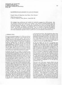
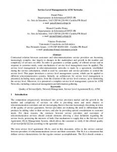
Figure 1: Reference con guration for resource management { B-TE : Broadband Terminal Equipment ; CEQ : Customer Equipment. Consider a periodic ATM tra�c source emitting cells with peak emission period T . Let a given reference point be located along the ATM connection such as the TB reference point, an inter-network node interface (inter-network NNI) or the receiving SB interface (see Figure 1). Cells progressing along the ATM connection experience random delays. Thus, before arriving at the reference point, cell #n has a total sojourn time in the system (Customer Equipment, multiplexing stages, network, etc.) of D + Wn . D is just a time shift (propagation time, processing time, etc.) and can therefore be ignored in the following. Wn is a non-negative random delay component (see Figure 2). The process fWn gn�0 is assumed to be stationary and ergodic. tn is the arrival time of cell #n at the reference point. Because of CDV, measuring the interval between two consecutive cells is not su�cient for estimating the actual peak cell rate of the source. This greatly complicates the task of the peak cell rate control function located in the Usage/Network Parameter Control (UPC/NPC). Indeed, a very basic requirement for this function is that it be transparent to committed tra�c. 2
% $
Network B
B
2.2 Clumping
$
%
. . T .. .�. . . . . .. . . 0.W . 1. �. 0.-.. ? . ? t0
?
n-1
? ?
?
n W .n+1 �. n.-.. ? . tn
?
?
?
Arrivals Reference Point
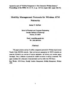
Figure 2: Periodic cell stream passing through a jittering element. Therefore, it must allow for Cell Delay Variation, especially for the clumping e�ect, because even if the source is \well-behaved", the peak cell rate of a connection can momentarily be larger than the declared peak cell rate. The impact of CDV on UPC/NPC mechanisms has already been addressed in previous studies, e.g., [Gui 92a]. Let us examine the case of a Leaky Bucket performing peak cell rate control. Let Wmin and Wmax denote the 10,10 quantiles of the random delay experienced by an arbitrary cell when the source is\well-behaved", de ned by and let
PrfWn � Wmaxg � PrfWn � Wming � 10,10;
(1)
� = Wmax , Wmin:
(2) For a Leaky Bucket [Rat 90], transparency to committed tra�c consists of achieving a very low Cell Loss Rate (CLR), say, 10,10. In this context, it is shown in [Nie 90] that an upper bound for the number N of credits required in the Leaky Bucket is
� � N = T� + 2 where [x] denotes the integer part of real x. It follows that large values of � imply large
numbers of credits in the Leaky Bucket. This results in latency in the mechanism's reaction because it must observe N cells before taking any policing action [Gui 92a]. This is the fundamental drawback of the Leaky Bucket policing scheme.
2.3 Dispersion
The AAL in an end user terminal may be sensitive to dispersion if it has to restore the initial periodic structure of a cell stream. More precisely, the rst arriving cell must be bu�ered for a certain time before the cell disassembling process begins, in order to avoid starvation in the cell disassembler. In fact, starvation must occur with a very low probability, say, 10,10. In [Boy 87], it is shown that this bu�ering delay must be equal to � de ned by (2). Dispersion is not a serious problem for peak cell rate control, because cells arrive at a peak cell rate less than the nominal peak cell rate. It is in fact deeply related to the end-to-end delay constraints of an ATM connection, which point is out of scope of this paper. We shall focus on clumping in the following. 3
3 Cell Spacing A solution for limiting clumping is to space out cells arriving too close together according to the peak emission period. This solution is referred to as Cell Spacing [Boy 90a], which can be performed by the so-called Spacer-Controller [Gui 92a]. This device is a possible hardware implementation of a cell spacer. Other implementations can be found in the literature [Wal 90].
3.1 Spacer-Controller
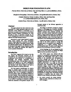
In this section, we recall the basic principles of the Spacer-Controller [Gui 92a] necessary for modeling purposes. The complete hardware description can be found in [Boy 90b]. A unique Spacer-Controller controls all active connections on an ATM multiplex. For this purpose, a cell spacing algorithm is \virtually" allocated to each connection. This allocation is virtual in the sense that a unique cell spacing algorithm is actually hardware implemented. Any time a cell enters the Spacer-Controller, information related to the connection the cell belongs to, is mounted from a memory in the algorithm. Consequently, everything happens as if any connection had its own dedicated cell spacing algorithm. A cell spacing algorithm is composed of two elements (see Figure 3):
� a control block which performs a strict enforcement of the peak cell rate value, while
accomodating for CDV. This accomodation is performed through the use of a parameter � whose value is connection speci c. � a spacing block which ensures a minimum spacing between two consecutive cells of a connection. The spacing period is equal to the peak emission period of the connection.
In [Gui 92a], it is conjectured that if � = � with � de ned by (2), then the rejection probability �loss due to the cell spacing algorithm is less than 10,10 . This ensures transparency of the cell spacing algorithm to committed tra�c. A cell spacing algorithm is used for managing a connection reemission schedule as follows. Let t denote the current time. With each cell entering the Spacer-Controller, two time variables, which are managed by the cell spacing algorithm, are associated as follows: � TRT : the cell's Theoretical Reemission Time ( xed point variable). The connection reemission schedule is composed of the TRT sequence : if bu�ered, the cell must be ideally reemitted at time TRT . � ART : cell's Actual Reemission Time (integer variable). If a cell reemission is scheduled at time TRT , ART corresponds to the next available transmission time. ART is an integer variable since cells are transmitted on a slotted medium (the slot duration is exactly equal to one cell transmission time and is taken as time unit). Cell spacing algorithms are supported by an architecture composed of the following elements: � Context Memory : this memory contains information on each active connection. Specifically, the TRT of the last cells accepted by the control block, the peak emission period T , the parameter � and some other information for the internal management of the Spacer-Controller. 4
cell arrival at time t
?
X := TRT + T
?HH � � �H�HX < t H�H� yes HH�� ? no X := t ? � H yes �� HH �HHX > t + ��H� HH�� no � cell discarding ?
cell is bu�ered and reemitted at time ART
- TRT := X
6 Control Block
? 6 Spacing Block
?
Figure 3: Cell spacing algorithm.
� Reemission Memory : cells are bu�ered in this memory in such a way that they are reemitted at the computed ART value. Its bu�ering capability is �0 which must satisfy �0 � sup f� g (3) connections
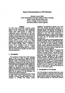
in order to avoid loss due to bu�er limitation. This memory is cyclically explored by a Reemission Pointer which inserts cells on the output multiplex. � Management Block : cell spacing algorithms are implemented in this block which computes TRT s and ART s, and either discards cells or stores them into the Reemission Memory. The Spacer-Controller can be modelled as follows (see Figure 4). Any incoming cell of any connection rst passes through a clock adaptation device. The cell spacing algorithm associated with the connection computes the TRT and the ART and decides whether the cell must be rejected. If not rejected, the cell is bu�ered in the reemission memory at the address corresponding to the ART . The Reemission Memory is read out by the Reemission Pointer.
4 Impact of Cell Spacing on Cell Delay Variation 4.1 Clumping
The most basic function of the Spacer-Controller is to smooth out cell clumps. Speci cally, if cells of a connection arrive too close together, it spaces them out according to the peak 5
Input multiplex
?
Clock Adaptation
?
Spacing Algorithm
Spacer-Controller
? �
Reemission Memory Reemission Pointer
? Output multiplex
Figure 4: Modelling the Spacer-Controller. emission period T by storing and reemitting them. Thus, the time interval between two such consecutive cells should be equal to T . However, since this device is shared between all connections, contention for reemission may occur. Hence, residual clumping may still alter a cell stream after passing through the Spacer-Controller. Roughly speaking, the sequence of TRT s of a given connection is piecewise periodic. Moreover, since storing cells in the Reemission Memory is equivalent to multiplexing connections as in a FIFO queue, the residual clumping e�ect can be roughly approximated by analysing a �ni ? Di =D=1 queueing system [Rob 91]. If we tag a cell stream without infomation on other connections, the clumping e�ect is upper bounded by that in an M + D=D=1 queue (solved in [Rob 92]) where the input process D is the tagged cell stream and the Poisson process M approximates the superposition of all other cell streams ; service times are constant and equal to one cell transmission time. Thus, the clumping e�ect altering a cell stream at the output of the Spacer-Controller is no longer characterized by the quantity � related to the 10,10 quantiles of the random delay Wn , but by the quantity �c related to the random delay wn experienced by an arbitrary cell in an M + D=D=1 queue, namely �c such that (4) Prfwn > �cg � 10,10: Some gures for �c are given in Table 1 for di�erent values of the multiplex load � equal to the load of the M + D=D=1 queue and for di�erent values of the peak emission period T . The limiting value of �c when the contribution of the deterministic input process to the load of the M + D=D=1 queue tends to 0, is that of the 10,10 quantile in the corresponding M=D=1 queue. In fact, the Spacer-Controller can be used for limiting the magnitude of clumping. Therefore, this device can be implemented at the output of a Customer Equipment or of a network (location X in Figure 1) for achieving decoupling of clumping e�ect at network edges (TB 6
T � = 0:8 � = 0:5 � = 0:2
2 24 x x
5 42 13 x
8 46 15 6
10 47 16 7
15 49 16 7
20 50 17 8
50 100 M=D=1 52 53 54 18 18 18 8 9 9
Table 1: 10,10 quantile �c expressed in cell transmission times vs. peak emission period for di�erent multiplex loads. reference points or inter-network NNIs). This solution is referred to as Output Cell Spacing. If a Spacer-Controller is used, the clumping e�ect is characterized by the quantity �c . Figures given in Table 1 could be used as standards on heavy, medium and low load conditions. Moreover, a cell spacing algorithm can be used for checking conformity with respect to clumping. Indeed, from CCITT Recommendation I.371, a user must declare the values of those parameters characterizing CDV which a�ects a cell stream he delivers at an interface. This applies in particular for the clumping e�ect characterized, say, by parameter �c whose values of �c must rely on standards. For this purpose, the o�ered tra�c is analysed through a cell spacing algorithm with tolerance parameter � = �c . Cells are not really spaced out but the cell spacing algorithm is used for managing a connection virtual schedule. If the source is \well-behaved", the ratio of cells detected as non-conforming by the cell spacing algorithm is less than 10,10. Otherwise, it is much higher. Figures given in Table 1 could be used as standards for the values of �c .
4.2 Dispersion Geo
-
V CI1
�� ��?
Geo
�� ��?
Geo
Queue #1
--
D
Geo
Geo
V CIn
-
��LL ��? LLL
Queue #K
D
Geo
--
D
Geo
Geo
Figure 5: Reference con guration. 7
6
LL LL ? ?
�� �� D
Reference Point
SC
The impact of Cell Spacing on dispersion has been studied by simulation in the reference con guration depicted in Figure 5. We consider n periodic connections ; each of them passes through K FIFO queues. V CIi has peak emission period Ti . In each queue, cells experience a perturbation due to a Bernoulli (or Geometric) cell arrival process ; service times are constant and equal to one cell transmission time. Each queue may reasonably represent one multiplexing stage, such as a COPRIN matrix [Boy 87]. A cell experience two types of delay in the Spacer-Controller : the \spacing delay" and the \contention delay". If a cell arrives too close to the previous one, it must be spaced out and is therefore delayed. The di�erence between its arrival time and its TRT is what we call the spacing delay. Now, contention may occur for the reemission of the cell (see Section 4.1). This results in an additional delay we call contention delay. Let Wni , �ni and �ni denote the random delay up to the reference point, the spacing delay and the contention delay experienced by an arbitrary cell of connection #i, respectively. From Section 4.1, �ni satis es Prf�ni > �ci g � 10,10
(5)
where �ci is the 10,10 quantile of the random delay wni experienced by an arbitrary cell in the corresponding M + D=D=1 queue and is de ned by eq. (4). Moreover, it can be shown [Mon 92] that i + � i g � 10,10: PrfWni + �ni + �ni > Wmax c i is the 10,10 quantile of Wni . Besides, it is obvious that where Wmax
(6)
i + � i g � 10,10 : PrfWni + �ni + �ni < Wmin c
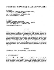
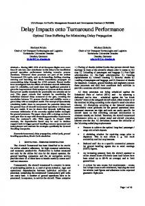
Therefore, a conservative bound for the dispersion e�ect at the output of a Spacer-Controller is �i +�ci for connection #i. Consequently, as � is larger than �ci in most practical cases (especially for large networks), the Spacer-Controller increases the dispersion e�ect only slightly. This increase amounts to �c for each Spacer-Controller crossed. A Spacer-Controller introduces an additional dipersion equivalent to one multiplexing stage. The above results has been checked by simulation for the reference con guration displayed in Figure 5, with n = 7, K = 5, and peak emission periods T1 = 4, T2 = 5, T3 = 5, T4 = 10, T5 = 42, T6 = 4, and T7 = 75. The load of the input multiplex of the Spacer-Controller is � = 80%. Because of simulation limitation, we only handle 10,3 quantiles. Results are given in Table 2. Figure 6 plots the probability density functions of Wn , Wn + �n + �n , and Wmax + wn for peak emission period T = 75. Simulation results are in good agreement with inequality (6) (10,10 must be replaced with 10,3 in this inequality since we deal with 10,3 quantiles).
5 Conclusion In this paper, we have outlined the two basic phenomena of Cell Delay Variation in ATM networks, speci cally clumping and dispersion, and their impact on peak celll rate control and on the AAL of an end user terminal. Clumping can be limited by implementing Cell Spacing which can be performed by the socalled Spacer-Controller. In particular, in view of the agreement within CCITT for decoupling 8
VCI 1 2 3 4 5 6 7
T Wmin Wmax �c
4 5 5 10 42 75 75
6 6 6 6 6 6 6
29 31 31 35 39 40 40
10 11 11 13 14 15 15
�loss
1:63 � 10,4 2:07 � 10,4 1:63 � 10,4 3:00 � 10,4 4:14 � 10,4 4:30 � 10,4 3:80 � 10,4
PrfWn +�n + �n > Wmax + �c g 4 � 10,5 3 � 10,5 3 � 10,6 8 � 10,6 6 � 10,6 1 � 10,5 2 � 10,5
Table 2: Simulation results (10,3 quantiles) { multiplex load � = 80%, number of queues K = 5. the e�ects of CDV at network edges, we have introduced the concept of Output Cell Spacing. However, a Spacer-Controller cannot totally eliminate the clumping e�ect. The residual clumping e�ect can be characterized by using an M + D=D=1 queueing system. Moreover, a Spacer-Controller generally increases the dispersion e�ect only slightly. Note that a cell spacer is not mandatory. There are di�erent ways of limiting the clumping e�ect, for example by under-loading the network or at the TB interface, by using a suitable Generic Flow Control mechanism [Mon 92].
References [Boy 87]
Boyer P., Boyer J., Louvion J.R., and Romoeuf L. : Modelling the ATD transfer technique. Proceedings of the 5th ITC Specialists Seminar, Lake Como, Italy, 1987 [Boy 90a] Boyer P. : A congestion control for the ATM. Proceedings of the 7th ITC Specialists Seminar, Morristown, October 1990. [Boy 90b] Boyer P., Rouaud Y., and Servel M. : M�ethode et syst�eme de lissage et de contr^ole de d�ebit de communications temporelles asynchrones. French patent, INPI no 90/00770. January 1990. [CCITT 91] Draft Recommendation I.371 : Tra�c control and resource management in BISDN. Melbourne 1991. [Gui 92a] Guillemin F., Boyer P., Dupuis A., and Romoeuf L. : Peak rate enforcement in ATM networks. Proceedings of Infocom'92, Florence, May, 1992. [Gui 92b] Guillemin F., Boyer P., and Romoeuf L. : Spacer-Controller : Architecture and rst assessments. Proceedings of the IFIP Workshop on Broadband Communications, Estoril, Portugal, January 1992. [Mon 92] Monin W. and Guillemin F. : Management of Cell Delay Variation in ATM networks. Preprint. [Nie 90] Niestegge G. : The Leaky Bucket policing method in ATM networks. Int. Journal of Digital and Analog Communications Systems, Vol. 3, pp. 187-197, 1990.
9
[Rat 90]
Rathgeb E. : Policing mechanisms for ATM networks, modeling and performance comparison. Proceedings of the 7th ITC Specialists Seminar, Morristown, October 1990. [Rob 92] Roberts J. and Guillemin F. : Jitter in ATM networks and its impact on peak rate enforcement. To appear in Performance Evaluation, Special Issue on Modelling of High Speed Telecommunications Systems. [Rob 91] Roberts J. and Virtamo J. : Superposition of deterministic packet streams in an ATM multiplexer. IEEE Trans. Comm., Vol 39, no 2, February 1991. [Wal 90] Wallmeier E. and Worster T. : A cell spacing and policing device for multiple virtual connections on one ATM pipe. Proceedings of the RACE Workshop on Network Planning and Evolution, London, April 1991.
0.35 0.30 0.25 0.20 0.15
Wn + �n + �n
0.10
n
W
0.05 0.00
-
0
10
20
� Wmax + wn
30 40 Number of Slots
50
60
Figure 6: Probability density functions of Wn , Wn + �n + �n , and Wmax + wn for peak emission period T = 75.
10