Management Systems in Production Engineering
2018, Volume 26, Issue 2, pp 112-118
Date of submission of the article to the Editor: 11/2017 Date of acceptance of the article by the Editor: 02/2018
DOI 10.2478/mspe-2018-0018
IMPROVE THE EFFICIENCY OF THE SERVICE PROCESS AS A RESULT OF THE MUDA IDEOLOGY Augustyn LORENC Cracow University of Technology Krzysztof PRZYŁUSKI Construction Department, Steelcon Abstract: The aim of the paper was to improve service processes carried out by Knorr-Bremse Systemy Kolejowe Polska sp. z o.o. Particularly, emphasise unnecessary movements and physical efforts of employees. The indirect goal was to find a solution in the simplest possible way using the Muda ideology. In order to improve the service process at the beginning was executed the process mapping for the devices to be repaired, ie. brake callipers, electro- hydraulic units and auxiliary release units. The processes were assessed and shown as Pareto-Lorenz analysis. In order to determine the most time consuming process. Based on the obtained results use of a column crane with articulated arm was proposed to facilitate the transfer of heavy components between areas. The final step was to assess the effectiveness of the proposed solution in terms of time saving. From the company perspective results of the analysis are important. The proposed solution not only reduces total service time but also contributes to crew’s work comfort.
Key words: Muda, process mapping, efficiency analysis, unnecessary traffic
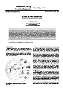
INTRODUCTION In order to increase manufacturing and service efficiency, companies strive to optimise all processes related to their activities. Process optimisation enables achieve better efficiency but also reduces production costs, consumed materials, process time and humans resources [4, 9]. Continuous improvement process is the basis of many ideologies and concepts of production management and human resource management. Majority of these concepts derive from Japanese Toyota Motor Company. One of these concepts is “Muda” what in Japanese means: useless, futile, superfluous. Muda is used for example in Toyota Production System or Lean Management. The first muda concept included seven types of waste which widened to eight in the next years [7, 8]. Waste areas, according to classical muda concept, are shown in Figure 1.
Fig. 1 Seven areas of waste according to the muda concept based on Source: [6].
Individual areas of waste: 1. Overproduction – manufacturing of products, services or information without necessary reported demand, i.e. in advance or in greater quantity than needed. Overcapacity is not consistent with Toyota's key production system – just-in-time. Taiichi Ohno considered overproduction as the most dangerous factor as it leads to the creation of other types of muda (mainly stocks) [6]. 2. Excessive stock – greater than the minimally required quantity of raw materials, semi-finished products, work in progress and finished goods. Presence of stocks is a consequence of overproduction. Excessive stock blocks funds that could be used for other purposes. Also, it increases the risk of accidental destruction, damage, product ageing and generates additional transport and storage costs. The excessive stock may mask problems in business such as product quality, unreliable suppliers and poor technical condition of machines [3]. 3. Errors and quality defects – defective products or improperly performed services are related with necessity of additional inspections, repairs or replacements of faulty product and time devoted to responding to customer complaints. This category of losses includes any work or activity that has to be repeated due to unsatisfactory performance at the first time. 4. Waste of waiting – unnecessary awaiting of the product in the adding value process. Waiting for machines, labour, required materials, tools, instructions or information necessary to carry out the work. In administrative processes it is waiting for decisions, signatures, perUnauthenticated Download Date | 5/24/18 2:48 AM
A. LORENC, K. PRZYŁUSKI - Improve the efficiency of the service process as a result of the Muda ideology mits, certificates, as well as queues (eg in offices and health care facilities) [3, 10]. 5. Waste of overprocessing – any activity that is not necessary to produce a product or service with the parameters and quality required by the customer. Application of advanced and expensive technologies, machines, IT tools etc. In situations where it could be achieved in a simpler and cheaper way with the same result. Signatures, documents, attestations, consent of superiors, which are not necessary to complete the task. This group also includes unnecessary business trips, reports, checks or unnecessary meetings [3]. 6. Waste of transportation – unnecessary relocation of products or materials within the organisation as well as between organisations. Similar to excessive stock, transport generates additional costs and increases the risk of products damage. 7. Waste of motion – any unnecessary physical actions performed by an employee during their work (walking, picking up, bending, moving from place to place) resulting from inadequate organization or improper workstation design [5]. 8. Unused human potential – not using by the organization: ideas, creativity, competencies, talents, and working time of organization’s employees. Performing their tasks below their competences; Discouraging employees and believing that only managers can have good ideas [1]. The article presents the results of the improvement of service processes in Knorr-Bremse. The autors present their method, which include seven steps. In the beginning the Muda ideology was learnt, next for service processes the area of Muda possible to implement was determinated. After that the list of services in Knorr-Bremse service department was identify. The fourth step was listening the units/parts shared in process. Base on this the service process mapping was done. And after that the problem analysis with identification of problem by Pareto-Lorenz analysis and identification of main problems was done. The last step was targeted to finding solution. The methodology of research is presented in Figure 2. To improve service processes in Knorr-Bremse the Muda ideology was used to reduce waste of motion and waiting and transportation. Work at the local Knorr-Bremse service centre includes the following services:
113
1. Warranty repairs – obliges the company to repair the defect of the product or replace the defected product with a new one without any charge. Warranty repair in the Polish service unit of Knorr-Bremse is performed on all equipment for which the competence has been acquired. 2. Emergency repairs – unplanned repairs that aim to restore the value of a damaged object. This type of repair is usually related to inappropriate use of the product or events related to natural disasters. 3. Repair – "overhaul" – is a service of restoring original functionality in a repair devices by replacing or repairing all worn parts. In some cases, ie. brake callipers in project number 7 are done standard repairs and “minor” repairs. Designated as "SO" and "MO" (standard overhaul and minor overhaul respectively). The difference is due to the work done and particularly exchanged parts. It is important to note that both repairs fulfil the condition of restoration of the original functionality of the device. The scope of the repair is a result of the customer’s initiative. Knorr-Bremse manufactures, sells and maintains the electro-hydraulic brake system components. These units include: 1. Brake calliper – provide transmission of braking force from the hydraulic pipes to the friction elements. Hydraulic oil guided to the brake callipers presses on a piston that presses on the brake pads. As a result, the brake pads are pressed to the brake discs generating braking force. 2. Electro-hydraulic unit (EHU) – is a pressure-generating device in an electrical rolling stock. EHU comprises of an electrical pump, oil tank, overflow and proportional valves, pressure sensors and control system depends on the type of EHU. 3. Auxiliary release unit – the additional device in the electro-hydraulic braking system. In the case of passive brakes – clamped in the situation of pressurised oil absence – it is necessary to use the auxiliary release unit so that, in the case of emergency it would be possible to release the brake. Diagram showing the location of individual stations in the hydraulic service is shown in Figure 3.
Fig. 2 The method of research
Unauthenticated Download Date | 5/24/18 2:48 AM
114
Management Systems in Production Engineering 2018, Volume 26, Issue 2
Fig. 3 Current layout of the Local Service Center hydraulic service area
Figure 3 symbols description: 1-2, 19-20: disassembly table, 3-4, 9-10: workshop trolley for parts, 5: manual washing machine, 6: spray washing machine, 7: ultrasonic washing machine, 8: compressed air drying station, 11, 17-18: workshop trolley for parts /repaired devices, 12: EHU assembly table, 13, 21-22: new components to replace, 14, 25: trolley for repaired devices, 15: EHU test bench, 16: locker for test cables, 23-24: brake callipers test machine, 26-27: measuring instruments, 28: hydraulic press. In the diagram (Figure 3), the hydraulic service are divided on "dirty" operations (positions 0 to 10), "clean" (positions 11 to 28) and mixed (positions: 0, 3, 4, 9, 10, 11, 14). 17, 18, 25). To "dirty" operations include following actions - visual inspection and verification of delivered parts and equipment which will be serviced in Local Service
Fig. 4 Block diagram of electro-hydraulic unit (EHU) repair process
Center. Other activities considered as "dirty" are dismantling, washing, cleaning, machining parts. "Clean" operations are related to assembly interfere are undesirable and should be separated in the future of further development of the Local Service Center should be separated. Currently, both zones contain new parts to be exchanged, machined parts for reuse, equipment to analyse, repaired devices ready for transfer to the warehouse. SERVICE PROCESS MAPPING For the analysis purposes, the present state of work performed by the employee is shown on Figure 4 (electrohydraulic unit), Figure 5 (brake calliper) and Figure 6 (auxiliary release unit). Process mapping is a visual representation of a process or a set of processes (operations) with their interrelations. Process mapping is presented in the graphical form using the appropriate graphical symbols [2]. Graphical process interpretations include blocks of process start and process end, its structure and suppliers. The remaining guidelines were omitted due to the nature of the analysis concerning only transport issues between the different stages of the process.
Unauthenticated Download Date | 5/24/18 2:48 AM
A. LORENC, K. PRZYŁUSKI - Improve the efficiency of the service process as a result of the Muda ideology
115
Fig. 5 Block diagram of brake calliper repair process
Fig. 6 Block diagram of auxiliary release unit repair process
In the presented diagrams of the repair of the electrohydraulic unit, brake calliper and auxiliary release unit, standard main repair comprise of the processes like sandblasting and painting are carried out by an external cooperator. In addition, all preparations related to shipment process take place in the same area. After repair process devices are put in one place of storage from they are transferred to the warehouse. Process mapping also shows the execution times of individual operations in the stages. Average operations times during the repair of the hydraulic unit (Figure 7): 1. Preparation of the EHU to disassembly (E1O1) – 15 minutes 2. Main disassembly of the EHU (E1O3) – 45 minutes 3. Components washing with tools preparation (E1O4 wraz z E2O1) – 60 minutes 4. Assembly of the EHU (E3O1) – 225 minutes 5. Tests (E5O1) – 45 minutes 6. Packaging (E5O2) – 15 minutes
Fig. 7 Average repair time of the electro-hydraulic unit
The average operations times during the repair of the hydraulic brake calliper (Figure 8): 1. Technical data register of the brake calliper (E1O1) – 15 minutes 2. Preliminary washing of the brake calliper (E1O2) – 15 minutes Unauthenticated Download Date | 5/24/18 2:48 AM
116
Management Systems in Production Engineering 2018, Volume 26, Issue 2
3. Preliminary disassembly of the brake calliper and force generator (E1O4) – 240 minutes 4. Components washing with preparation of tools (E1O5 wraz z E2O1) – 90 minutes 5. Assembly of the brake calliper (E3O1) – 345 minutes 6. Final assembly phase I (E5O1) – 30 minutes 7. Brake calliper tests (E6O1) – 60 minutes 8. Final assembly phase II (E6O2) – 15 minutes 9. Packaging (E6O3) – 15 minut
Fig. 8 Average repair time of the brake caliper
Average operations time during a single repair of the auxiliary release unit (Figure 9): 1. Preparation of the auxiliary release unit to disassembly (E1O1) – 15 minutes 2. Main disassembly of auxiliary release unit (E1O3) – 45 minut 3. Components washing with preparation of tools (E1O4 wraz z E2O1) – 45 minutes 4. Assembly of the auxiliary release unit (E3O1) – 120 minut 5. The auxiliary release unit tests (E5O1) – 45 minutes 6. Packaging (E5O2) – 15 minutes
Fig. 9 Average repair time of the auxiliary release unit
Operations where time is not given are external operations respectively sanding and painting. These two operations are not counted in Local Service Center process time. Apart from external operations the longest-running operation is the assembly of the device for a variety of reasons. Beginning from technological requirements through complex equipment construction, technical condition of equipment, a flow of materials and tools ending with an experience. In this paper the optimisation of the transport process of the equipment and especially of the brake callipers
is considered because of their weight and size. The device moving occurs in several process areas listed below from the beginning: transfer from the storage area to the disassembly bench or washing table, transfer from the disassembly or wash table to the pallet for co-operation, transfer from co-operation pallet to the disassembly table, transfer between disassembly table and test bench, transfer between test bench and storage place for transfer to warehouse. Transferring is undeserirable operation due to the potential of device damage, employee load, prolonged process time. Pareto-Lorenz diagram is presented in the next subsection and illustrates the transport problem comparing to other inconveniences of the service of rail vehicle braking systems. PROBLEM IDENTIFICATION During the analysis of the service process, the equipment transport method at the hydraulic area was recognised as one of the key operations to be improved. Among the undesirable events determined as problems, the transport activity is in the highest position in Table 1. Table 1 Number of undesirable events Problem
Occurrence
Transportation problem
25
Disassembly problem
9
Part processing problem
9
Painting correction
8
Lack of parts
6
Test problems
1
Assembly problems
0
Employee distraction
0
The trial was carried on 03.01.2017 and concerned 47 devices (38 brake callipers, 3 auxiliary release units, 6 EHUs) on 40 service orders. Devices were classified by weight: large brake callipers > 45 kg, small brake callipers < 45 kg, auxiliary release units < 20 kg, electro-hydraulic units < 45 kg. The transport problem mainly refers to large brake callipers that weight more than 45 kilograms which constitutes 43% of all devices in the trial. Problems with dismantling, part machining (grinding, polishing), painting, lack of parts in the plant (non-standard parts) and problems with the final test and human factor – inadvertence are on the subsequent positions. The factor of inadvertence has an index equal to zero due to historical events that did not occur in the trial from 03.01.2017. The collected data is presented in Figure 10 as Pareto-Lorentz diagrams. Unauthenticated Download Date | 5/24/18 2:48 AM
A. LORENC, K. PRZYŁUSKI - Improve the efficiency of the service process as a result of the Muda ideology Referring to 80-20 rule, 80% of problems are generated by the first three factors, respectively "transport problems", "dismantling problems" and "part machining problems". The solution to the problem of dismantling and parts machining should be considered in the further analysis of the process. In this paper has been proposed a solution for the problem of transport (transporting) of hydraulic devices. SERVICE PROCESS IMPROVEMENT In order to reduce the probability of service interruptions implementation of a column crane with the articulated arm was considered. This solution could improve transport processes between workstations. The column crane with articulated arm would allow to operating throughout the hydraulic area due to the large operating zone of the arm. Before the joint rotation of the arm in the
117
180° range and behind the joint rotation of the arm in the 270°. This could minimise the dead zone around crane’s column. Proposed location of the crane is shown in Figure 11. The column crane equipped with an electric winch would reduce lifting time compared to a manual crane (with hydraulic lift) from 5 minutes and 50 seconds to 3 minutes and 40 seconds. Time measurement was made using a similar existing crane at the air compressors area. The analysis of hydraulic area layout was made with the proposal of a columned crane with an articulated arm. This solution would mainly allow to shorten the transport time of large brake callipers weighing more than 45 kilograms from 5 minutes and 50 seconds to 3 minutes and 40 seconds. It is important to note that the transport problem concerns as much as 43% of all serviced devices.
Fig. 10 Pareto-Lorentz diagram’s for hydraulic service
Fig. 11 Proposed position of the crane column with marked work areas. Marked positions were shown according to the numbering from Figure 3
Unauthenticated Download Date | 5/24/18 2:48 AM
118
Management Systems in Production Engineering 2018, Volume 26, Issue 2
CONCLUSION Implementation of the solution presented in the publication would raise the work quality in several areas in the Local Service Center. It allows shortening the working time by 2 minutes and 10 seconds which in the long term could bring measurable economic benefits to the scale of the growing market of rolling stock repairs in Poland and abroad. Another advantage of the proposed solution is the completion of the Knorr-Bremse Kolejowe Systemy Polska sp. z o.o. corporate values namely "technological excellence" in the principle of perfect process – excellent product, "entrepreneurship" through efficient management of service workers. In the meaning of company image the proposed solution shows customers a high-quality service and technological advancement ie. specialized testing machines or transport equipment. Last but not the least important aspect is the safety and ergonomy of work for employees. Work with a column crane with an articulated arm would make it easier to carry the device in a safe way for the operator and eliminates the dangers caused by the mobile crane such as the movement of the entire mobile crane. In the future it is necessary to further analyse the performance of the workplace along with in-depth analysis of the performance time and delays caused by external factors such as long awaiting for untypical spare parts. The work on this subject is most appropriate because of the rapidly growing rolling stock market and prospects for EU funding for 2014-2020.
REFERENCES [1] J. Bicheno, M. Holweg, The Lean Toolbox. The Essential Guide to Lean Transformation (4th edition), Buckingham, 2009. [2] C. Bozarth, R.B. Handfield, Wprowadzenie do zarządzania operacjami i łańcuchem dostaw – kompletny podręcznik logistyki i zarządzania dostawami, Helion, Gliwice, 2007. [3] A. Grycuk, Lean Government, czyli koncepcja szczupłego zarządzania w administracji publicznej, Anal. BAS. 3 (2011). [4] S. Krawczyk, Logistyka, teoria i praktyka, Difin, Warszawa, 2011. [5] J.-T. Li, H.-J. Liu, Design Optimization of Amazon Robotics, Autom. Control Intell. Syst. 4 (2016) 48–52. [6] T. Ohno, System Produkcyjny Toyoty. Więcej niż produkcja na dużą skalę., ProdPress.com, Wrocław, 2008. [7] T. Osada, The 5S’s. Five Keys to a Total Quality Environment, Asian Productivity Organization, Distributed by Quality Resources, 1991. [8] E. Pawłowski, K. Pawłowski, S. Trzcielski, Metody i narzędzia Lean manufacturing, Wydawnictwo Politechniki Poznańskiej, 2010. [9] A. Rushton, P. Croucher, P. Baker, The handbook of logistics and distribution management. Understanding the supply chain, Kogan Page, London, 2014. [10] P.R. Wurman, R. D’Andrea, M. Mountz, Coordinating Hundreds of Cooperative, Autonomous Vehicles in Warehouses, Woburn, 2007.
dr inż. Augustyn Lorenc Cracow University of Technology, Institute of Rail Vehicle 31-155 Cracow, POLAND e-mail:
[email protected] mgr inż. Krzysztof Przyłuski Construction Department, Steelcon 31-155 Cracow, POLAND e-mail:
[email protected]
Unauthenticated Download Date | 5/24/18 2:48 AM