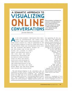
Visualizing Large Structure on Small Screen ... There has been a number of innovative interface tech- .... shown in detail, in Figure 4 vertex labeled (7,7) can.
Manipulating Screen Space with StretchTools: Visualizing Large Structure on Small Screen Mano jit Sarkar and Steven P. Reiss
Department of Computer Science Brown University Providence, Rhode Island 02912 CS-92-42
September 1992
Manipulating Screen Space with StretchTools : Visualizing Large Structure on Small Screen� Manojit Sarkar Steven P. Reiss Department of Computer Science Brown University Providence, RI 02912-1910 USA
Abstract
to the objects of current interest, sometimes called the
focus , and maintain a sense of context with the rest of
StretchTools is a set of tools for manipulating the screen space. The user interface uses the metaphor of stretching a rubber sheet. The basic tool in StretchTools is the handle . A handle is an one-dimensional rigid object of a xed orientation, either horizontal or vertical. As a handle is placed on the screen, engaged, and pulled, the screen expands on one side of the handle and contracts on the other side. Graphical objects on the screen transforms accordingly. The other type of basic tool is the clamp . Clamps are used to impose constraints on the movement of handles by joining handles with one another. In this paper, we show how StretchTools can be used to visualize large structures on small screens by selectively enlarging single or multiple regions of the screen at a time. Transformations achieved by StretchTools have a number of properties that alleviate the problem of user-disorientation due to the introduced distortion.
the space.
As early as in 1982, Spence and Apperley developed a technique called the Bifocal Display for visualizing o�ce information [9]. Brie y, in their system the workspace is a set of information items positioned in a horizontal strip. The display is a combination of a detailed view of the strip and two distorted views, where items on either side of the detailed view are squashed horizontally into narrow vertical strips. In a CHI '86 paper, Furnas pioneered the Fisheye Lens [4] which shows the nearby regions of the focus in detail while still showing remote regions in successively less detail. Later at CHI '92, Sarkar and Brown generalized the concept and demonstrated a prototype Fisheye Lens browser for large graphs [8]. Earlier at CHI '91, Mackinlay, Robertson and Card developed a technique called the Perspective Wall which uses 3D interactive animation for visualizing linear information [5]. Perspective Wall has a center panel for Keywords: Information Visualization, Graphical Videtail and two side panels receding into the distance for sualization, Interface Metaphors, Fisheye Views context.
1 Introduction
In this paper, we present a novel technique of directly manipulating the screen space. The user interface uses the metaphor of stretching a rubber sheet. The basic stretching tool is the handle . The graphical structures are laid out on the screen in usual manner. As a handle is placed on the screen, engaged and pulled, the screen expands on one side of the handle, and contracts on the other side. The layout on the screen transforms accordingly. StretchTools allows users to allocate space to di�erent parts of the structure with great precision.
There is not enough space on a typical computer screen to layout a large graphical structure in its full size and detail. Even so large graphical structures occur with increasing frequency in many application areas as the computer's processing units become increasingly more powerful. One of the challenges of human interface design is to overcome this spatial bounds of small, limited resolution screens. There has been a number of innovative interface techniques designed in last few years for visualizing large inStretchTools has been designed and developed using formation bases on small screens. The unifying theme of object-oriented technology. The subsequent sections deall the techniques is the same { allocate adequate space scribe StretchTools using the object-oriented terminology. However readers unfamiliar with object-oriented � Support for this research was provided by NSF grants CCR9111507 and CCR9113226, by ARPA order 8225 and by terminology should also follow the description without ONR grant N00014-91-J-4052 much di�culty. 1
return value
operation Place Remove Engage Disengage Fix UnFix Clamp Unclamp Move position Position displacement Displacement Draw
arguments position
handle handle amount window
Table 1: Messages accepted by handle object return value operation arguments handle HorHandle handle VerHandle Draw window Table 2: Messages accepted by clamp object
2 StretchTools
Figure 1: Initial screen describes its current position. No two handles of the same orientation can be at the same position, and there must be a minimum separation between them. For example, in our prototype system at least a single pixel must separate any two handles of the same orientation. The Displacement attribute speci es the displacement the handle has undergone since it has been engaged to the screen. It is also possible to Fix an handle, xed handles do not move when pulled. In our prototype system, the four handles along the north, east, south and west edge of the screen are made xed when the system is initialized.
StretchTools is a set of tools for direct manipulation of screen space. The user interface uses the metaphor of stretching a rubber sheet. Graphical structures are laid out on the screen in usual manner. For large structures the details are typically too small or too little for good visualization. Users can visualize details by enlarging parts of the layout by stretching the screen. The screen is stretched by rst placing a handle on it, and then engaging and pulling the handle . The layout constantly recomputes and redisplays itself in real-time. Each part of the layout computes its details based on the space Pulling Handles available for itself. Handles can be pulled. Pulling sends a Move message to the handle. Each handle has a maximum allowable range for movement. Vertical handles may only move Handles towards east or west, and horizontal handles may only The basic tool in StretchTools is the handle . Conceptu- move towards north or south. A Move message causes ally, handles are rigid one-dimensional objects of in nite the handle to move by the smaller of the requested and length. A handle can be either vertically or horizontally the allowable amount. For example, a Move message oriented, but it must always maintain its orientation. has no e�ect on a xed handle. Moving one handle may Some handles and a graph layout are shown in Fig- cause many other handles to move, either because they ure 1. The graph has 100 vertices arranged in 10 rows are directly or indirectly clamped to this handle or beand 10 columns. It also has 180 edges. The label shown cause they are engaged to the expanding or contracting inside each vertex is its detail. Vertical handles are part of the screen. represented by vertical lines extending from the north Figures 2 and 3 show of e�ect of pulling on handle edge to the south edge of the screen. Similarly horizon- on the layout and other handles in Figure 1. Handle tal handles are represented by horizontal lines extend- movement algorithms are discussed in Section 6. Since ing from the east edge to the west edge of the screen. a handle maintains its orientation, and extends from Each horizontal handle therefore intersects all the ver- one edge to the other edge of the screen, the handle's tical handles and vice versa. movement uniformly a�ects the entire breadth or length Table 1 shows the set of messages accepted by handle of the screen depending on whether the handle is horobjects. Each handle has a Position attribute which izontal or vertical. This design choice was made to
Figure 2: Vertical stretching
Figure 3: Horizontal stretching
preserve certain desirable properties of the layouts as they transform under manipulation. These properties are discussed in Section 5.
dles. Figure 1 shows the entire screen divided into sixteen regions by ve horizontal and ve vertical handles (recall that the screen has four xed handles along its four edges). Region objects accept the messages shown in Table 3. The rst four messages are self-explanatory. The Map message maps a point on the undistorted screen to a point on the stretched screen. A region can map only those points which lie inside that region. Associated with each region are a horizontal stretch factor , sx and a vertical stretch factor , sy . The horizontal stretch factor is the ratio of the stretched width to the undistorted width of the region. Vertical stretch factor is de ned similarly. Let Wp and Wd denote the current position and the displacement of the region's west handle. Similarly let Sp and Sd denote the position and the displacement of the region's south handle respectively. Any point p(x; y) in the region is mapped to a stretched point p (x ; y ) by scaling operations using the stretch factors as scale factors as shown below: x = Wp + sx (x ? (Wp ? Wd )) y = Sp + sy (y ? (Sp ? Sd )) Regions created by placement of handles form a twodimensional array. This is called the region-mesh . Each time a handle is engaged to the screen, it causes an additional row or column of regions to be inserted into the mesh depending on whether the handle is horizontal or vertical respectively. These are the functions of the InsertRow and InsertCol messages to the regionmesh object shown in Table 4. The Locate message to a region-mesh returns a region containing the point speci ed in the argument. The returned region can be used to map the point to its corresponding stretched point. The layout object described in the next section uses the
Clamps
A vertical handle can be clamped with a horizontal handle and vice versa. Handles are clamped at the point of their intersection. This is the function of the Clamp message. Conceptually clamping can be thought of as driving a nail through the handles. The messages accepted by clamps objects are shown in Table 2.
Using Clamps
Clamps can be used to cordon o� parts of the screen from distortion. Figure 3 shows two clamps on the northmost handle and two more clamps on the westmost handle. Recall these handles are xed as they are on the edge of the screen. The gure also has two new handles. Clamping separates the top-left region of the screen with four vertices labeled (0,0), (0,1), (1,0) and (1,1) from the rest of the layout. No further distortion in any other region can a�ect these four vertices now. This strategy can be used for viewing multiple regions at the same time as demonstrated in Figure 4. In Figure 3 vertices labeled (0,0), (0,1), (1,0) and (1,1) are shown in detail, in Figure 4 vertex labeled (7,7) can also be seen in detail.
3 Screen Handles divide the screen into regions . A region is a contiguous area of the screen surrounded by four han-
0
0
0
0
0
return value handle handle handle handle true/false point
operation arguments NorthHandle EastHandle SouthHandle WestHandle IsInside point Map point
Table 3: Messages accepted by region object return value operation InsertRow InsertCol RemoveRow RemoveCol region Locate
arguments handle handle handle handle point
Table 4: Messages accepted by region-mesh object Figure 4: Using clamps to view multiple regions Locate and the Map messages to compute its stretched
view.
4 Layout Layout objects hold the geometric speci cations for the
graphical structures and compute their own transformations. Layout objects accept the messages shown in Table 5. It reads and writes geometric speci cations from les in response to Open and Save messages respectively. The Transform message causes the layout to compute its stretched view. Each handle movement causes the layout to recompute and redisplay its transformed view. Every part of the layout computes the detail to be displayed based on the screen space available to itself. Detail computation can be arbitrarily complex. For example, it can be as complex as graph abstraction as in [7] or as simple as font size determination. As an example, in our prototype graph browser, a graph layout is speci ed in the following format: begin graph begin vertex
begin edge
end edge
���
end vertex
���
end graph
return value operation Open Save Transform Draw
arguments le le region-mesh window
Table 5: Messages accepted by layout object Vertex attributes consist of shape, position, size and label. The label is an arbitrarily long text string, also called the detail of the vertex. Each vertex may have zero or more edges. An edge has a source vertex, and a destination vertex. It can be either a straight line, or a polyline with intermediate bend points .
5 Transformation
Transformation induced by StretchTools has a close physical analogue in the real world i.e. that of stretching a rubber sheet. This is the most important contribution of StretchTools . Additionally, a transformation must preserve su�cient similarity between the original layout and the transformed layout to minimize viewerdisorientation. In [2] Eades, Lai, Misue and Sugiyama list a number of properties of layouts { properties which should be preserved by transformations in order to preserve the \mental map" of the viewer. They include three properties, orthogonal ordering , topology and clusters . StretchTools is capable of preserving all of these three properties as explained below.
Orthogonal Ordering
Let p and q be any two points on the screen mapped to two points p and q by the transformation. StretchTools has the property that if q is on the north, or north-east, 0
0
Figure 5: Initial layout
Figure 7: Enlarging another cluster In addition, the transformation uniformly scales (although possibly with di�erent horizontal and vertical scaling factors) points within a single region. If the vertical and horizontal stretch factors are equal for a region, the part of the diagram within that region is enlarged but otherwise completely undistorted.
Clusters
Informally, a set of objects form a cluster if they are close to each other. Figure 5 shows ve clusters consisting tiny objects of various shapes. StretchTools allows the viewer to preserve clusters by controlling the placement of handles and by the degree of stretching. Any cluster of objects can be uniformly enlarged as shown in Figures 6 and 7. Figure 6: Enlarging a cluster or east, or south-east, or south, or south-west, or west, or north-east direction of p, q is also on the north, or north-east, or east, or south-east, or south, or southwest, or west, or north-east direction of p respectively. In other words StretchTools preserves the up, down, left and right ordering of points. 0
6 Implementation StretchTools has been implemented using C++ , X and Motif . Currently it runs on standard SparcStation-1
Topology
and 2 at Brown University and can update the display in real-time for graphs of upto about two hundred vertices and few hundred edges. Two major subtasks in implementing StretchTools are maintaining the connectivity information between handles, and computing the handle movements.
ical sense uses (see [1]). An important consequence is that, the transformation maps the inside of a closed continuous curve to the inside of a closed continuous curve as demonstrated by Figures 5, 6, and 7. Put in another way, if there is no overlap in the original structure, there will be no overlap in the transformed structure.
Using graph theoretic terminology, a handle can be thought of as a vertex, and a clamp as an edge from one vertex to another. A frame is a connected component in this graph. Each time any two handles are clamped together or unclamped, this connectivity information changes.
0
Transformation induced by StretchTools is a homeomorphism because it preserves \open sets" in the topolog-
Handle Connectivity
Each handle is also assigned a mobility number . Con- next immediate west handles using PropagateEast() ceptually, if two horizontal handles have the same mo- and PropagateWest() messages. bility number, when one handle is moved, the other Move (amount) handle must move by the same amount. All xed han- begin dles are assigned a single mobility number since none of if (amount > 0) them can move. Handles belonging to the same frame m = EastMobility(); are assigned the same mobility number. Also all handles s = WestSpacing(); of any two overlapping and mobile frames are assigned else the same mobility number. The algorithm for mobility m = WestMobility(); number assignment is left out due to lack of space. s = EastSpacing();
Handle Movement
The distance a handle is allowed to move in a certain direction is called its mobility . Vertical handles have east mobility and west mobility . Horizontal handles have north mobility and south mobility . When a handle is pulled, the system determines the handle's mobility in the appropriate direction. The outline of the algorithm for determining east mobility of a vertical handle follows:
endif
d = Min (amount, m); if (MobilityNo() = EastHandle().MobilityNo()) m = m; s = s; d = d; 0
0
0
else
�x = EastHandle().Position() ? Position(); m = m ? �x + MinSeparation(); s = s ? �x; if (d > 0) d = d � mm ; 0
0
EastMobility()
else
begin if
0
0
d = d � ss ;
(IsFixed()) return(0);
0
0
endif
else
m = EastHandle():EastMobility(); (MobilityNo() = EastHandle():MobilityNo()) return (m ); 0
if
0
endif
PropagateWest (m; s; d); EastHandle():PropagateEast (m ; s ; d ); 0
0
0
end
else
�x = EastHandle:Position() ? Position(); return (�x + m ? MinSeparation()); 0
endif endif
Below is algorithm for the PropagateEast() method: PropagateEast (mobility, spacing, displacement) begin
(displacement = 0) return;
end
if
Mobility is computed by adding up amount of space available for movement less the space needed for maintaining the minimum separation between the handles. The algorithm is presented as a method of the handle object. The EastHandle() method returns the immediate next handle on the east of the handle under consideration. Essentially the same algorithm is used for determining mobility in other directions. In the expanding part of the screen, the systems is not concerned about maintaining minimum separation between handles. Hence a di�erent quantity called spacing is used instead of mobility for computing handle movements in this part. The algorithm for computing spacing is similar to the algorithm for computing mobility. The algorithm for the Move method of an vertical handle object is shown below. Total mobility and spacing are computed for the handle using the algorithms described above. Amount of displacements are computed and propagated to the next immediate east and
else if
(MobilityNo() = EastHandle().MobilityNo()) m = mobility; s = spacing; d = displacement; 0
0
0
else
�x = EastHandle().Position() ? Position(); m = mobility ? �x + MinSeparation(); s = spacing ? �x; if (displacement > 0) m d = displacement � mobility ; 0
0
0
0
else
s d = displacement � spacing ; 0
0
endif endif
EastHandle().PropagateEast (m , s , d ); 0
endif end
0
0
The PropagateEast() message to a handle moves the posite stretching tools which are constructed from of handle by appropriate amount, computes the mobility, basic handles and has additional power to make the spacing, and displacement for the next east handle, and viewing process more e�cient. then sends a PropagateEast() message to the next immediate east handle. PropagateWest() method has a similar algorithm. [1] Nelson Dunford and Jacob T. Schwartz. Linear Operators. Interscience. 1957. StretchTools has been used to visualize a number of [2] Peter Eades, Wei Lai, Kazuo Misue and Kozo Sugiyama. Preserving the mental map of a diagraphs. Figures 8, 9, 10 and 11 demonstrate an instance. gram. Research Report IIAS-RR-91-16E, InternaThe graph Figure 8 has 134 vertices representing 134 tional Institute for Advanced Study of Social Incities in and around the United States and 338 edges. formation Science , Fujitsu Laboratories Limited, Figure 8 is the initial undistorted view of the graph { August, 1991. in this gure vertices do not have enough space to show their labels. Figure 9 shows the e�ect of expanding the [3] William A. Farrand. Information display in interregion containing St. Louis. Next in Figure 10 Salt active design. Ph.D. Thesis, Department of EngiLake City has been enlarged, now both St. Louis and neering, UCLA, Los Angeles, CA, 1973. Salt Lake City can be seen in detail. Finally a cluster of cities in the northeastern United States is shown in [4] George W. Furnas. Generalized sheye views. Proc. ACM SIGCHI Conf. on Human Factors in Comdetail in Figure 11. puting Systems , pp. 16{23, 1986. Like Fisheye Lens [8] and Perspective Wall [5], StretchTools allows viewers to visualize the entire structure in one window. It smoothly integrates context with [5] Jock D. Mackinlay, George G. Robertson and Stuart K. Card. The perspective wall: Detail and detail. The advantage of StretchTools over other techcontext smoothly integrated. Proc. ACM SIGCHI niques is that it allows the user to precisely control the Conf. on Human Factors in Computing Systems, space allocation. The metaphor of stretching a rubber pp. 173{179, 1991. sheet is very intuitive. Multiple regions can be viewed at the same time in a very natural manner and the rubber [6] Michael Mills, Jonathan Cohen and Yin Yin Wong. sheet geometry naturally preserves orthogonal ordering, A magni er tool for video data. Proc. ACM topology and clusters in layouts. SIGCHI Conf. on Human Factors in Computing The main disadvantage of Fisheye Lens is that it does Systems , pp. 93{98, 1992. not allow viewers to control the space allocation. The Fisheye Lens however provides a very fast and conve- [7] Frances N. Paulisch and Walter F. Tichy. Edge: An extendible directed graph editor. Software { nient way to browse through large information bases. Practice and Experience , vol. 20, no. S1, pp. 63{ Perspective Wall has a very intuitive interface. But, 88, 1990. Perspective Wall is designed to deal with only one dimensional information spaces. Also neither of these techniques have any natural way of viewing multiple [8] Manojit Sarkar and Marc H. Brown. Graphical Fisheye Views of Graphs. Proc. ACM SIGCHI objects at the same time. Conf. on Human Factors in Computing Systems , The techniques such as StretchTools , Fisheye Lens pp. 83{91, 1992. and Perspective Wall manage size of the information bases by mainly distorting the layout. The other ap- [9] Robert Spence and Mark Apperley. Database navproach to managing size is abstraction . In [7] Paulisch igation: An o�ce environment for the professional. and Tichy present two abstraction techniques called Behavior and Information Technology , vol. 1, no. graph abstraction and edge concentration for dealing 1, pp. 43{54, 1982. with large graphs. At CHI '92 Mills, Cohen and Wong described a practical tool for visualizing video data [6]. Their system also takes the approach of hierarchical abstraction for managing size. It may be worthwhile to combine the two approaches. Our experience with the initial prototype StretchTools is encouraging, and we believe that this approach can provide an e�cient and intuitive set of tools for viewing moderately large information bases. We are further investigating the possibility of providing com-
References
7 Evaluation
Figure 8: Initial graph with 134 cities in and around the United States as vertices
Figure 9: A view showing St. Louis in detail
Figure 10: A view showing both St. Louis and Salt Lake City in detail
Figure 11: A view showing a cluster of cities in the northeastern United States