Screen Space Fluid Rendering with Curvature Flow Wladimir J. van der Laan∗ NVIDIA Rijksuniversiteit Groningen
Simon Green† NVIDIA
Miguel Sainz‡ NVIDIA
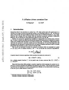
Figure 1: SPH simulations as the one shown here are a powerful tool to simulate fluids, but require advanced techniques to allow realistic renderings of the results. These images show an example of the visual results that can be achieved with our method.
Abstract We present an approach for rendering the surface of particle-based fluids that is simple to implement, has real-time performance with a configurable speed/quality trade-off, and smoothes the surface to prevent the fluid from looking "blobby" or jelly-like. The method is not based on polygonization and as such circumvents the usual grid artifacts of marching cubes. It only renders the surface where it is visible, and has inherent view-dependent level-of-detail. We use Perlin noise to add detail to the surface of the fluid. All the processing, rendering and shading steps are directly implemented on graphics hardware. CR Categories: I.3.7 [Computer Graphics]: Three-Dimensional Graphics and Realism—Virtual reality; I.3.3 [Computer Graphics]: Picture/Image Generation—Display algorithms Keywords: real-time, fluid, rendering, screen-space, noise, foam, curvature flow, GPU, SPH
1
Introduction
For interactive applications such as games, particle based fluid simulation methods like Smoothed Particle Hydrodynamics (SPH) [Desbrun and Gascuel 1996] are commonly preferred to Eulerian fluid representations. This is because the fluid is able to flow everywhere in the scene without the need to define a finite grid, which is costly in terms of memory and computation. Particle methods are also more convenient to integrate into existing physics systems as particles can collide against the scene geometry just like other rigid objects, without the need to voxelize the scene geometry into ∗ e-mail:
[email protected] † e-mail:
[email protected] ‡ e-mail:
[email protected]
the grid (see Figure 1). The drawback is that it is more difficult to extract a surface for rendering. Although there are extensive contributions in the literature [Clavet et al. 2005; Bridson 2008; Liu and Liu 2003] on particle-based fluid simulations, there is very little on rendering particle fluids. Of the methods that have been developed, most are not suitable for real-time use in games. Usually, the fluid surface is constructed in world-space, either directly as a mesh [Stora et al. 1999], or as implicit surface and then polygonized using Marching Cubes [Lorensen and Cline 1987] or a similar method [Rosenberg and Birdwell 2008; Williams 2008]. After this, relaxation and optimization operations can be applied to the entire mesh to increase the smoothness of the surface, which is both computation and memory intensive. Implicit surface polygonization methods also suffer from grid discretization artifacts in frame-to-frame coherence [Adams et al. 2006], as the grid is static and does not move with the fluid. This is especially visible when using low resolution grids in real-time rendering. In [Zhang et al. 2008] an interesting point-based rendering approach is presented where ray-metaball intersections are computed entirely on the GPU in a two pass rendering approach. This method removes the requirements for a grid discretization. If the fluid is moving and rendering is only desired from only one, or at most a few viewpoints per frame, a more memory and compute efficient method is to only construct the surface represented by the particles that are visible to the camera in view-space as in [Müller et al. 2007]. The main contribution of this paper is a splatting-based fluid rendering method that • Achieves real-time performance, with a configurable speed versus quality trade-off. • Does all the processing, rendering and shading steps directly on the graphics hardware. • smoothes the surface to prevent the fluid from looking blobby or jelly-like. • Is not based on polygonization, and thus does not suffer from the associated tesellation artifacts. • Is simple to implement, consisting of a few passes using fragment shaders and intermediate render targets.
• Has inherent view-dependent level-of-detail, since the method is based on a grid on screen-space. Another contribution is a way to generate noise that moves with the particles on the surface of the fluid, which can be used to add foamlike effects and surface detail on a smaller scale than the particles themselves. (a)
2
(b)
(c)
Related work
Rosenberg and Birdwell [Rosenberg and Birdwell 2008] optimized Marching Cubes specifically in the context of particle isosurface extraction, achieving real-time performance for up to 3000 particles. Although relatively fast, the results look quite blobby, and as their method directly renders the resulting mesh there is no way to post-process the result to improve quality. Also, for SPH fluids we typically need at least 10000 particles for the simulation to look realistic. Williams, outlines in his thesis [Williams 2008] a new approach to surfacing particle-based fluid simulations. A generalization of Marching Cubes, called Marching Tiles, is used which allows constraints to be put on the quality and smoothness of the mesh. This results in nice smooth surfaces, but the approach is designed for offline rendering and is not real-time. It also suffers from the same drawbacks as Marching Cubes, such as having a fixed grid. Somewhat related to our method is the projected grid as was introduced in [Johanson 2004] which transforms a displaced surface so that it resembles a uniform grid in post-perspective space as closely as possible. This provides spatial scalability as well as high relative resolution without resorting to LOD schemes. Our method relies on a uniform (per-pixel) grid in post-perspective space as well.
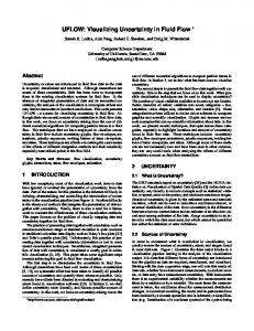
Figure 2: Drawing the particles as spheres (a) front view (b) in view-space and (c) after perspective projection.
dering technique but lacks the advanced smoothing and thicknessbased rendering of our method.
3
In this work we will assume a SPH particle simulation has already been carried out. The input data consists of the positions xi of particles pi , i ∈ {0..n}, in any order. Optionally, the particles can have an associated density ρi and velocity vi coming from the simulation. A high level overview of the method is as follows: Starting from the fluid particle positions, surface depth (explained in section 3.1) and thickness (section 3.3) is written to two render targets. The surface depth is then smoothed (section 3.2), and a dynamic noise texture is generated on the surface of the fluid (section 3.4). Then, a compositing pass is performed that combines the smoothed surface depth, the noise texture and an image of the scene behind the fluid into the final rendering of the fluid (section 3.5).
3.1 In [Müller et al. 2007] the authors present an approach for generating the boundary of a three-dimensional point cloud as a mesh in screen-space, generating the surface only where it is visible. It first computes the depth to the surface at each pixel on the screen, smoothes this depth map using a binomial filter, then polygonizes the depth buffer. The polygonization step is computationally very intensive, and does not map to graphics hardware in a straightforward way. In our method, instead of generating an intermediate mesh, the depth buffer is used for rendering directly. Finally, in [Zhang et al. 2008] the authors present an implicit raymetaball algorithm that does not require an explicit metaball reconstruction, using point based rendering techniques and assimilating the metaballs as point based splats. First, non overlapping fluid surface points are determined using a GPU based dynamic grouping algorithm [Zhang and Pajarola 2007] and an initial ray-metaball intersection is computed. In a second pass the final intersection with the isosurface is determined for each pixel from the contributions of disjoint sets. The advantage of this method is that it does not require a subdivision grid for the surface reconstruction. In order to minimize the bumpy appearance resulting from the simulations, a fairly big metaball radius has to be used, at the cost of very thick surfaces. Level-sets [Malladi and Sethian 1995] have been used extensively in fluid simulations to track the interface between fluid and air as they provide a deformable surface representation that allows for topology changes. We have incorporated a few ideas from levelsets but have not applied the full method, as even efficient level-set methods involve too much computation to be used for this purpose in real-time. Subsequent to our research we became aware of another publication [Cords and Staadt 2008] that uses a similar image-space fluid ren-
Method
Surface depth
Before anything can be rendered the front-most surface of the fluid from the viewpoint of the camera is determined. We do this by rendering the particles as spheres, and retaining the closest value at each pixel using the hardware depth test (see Figure 2). In order to obtain a representation of the surface of the fluid from the viewer’s point of view, we render the particles as spheres using point sprites (screen oriented quads) with depth replacement in the fragment shader. This avoids the use of complex geometry and is a well known technique. Unlike in surface splatting [Botsch et al. 2005; Adams et al. 2006], we do not explicitly splat the normal or shaded color values, but calculate the normals from the depth values while rendering. The reason for this is that the depth values will be manipulated by the smoothing step which will be discussed in next section. In some cases it is desirable to exclude stray particles from rendering as these do not form part of any surface. This is easily accomplished by putting a threshold on the density ρi obtained from the simulation. To make the transition more smooth, the low-density particles can be rendered separately as spray.
3.2
Smoothing methods
It is not desirable for the particles to be visible as spheres since this results in an unrealistic jelly-like appearance. We would like a smooth, flat surface that approximates the particle positions. In our method, we achieve this by smoothing the surface in screen-space. An obvious approach is use a Gaussian blur or variants such as Bilateral Gaussian filters [Aurich and Weule 1995] or more advanced filters like [Chen et al. 2007]. However, straightforward Gaussian blurs will cause blurring over silhouette edges and can cause plateaus of equal depth when using large kernels. Bilateral
filters preserve edges, but are non-separable and therefore expensive. It is difficult to implement a blur with a variable-width kernel efficiently on graphics hardware. As an alternative to Gaussian smoothing, we can look at the problem in a different way: we are interested in a method that smoothes out sudden changes in curvature between the particles, forming a smooth and continuous surface. One way to think of this is to minimize the curvature. This also has a natural motivation, as it is similar to surface tension in fluids which is responsible for the formation of water drops and puddles. A more general name for this process is called curvature flow [Malladi and Sethian 1995]. Curvature flow evolves a surface along its normal direction with the speed depending on the magnitude and sign of the mean curvature of the surface, and is well-known from the level-set literature. In our application we are working on a depth buffer, which means that the surface can only be moved in the z direction perpendicular to the view plane. However, as the viewpoint is constant we still achieve the desired effect of smoothing the surface by moving the z value in proportion to the curvature, thus we define ∂z = H, ∂t
(1)
in which t is a smoothing time step, and H is the mean curvature. From now on, we will call this method screen-space curvature flow. Mean curvature is defined as the divergence of the unit normal of a surface, 2H = ∇ · n ˆ (2) By inverting the projection transformation, a value in the depth buffer is mapped back to a point P in view space Vx and Vy are the dimensions of the viewport, Fx and Fy is the focal length in the x and y direction subsequently, 0 2x 1 −1.0 0 1 Vx Wx F B 2y x C −1.0 C z(x, y) = @ W P(x, y) = B (3) y A z(x, y) @ Vy A Fy 1 1 The normal is calculated by taking the cross product between the derivatives of P in the x and y direction,
as z is a function of x, and y and thus does not change when these are kept constant. We get
∂z
∂x 1
in which Cx = Vx2Fx , Cy = Vy2Fy , we chose to ignore the terms of the derivative of P that depend on the view position Wx , Wy because it simplifies the computations a lot, and the difference is negligible as the contributions are small. The unit normal n(x,y) |n(x,y)|
=
,
(4)
in which D = Cy2
„
∂z ∂x
«2
+ Cx2
„
∂z ∂y
«2
+ Cx2 Cy2 z 2
(7)
Ey =
1 ∂z ∂D ∂2z D − 2 ∂y ∂y ∂y 2
(8)
A simple Euler integration of Eq. 1 in time is used to modify the z values in each iteration. The spatial derivatives of z are computed using finite differencing. The surface may be discontinuous because of silhouettes in screenspace. To prevent blending different patches of surface together it is important to make sure that boundary conditions are enforced where large changes in depth occur between one pixel and the next. At these boundaries, and the edges of the screen, we force the spatial derivatives to be 0 to prevent any smoothing from taking place. The number of iterations is chosen depending on the smoothness that is desired. The more iterations the smoother the surface will be, but this comes at the expense of increased computation time.
3.3
Thickness
One expects an object to become less visible depending on the amount of fluid that is in front of it. To accomplish this we need to compute the amount of fluid between the camera and the nearest opaque object for each pixel, which we refer to as the “thickness“. When rendering, the thickness is used to attenuate the color and transparency of the fluid. The particles are regarded as spheres of fluid with a fixed size in world space. The rendering process is the same as that in Section 3.1, with the difference that the fragment shader outputs the thickness of the particle at that position instead of a depth value. Additive blending is used so that the amount of fluid is accumulated at each position on the screen. Depth test is enabled, so that only particles in front of the scene geometry are rendered, n X
d(
x − xi y − yi , ), σi σi
(9)
where d is the depth kernel function, xi and yi are the projected position of the particle, x and y are screen coordinates, and σi is the projected size.
1 ∂z 0 −Cy ∂x Cx z ∂z ≈ @ 0 A × @ Cy z A = @ −Cx ∂y A z, ∂z ∂z Cx Cy z ∂y ∂x
n ˆ (x, y) =
1 ∂z ∂D ∂2z D, − 2 ∂x ∂x ∂x2
i=0
0
“ ” ∂z ,−C ∂z ,C C z T −Cy ∂x x ∂y x y √ D
Ex =
T (x, y) =
∂z ∂y
1
0
(6)
in which
× ∂P n(x, y) = ∂P ∂x ∂y 1 0 1 0 ∂z ∂z Wx ∂y Cx z + Wx ∂x ∂z C ∂z A×B =@ Wy ∂x @ Cy z + Wy ∂y A 0
∂n ˆy Cy Ex + Cx Ey ∂n ˆx + = 3 ∂x ∂y D2
2H =
(5)
is substituted in the equation for mean curvature (Eq. 2), so that H can be derived. The z component of the divergence is always zero,
Strictly speaking this measure of thickness is only correct if the particles do not overlap, but this is a reasonable assumption in SPH due to repulsive inter-particle forces.
3.4
Noise
Although our method helps to hide the particle-based nature of the fluid the result can still look artificially smooth. Surface detail and foam is an important visual element in real fluids. A straightforward way to improve this would be to perturb the surface using a noise texture and thus add small-scale detail, as in [Johanson 2004]. However, generating fixed noise in world space or eye space makes it appear as if the noise is stuck in place. The challenge is to have noise that is advected by the fluid, but is of a smaller scale and higher frequency than the simulated, particle based fluid.
Instead we propose to use Perlin noise [Perlin 1985] by assigning one octave of noise to each projected particle based on its index value, so that a certain pattern of noise remains with each particle. By using additive blending, this results in a Perlin noise texture in which the octaves move relative to each other and along with the flow. For each particle a point sprite is rendered with a Gaussian kernel. The resulting value is multiplied with an exponential fall-off based on the depth below the surface, so that particles contribute less as they submerge, 2
I(x, y) = noise(x, y) ∗ e−x
−y 2 −(pz (x,y)−d(x,y))2
,
(10)
in which p is the view-space position of this pixel, d the depth as sampled from the surface depth texture, and x and y vary between −1 and 1. The noise texture noise is varied per particle to prevent patterns from becoming apparent.
(a) Without foam
This noise kernel is then summed for every particle on the screen to get a noise value at every pixel to be used for shading, N (x, y) =
n X i=0
I(
x − xi y − yi , ), σi σi
(11)
Fluid should become more perturbed when the flow is violent, and this is achieved by marking the fluid particles when a large change in velocity vi happens, |vi (t) − vi (t − 1)| > τ,
(12)
where τ is a threshold value. For these particles, the noise amplitude will be higher. After a while, the particles cool down and revert to normal.
3.5
Rendering
(b) With foam
In the final step, all the intermediate results are composited into a final image by rendering a full-screen quad. The optical properties of the fluid are based on the Fresnel equation, with a reflection and refraction component and a Phong specular highlight, computing the output color Cout = a(1 − F (n · v)) + bF (n · v) + ks (n · h)α ,
(13)
where F is the Fresnel function, a is the refracted fluid color, b is the reflected scene color, ks and α are constants for the specular highlight, n is the surface normal and h is the half-angle between the camera and the light, and v is the camera vector. Depth test is enabled when rendering the fluid, and the depth returned by the fragment shader is copied from the surface depth (see section 3.1). To shade the surface of the fluid the view-space normals n are calculated using the finite differences of the surface depth d(x, y), as in equation 4. Simply using the finite differences in one direction to calculate the normal will result in artifacts along the silhouettes. When a discontinuity is detected, by comparing the difference in depth to a threshold, we chose the smallest absolute finite difference (for example, the smallest of |z(x, y) − z(x + 1, y)| and |z(x, y) − z(x − 1, y)|). In addition to this, the noise texture N (x, y) is used to perturb the normals to add small, wave-like surface detail to the fluid by adding the partial derivatives of the noise texture to the calculated normals. Furthermore, a grayish color can be added depending on the magnitude of the noise to simulate a surface foam effect like in Figure 3. The thickness T (x, y) is used to attenuate the refracted color of the fluid a, a = lerp(Cfluid , S(x + βnx , y + βny ), e−T (x,y) ),
(14)
Figure 3: Same scene with foam enabled and disabled. Rendered using screen-space curvature flow, with smoothing computed at half resolution.
the thicker the fluid, the more it attenuates the background color. Thin areas of the fluid show through the background scene. When shading the fluid we use a slightly different exponential fall-off for each color channel, so that the color varies in an interesting way with the thickness. For the transparency, the scene without the fluid is first rendered to a background texture S(x, y). The texture coordinates used to sample the background scene texture are perturbed based on the normal of the surface n to give the illusion of refracting the object behind the fluid. β increases linearly with the thickness, β = T (x, y)γ, (15) in which γ is a constant that depends on the kind of fluid, and determines how much the background is refracted. The reflected color b is determined by sampling a cubemap texture of the environment based on the reflected direction, computed from the surface normal and the view vector. 3.5.1
Interpolation
As the PDE for curvature minimization is stiff, and an explicit integration scheme is used, stability issues can arise causing the system to oscillate. For this reason, at high resolutions it takes a lot of iterations at a small timestep to retain stability. A trade-off can be made to sacrifice some quality for performance by using an ap-
(a) Gaussian smoothing
(a) Gaussian smoothing
(b) Screen-space curvature flow
(b) Screen-space curvature flow
(c) With surface noise
(c) Screen-space curvature flow with surface Perlin noise
Figure 4: Comparing Gaussian, screen-space curvature flow and surface noise for close-up view, with the smoothing computed in quarter resolution.
Figure 5: Waterfall, comparing Gaussian and screen-space curvature flow with and without surface noise (smoothing computed in quarter resolution).
proach like that in [Cantlay 2007], doing both the fluid rendering and post-processing steps at a lower resolution. The scaling is difficult due to the presence of silhouettes. Inside a body of fluid, the depth is interpolated linearly, but silhouettes are handled as a special case. These should not look sharp or jagged, if they look blurry or smooth it is more acceptable. For this reason, we blend the fi-
nal shaded color, computed at low resolution, over edges instead of the normal or depth value. This has the effect of smoothing the silhouettes. Interpolation has the result that high frequency features will be lost due to the sampling. Because of the smoothness, half or quarter resolution fluid can look better than full resolution from close up.
(a) Gaussian smoothing
(a) Gaussian smoothing
(b) Screen-space curvature flow
(b) Screen-space curvature flow
Figure 7: comparing Gaussian (a) and screen-space curvature flow (b) on NVIDIA logo (quarter resolution)
the results. Performance figures are shown in Table 1 for both the corridor scene (Figure 6) and the NVIDIA eye logo (Figure 7). In the table, smoothing based on a a two-pass bilateral blur using a Gaussian kernel is compared against various settings of screen-space curvature flow. This method, at quarter resolution is even a little bit faster than the Gaussian smoothing. Half resolution is slower, and full resolution is much slower, because the number of iterations needs to be increased to achieve stability. (c) Screen-space curvature flow with surface Perlin noise
Figure 6: comparing Gaussian and screen-space curvature flow with and without surface noise (smoothing is computed at half instead of quarter resolution).
4
Results and discussion
All benchmarks were performed on a NVIDIA GForce 8800GTS 512 in 1024 × 768 resolution. The result of a NVIDIA PhysX SPH fluid simulation of 64000 particles was rendered using our method. The computation time of the simulation is not included in
It is important to note that the advantage of the presented method is that it allows to achieve a higher degree of smoothness at a lower cost than the Bilateral Gaussian smoothing method, and in particular avoids disruptive artifacts caused by using a separable filter approach on non-separable kernels. In Figure 9 we can see that a similar image quality is achieved by running six iterations of the Bilateral Gaussian, with a performance degradation. In Table 2 we present the overall frame cost for different settings of the Bilateral Gaussian blur filter. It shows that the most significant penalty is paid when the number of iterations is increased to produce a similar image to the curvature flow method, presented in this paper. When adding noise and foam the rendering becomes significantly slower, because of the extra rendering pass that splats the noise kernels. The performance could be improved by rendering only particles close to the surface, if this information is available from the
(a) 0 iterations, image
(b) 0 iterations, curvature
(a) Curvature flow method (c) 40 iterations, image
(d) 40 iterations, curvature
(e) 60 iterations, image
(f) 60 iterations, curvature
Figure 8: The screen-space curvature flow process. Left: rendered images, Right: color-coded curvature. As the number of iterations increases, the curvature decreases. (b) Bilateral Gaussian
simulation. For example, the density ρi might be used, as the density is lower the closer you get to the surface. Figure 3 shows a waterfall with and without foam. The detail added by the foam makes the waterfall look more rough, like a real waterfall, and makes it look less like a synthetic smooth fluid. Figure 4 shows a close-up of the fluid itself, with three rendering methods. With Gaussian smoothing, bumps are clearly visible, with screen-space curvature flow the bumps are smoothed out, but the fluid looks unnatural. By adding surface noise, the surface gets a bit more realism. Figure 5 shows a close-up of the waterfall in the corridor scene, comparing the three rendering methods under somewhat more turbulent conditions. Figure 6 shows a close-up of fluid flowing out of a pipe for both our Curvature Flow method and the Gaussian smoothing approach. Figure 7 shows a comparison of our method and the Gaussian smoothing on another scene simulating a smooth green liquid inside a transparent container. We do not show an image with foam for this case as the fluid is too viscous to form foam. Figure 8 shows the screen-space curvature flow process at work. On the left side it displays the rendered images, and on the right side a color-coded image of the curvature. Black is zero curvature, green is positive curvature and red is negative curvature. As the number of iterations increases, the curvature decreases, which can be seen as the curvature images become darker. The number of iterations can be freely chosen based on the desired smoothness. Only the surface that is nearest to the camera is rendered. In most cases this is acceptable, because the thickness-based shading gives an illusion of volume to the fluid, but it is not entirely correct if there are multiple layers of fluid with air in between them.
Figure 9: Close-up of fluid using curvature flow and the equivalent visual results using 6 iterations of Bilateral Gaussian
Table 1: Performance comparison (in Frames Per Second) of screen-space curvature flow with different settings, to separable bilateral Gaussian blur (Corridor and NVIDIA logo) Corridor dataset Frame (ms) Bilateral Gaussian smoothing Quarter res., 15 iterations Half res., 40 iterations Full res., 100 iterations Foam+noise, quarter res, 15 iterations
18.1 17.5 19.6 50.0 30.0
Logo dataset Bilateral Gaussian smoothing Quarter res., 15 iterations Half res., 40 iterations Full res., 100 iterations
5
22.7 23.3 28.6 50.0
Conclusions and future work
In this paper we have presented a new method for rendering fluids in real-time directly from particle based representations without the need for intermediate triangulation, but which still produces a highquality fluid surface. We have also introduced new ideas to add thickness-based shading and small-scale surface detail to fluids.
Table 2: Performance degradation of the Bilateral Gaussian Method Curvature Flow Bilateral Gaussian Bilateral Gaussian Bilateral Gaussian Bilateral Gaussian
Iterations 1 2 4 6
Frame (ms) 27.8 25.6 31.3 38.5 47.6
Future work may involve looking at using an implicit formulation of the integration scheme, as this would be more stable and require fewer time steps and thus improve performance. This might be difficult as the PDEs for curvature flow are quadratic, not linear. A semi-implicit [Smereka 2003] formulation of the curvature flow could also help. We would also like to investigate using CUDA or DirectX 11 Compute Shaders to improve the performance of the blur stage.
References A DAMS , B., L ENAERTS , T., AND D UTRE , P. 2006. Particle splatting: Interactive rendering of particle-based simulation data. Tech. Rep. CW 453, Department of Computer Science, K.U. Leuven, July. AURICH , V., AND W EULE , J. 1995. Non-linear gaussian filters performing edge preserving diffusion. In DAGM-Symposium, 538–545. B OTSCH , M., H ORNUNG , A., Z WICKER , M., AND KOBBELT, L. 2005. High-quality surface splatting on today’s GPUs. In Proceedings Eurographics/IEEE VGTC Symposium Point-Based Graphics, IEEE Computer Society, Los Alamitos, CA, USA, 17–141. B RIDSON , R. 2008. Fluid Simulation for Computer Graphics. A K Peters. C ANTLAY, I. 2007. High Speed, Off-Screen Particles. In GPU Gems 3, H. Nguyen, Ed., NVIDIA. C HEN , J., PARIS , S., AND D URAND , F. 2007. Real-time edgeaware image processing with the bilateral grid. In SIGGRAPH ’07: ACM SIGGRAPH 2007 papers, ACM, New York, NY, USA, 103. C LAVET, S., B EAUDOIN , P., AND P OULIN , P. 2005. Particlebased viscoelastic fluid simulation. In Symposium on Computer Animation 2005, 219–228. C ORDS , H., AND S TAADT, O. 2008. Instant liquids. In Poster Proceedings of ACM Siggraph/Eurographics Symposium on Computer Animation. D ESBRUN , M., AND G ASCUEL , M.-P. 1996. Smoothed particles : A new paradigm for animating highly deformable bodies. In Computer Animation and Simulation ’96, 61–76. J OHANSON , C. 2004. Real-time water rendering - introducing the projected grid concept. Master’s thesis, Department of Computer Science, Lund University. L IU , G. R., AND L IU , M. B. 2003. Smoothed Particle Hydrodynamics: A Meshfree Particle Method. World Scientific. L ORENSEN , W. E., AND C LINE , H. E. 1987. Marching cubes: A high resolution 3d surface construction algorithm. SIGGRAPH Comput. Graph. 21, 4, 163–169.
M ALLADI , R., AND S ETHIAN , J. A. 1995. Level set methods for curvature flow, image enhancement, and shape recovery in medical images. In In Proc. of Conf. on Visualization and Mathematics, Springer-Verlag, 329–345. M ÜLLER , M., S CHIRM , S., AND D UTHALER , S. 2007. Screen space meshes. In SCA ’07: Proceedings of the 2007 ACM SIGGRAPH/Eurographics symposium on Computer animation, Eurographics Association, Aire-la-Ville, Switzerland, Switzerland, 9–15. P ERLIN , K. 1985. An image synthesizer. SIGGRAPH Comput. Graph. 19, 3, 287–296. ROSENBERG , I. D., AND B IRDWELL , K. 2008. Real-time particle isosurface extraction. In SI3D ’08: Proceedings of the 2008 symposium on Interactive 3D graphics and games, ACM, New York, NY, USA, 35–43. S MEREKA , P. 2003. Semi-implicit level set methods for curvature and surface diffusion motion. J. Sci. Comput. 19, 1-3, 439–456. S TORA , D., AGLIATI , P.-O., C ANI , M.-P., N EYRET, F., AND G ASCUEL , J.-D. 1999. Animating lava flows. In Graphics Interface, 203–210. W ILLIAMS , B. W. 2008. Fluid Surface Reconstruction from Particles. Master’s thesis, The University Of British Columbia. Z HANG , Y., AND PAJAROLA , R. 2007. Deferred blending: Image composition for single-pass point rendering. Computers & Graphics 31, 2, 175–189. Z HANG , Y., S OLENTHALER , B., AND PAJAROLA , R. 2008. Adaptive sampling and rendering of fluids on the gpu. In In Proc. of Symposium on Point-Based Graphics, 137–146.