The actual design proiect is usual'ly preceded by a number of preliminary studies for finding out the ..... many factors, such as the selection of auto-. A.l Product'ional ...... of manual controls does not exceed the capacities of man, processes with ... methods for man, like control room staff and service; do some methods cause.
Valtion teknillinen tutkimuskeskus, Tutkimuksia Statens tekniska forstningscentral, Fonkningsrapporter 23llggl Technicarl Research Centre of Finland, Reseaich li,eports
GUIDELINES FOR: MAN.MACHINE INTERFACE DESIGN
Jukka Ranta Bj6rn Wahlstrdm Electrical Engineering Laboratory
Rolf Westesson Professor Sten Luthander ingenjdrbyrA aktiebolag
Bromma, Sweden
Espoo, August
l98l
(LLIIAB)
rsBN 9sl-38-1279-O
rssN 0358-50?7
Copyrfht @Valtbn teknillinen tu&:imuslceskus (VTT) l98l
Jukabija
- Utgivare - Publisher
Valtion teknillinen tutkimuskeshus (VTT), Vuorimiehentie 5, 02150 Espoo l5 puh. vaihde (90) 4561, teleks 122972 Statens tekniska fonkningscentral (WT), Bergsrnansviigen 5, 02150 Esbo tel. vixel(90) 4551, telex 1229'12
l5
Technical Research Centre of Finland (VTf), Vuorimiehentie 5, SF-02150 Bpoo 15, Finland phone intemat. + 358 0 4561, telex 122972
VTT, Siihkdtekniikan laboratorio, Otakaari
5,
02 150 Espoo 15
puh. vaihde (90) 4561
VTT, Elektrotekniske laboratoriet, Otsvingen 5, 02150 Esbo tel. vixel (90) 4551
VTf,
15
Electrical Engineering Laboratory, Otakaari 5, SF-02150 Espoo 15, Finland phone internat. * 358 0 4561
VTT OFFSETPAINO, ESPOO I9EI
-3ry{,NTA: Jukka, WAHLSTROM, Bjirm & WESTESSON, Rolf, Guidelines for man.machine interface desigrr. Espoo 1981. Valtion teknillinen tutkimuskeskus, Tutkimuksia Statens tekniska forskningscentral, ForJkningsrapporter Technical Resparch Centre of Finland, Research Reports 2311981.105 p. + app.27 p.
|JDC
-
-
331.015.11:658.5
62t.039 Keywords man-machine
syste:ms,
control rooms, nuclear power plants
ABSTRACT
During the past years the level of automation has cons'iclerably increased in modern process plants. One of the consequenses has been the changing role of process operators. The operators have to make decisions on a
qujte abstract level and with abstract conceptions concerning plant economy ' safety, avai I ab'i I'i ty and product qual i ty. Thenefore control room design has become an important factor related to plant safety, economy and
reliability.
The disturbance and accjdent analysis in process p'lants indicate that most of the deficienciiesin existing process control rooms can be avoided by improving the design process itself and by ensuring that the designers
include to an adequate degree all factors which are relevant and essential t0 the man-machine interface (MMIF) system and to the operation of the plant at different design stages. The guidelines are intended to provide support in ensuring that everything essential is included in MMIF desi gn.
App'l'ication design'is a long process involving several persons from various corporate organizat'ion levels. It is also usual that outlines are created at d'ifferent organization levels for delegat'ing tasks and for use by lowerlevels in design'ing concrete activities. From the viewpoint of automation and instrumentation projects, three essentia'lly separate decision-making levels can be discerned, i.e. preparation of outlines and making of decisions at different levels of detail; the levels are also critical node points in MMIF design.
At the top level, Level I, decisjons are made concerning the launching of the project. This leve'l can appropriately be called the top management level. Th'is level creates the general outlines, concepts and criteria for later project pha:;es. The top level arranges studies on such items as productional aims and the suitability of different implementation alternatives, including automation, and uses these to decide on the design project and its implementation
method.
-4Consultants and preliminary Frojects can be used in the studies. This.is the case especially in the areas that seem to become crucial and problematic. Level I has the highest numrber of degrees of freedom, and this is why correct and exact selection of aims and criteria can have a strong
effect on the conditions and'implementation of
MMIF desiqn.
As a decision-making 1evel, Level II mainly corresponds to automation arld instrumentation project management, which makes the decisions
to Level I outlines or to suqgestions from pro.iect members. This level concretizes the Level I outlines as a concrete automation system concept, and ensures that the practical design work proceeds according to the outlines specified. Decis'ions made at this level naturally carry a great importance to MMIF implementation. Typical topics decided at this level include the level of automation, basic MI4IF schedul_ed accordjng
design, cod'ing system,'instrument selection, procedures, etc. Level III corresponds to the design and implementat'ion work carried out by project members according to the Level II and project uanagement dqcisions and guidelines. Tied to schedules, the work involves the pnactical implementation of spec'ified sub-areas, such as control system parameter des'ign, detailed MMIF design,'instrumentation scale design, etc. At this level the number of choices and the degrees of freedom are at a minimum. The designer is forced to follow the technical conditions and Level iI criteria.
structure of guideiines and checklists should correspond to that of tfle decision-making system. This 'is why these guidelines and checklists ane divided into three concretion categories according to the decjsionmqking Ievel for which they are written. The gu'idelines are mainly intended for use as a decision-making aid to ensure that the background factors affecting decis'ion making will be taken into consjderation at a sufficiently early stage, and that the requ'irements of the goals set will also be properly reflected in the decision-making process. Checklists are used at different decision-making phases to ensure that the design has been implemented according to the spec'ified aims and The
outl
i nes .
-5PREFACE
for the design of man-machine interfaces (tilUff ) have been developed as a part of the KRU Project, a Nordic project on the human factors'involved in the design of nuclear p'lant control rooms. The preparation of the grridelines has been supported by the theories and design criteria deve1oped within the KRU Project. These guidef ines
Project has worked in close co-operation with the purdue Workshop on Industrial Computer Systems and with the European Workshop of Industrial Computer Systems TC6. The format of the guidelines relies on earl'ier work done at these two Workshops. The earlier gu'idelines have been adopted and developed according to the design standards and pratices used in the design of large process plants in the Nordic countries. 0n the olher hand, results and viewpo'ints oniginating in the KRU Project have been'included, and this part of the guidelines exceeds the scope of the Purdue Workshop. The planning and design of a process automatlon system, however, is quite similar in all industrial ized countries. It 'is accordingly the authors' bel ief that, subject to minor modification, the guidefines will have a general applicability. The KRU
jn the form of a handbook and can be used as a checklist in ther various phases of MMIF design. This basic structure was chosen because the authors believe that most of the deficienc'ies of existing process control rooms are the result of items "neglected" or "overlooked" at djfferent design stages. Most of the deficiencies The gu'idelines are presented
could therefore be avoided by improving the design process itself, and by ensuring that the designers include to an adequate degree al1 the factors which are relevant and essential to the MMIF system and to the operatingon the plant;. These guidelines are intended to provide support in ensuring that everything essential is included in MMIF design. Technical Research centre of Fr'nrand (vTT) is mainly responsible for the two firstpart of the guidelines (1ever I and II) and the third part (1eve1 III) is created in cooperation with LUTAB (professor Sten Luthander ingenjdrbyrA aktiebo'lag, Bromma, Sweden), where Rolf l,lestensson has been responsible for the final vers'ion of the level III-text.
-6CONTENTS
ABSTRACT
3
PREFACE
5
BACKGROUND AND INTRODUCTORY REMARKS
l.l 1 .2
8
Introduction and background 0n automation design prractices
DTSIGN GUIDELINES
.
LEVEL
I;
COMMON GOALS FOR AUTOMATION
2.1 Introduction 2.2 Phase 1 - preliminary
8
l8
CREATION OF
AND INSTRUI4ENTATION
29 29
analysis and creation of
general goals and criteria A. Questjons relat'ing to aims and goa'ls A.l Productional aims and goals 4.2 Technical requi rements and goa'ls A.3 Goal s relating to product'ion and work organ i zat'ion
B.
I B .2
34
Pl
37
ant si t"ing
Technol ogi
cal
37
s
4t
requ'i rements
C. 0rgan'i zation of preprojects and feasi b'i
'l
i
ty
tud'i es
Phase I I
studies; design
prel imi nary projects and feasi b'i'l i ty recommendations concerning selection and
of
automation system Preliminary projects
A.l 4.2
Production goals and objectives Conditions and constraints Starting of planning and the project 8.1 Planning and organization of planning B .2 0rgan'ization of pl anni ng B.3 Consulting and deliveries
8.4
4l
-
D.1 Level and depth of automation D.2 Design and implementation organization ?.4 Phase IiI - init'iation of automation project A. Checking the recommendations of the pre-project
B.
32
Conditions and constraints relating to B.
D.
32
36
prod uct'ion
?.3
32
Budget and schedules
4? 42 42 4B
49
49 49 52 53 53 54 57
58
7DESIGN GUIDELINES
- LEVEL II:
SYSTEM PLANNING OF AUTOMATION
AND INSTRUMENTATION
3.
I
3.2
58
Introduction Design gui de1 ines
A.
Degree
of
of
60
automation
-
the level and depth
automat'ion
60
B. Principal and structural design of control room C. Choise and design of couding system D. Choice and design of instrumentation E. Physical work environment F. Planning of tasks and task allocation G. Design of procedures and instructions H. Personnel recruitment and training I. Project fo11ow-up and steering DESIGN GUIDELINES
-
LEVEL
III:
- An Mt4lF Design Checklist 4. I Introduction 4.2 Checkl i st deve'lopment 4.3 How to use the checklist 4.4 Eveluation of the checklist A. References and further reading A.l KRUprojectpub'lications 4.2 DesiEn guide'lines, automation projects,
74 77 7B
8l 83 86
88 88
89 90
9l 93 93
criteria, possib'ilities offered by
technological advances, exist'ing
A.3
7?
DETAIL DTSIGN OF AUTOMATION
AND INSTRUMENTATI0N
desiEn
69
MMIFs
ne system model s, human cogn'ition process models, MMIF as working environment
99
Man-machi
103
-8-
I.
BACKGROUND AND INTRODUCTORY REMRKS
I.I
INTRODUCTION AND BACKGROUND
The generdl, evaluations
of
significance of automation rely mainly on technical and economic arguments. It can be noted that, among other things, automat'ion thre
enables a more efficient utilization of the factors of product'ion, impnoves production reljability and use of production capacity, improves product quality and enables the 'introduction of new forms of product'ion and :;ervices, and reduces the rate of env'ironmental pollution per production uni
t.
Factors such as the above have contributed to the major role of automation in the development of production and production innovations. The progress
of
automated systerms has also changed the relatjon between production and man. I'lan is bei ng rel ieved from "perfor ming,' work, as hjs tasks to a constantly increrasing degree involve human mental activ'it'ies. Thjs has also resultecl in the improvement of the physical working environment and in a reduction of tedious, physically, heavy tasks and work in dangerous environments.
also arisen. product'ion control has to cope with 'larger ever ent'ities, sometimes wjth entire production I jnes, at the level of the abstract concept. A result of this is that the decis'ions made by the process operator now have an'increased economic significance. This sets new requirements on the design of man-machine systems and on operator training. New problems have
-9In pract'ice the operat'ion methods and habits of control room personnel affect, in addition to process reliabil.ity and safety, also process operation economy. The operation of the control room personne'l can be affected by the design of the MMIF itself, as well as by training. Process economy and safety will also be'improved if operator convenjence 'is taken into consideration and if the MMIF system is designed to assist the operator in different decision-makjn situations.
level of automation rises, MMIF design has to cope with ever larger entities and w'ith larger quant'ities of information. The rise in automation level also means that automation emerges'in a quite central role in production management. The signifjcance of MMIF design in the overall plant design increases and can be ranked in importance with, for example, process design and plant construction design. Another result of the above is that miscalculations made in automation design, including the determination of the man-machine relation, may have far-reaching and serious conseqdences. This brings forth the need of further development As the
of the aids and methodology used in
MMIF design.
Furthermore, process automation is experiencing a highly dynamic change. Systems based on digital technology are rapidly becoming more and more cOmmon, causing changes in implementatjon principles and jn the control noom environment. At the same time 'it permits new, more versatile techniques, and the MMIF system can be made more flexjble, which gives more degrees of freedom to design and planning.
0n the other hand, the essential change in man-machine interact'ion poses new questions: how is the system to be designed in order to provide support for man's worhing; what new problems are created by distributed systems and by commun'ication through video display units; how are design criteria to be formedn dfld so on?
to form relevant criteria for MMIF design, one has to have some kind of a concept. and a theory on the factorgwhich are involved and how they affect man's behaviour in the control room of a highly automated process. This motivates a theoretical study of man-machine systems and
To be able
-10the creating of models for human, behavior. This overall concept can then be used to form design criteria for assessing different alternatives from man's viewpoint and for directirrg design towards better agreement w'ith the overall aims. The criteria can then be translated 'into concrete design guidelines and checklists which can be used for decision evalua-
tion at d'ifferent project
stages.
Practical design work is in general carried out with the aid of a project organizat'ion. A project involvers "top-down" planning, which proceeds through several decision-making phases from general concepts concern'ing the MMIF system to the detailed design of the various parts of the system. In a way the system js designed several times, but always on a different level of detajl. As a dec'ision-mak'ing process the des"ign work forms a tree structure in v,rhich each design decis'ion corresponds to a branch that in general cannot be returned to as the work progresses. In practice this means that a previously decided, more general concept cannot be changed at a given design level; the concept serves as a
criterion.
A result of t;h'is is that, at each dec'ision-making level, the project should be "foreseen" sufficient'ly far downwards, i.e. a sort of des'ign simulation should be carried out, on the one hand d'or avoiding decisions and concepts that only would mean unnecessary design constraints, and might cause ineffective practical imp'lementation, and on the other hand for provid,ing sufficient and necessary guidelines for continued work and design and for directing the overall system according to the criterja and the aims. design
Another result of the above js that control room design, the practical implementat'ion of the MMIF system, is not restricted to the design of such special control room features as 1ay-out, instnument selection and p'lacing, and so on; all design project levels make decisions which effect and limit the 'implementation of the control room. Decisions concerning,
for
example, the level of automation, the technology to be used (modern distributed system or conventional system) etc. have a very concrete effect on the implementation of the control room. It can be said in general that in the different project phases there are critical decisionmaking stages which, if inadequately, inefficiently or erroneously
-11
-
will result in an inefficient control room design in a later phase. It is therefore 'important to have criteria for controlling the handled'
condjtions
different
of
implemerrting and the aims of the control room design in phases of tfre projectn and for controlling that the various
parts of the MMIF system meet the requirements set on them and that the practical design work progresses according to the general concepts. It can be said that, in prrinciple, a system is as strong as its weakest link, and it is theref'ore important to control that each part of the system meets the requirements set on the whole system.
Criteria which can be generally the operation of
used include variables characterizing the system, such as reliability and safety, economy
maintainability, and variables assoc'iated with human behavior, such as system adaptabif ity', system compatibility with different levels of human functions, unamb,'iguity, etc. Decision-making variables include and
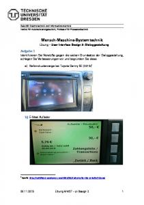
such concrete automation items as 'level of automation, technology to be used, control room design, coding, instrumentation, etc, for which the selection and design decisjons are made'in according to the criteria. The progress of the design and the implementation of the criteria can be contro'l1ed by means of des'ign guidelines and checklists, which are 'intended to ensure that all re'levant jtems and criteria ar e taken into consideration jn nraking design decisions and that the implemented design meets the aims specified at different phases of the project. The diagram below illustrates the relations between the concepts d'iscussed above.
Studies carried out on accidents in the process industry have shown /A16, Al5/ that an acc'ident 'is crucially affected by the combined effect on numerous human factors. Causes can be found both in the control room environment and outside the control room environment - in I4MIF design, control room design, maintenance, operator training, operation procedures, plant organizatjon and management, and operation errors during the event. Many of the above'items and of the deficiencies of "poor" control rooms can usually be traced back to "negligent" design jn 'rhich the special requirements of the man-machine system /415/ have been neglected at different project levels. Some of the problems can be avoided in decision mak'ing and in making design decisions
-12-
IvIAI{.I'IrcH]NE SYST] I\4 TI{EDRY
Verba I ard @nce ptual npdel- s
O:antitative
nodels
HI}IAN FACK)RS
rotl\{Ic
Design
criteria
FACTOR^S
TECH}r)IOGICSL FACTORS
Design
quidelines
PROJETS: - AII'IS - TIIqE CONSTRA INIS - BUDGET ONSN IAINIS - CIII{ER OCDiSTR,i I]NIS
Fig. l.
incorporating
human
factors into a design process
-13by checking that adequate prov'ision has been made for the special requirements of man andl of operation procedures. Assistance is provided for th'is by guidel'ines and checklists. These are, naturally, insufficient for creating an optimum design - the "best design possible" can hardly be found; the purpose is to ensure that al1 important items have been taken into consideration and that a design policy is adopted which is aimed at an acceptable MMIF clearly free of deficiencies.
of the major background factorsin the writing of these guidelines. A sercond goal is to translate to a practical level the theories and design criteria created with'in the joint Nordic project on control room design for nuclear power plants (the KRU Project). The KRU Project, financed in parrt by the Nordic Council of M'insters and in part
The above has been one
from nat'ional sources, has concentrated on the following main themes: control room design, human rel'iabi I ity, and operator train'ing. The following institutions have participated'in the project:
-
RIS0 National LaLboratories, Denmark, have concentrated on manmach'ine system models, operator models and human reljability,
-
the Technjcal Rersearch Centre of Finland (VTT) has concentrated on control and instrumentatjon, operator and man-machine system models, training sjmulators, tra'ining and rel iability analyses, the OECD Halden Reactor Project, Noruay, has concentrated, on process computer systems, control room design and simulators, Studsvjk Energiteknik Ab has concentrated on sjmulators, process stud'ies, and control and 'instrumentation; the engineering offices Ergonomrid and LUTAB, Sweden, supported by the Swedish Nuclear Power Inspectorate (SKI) have consentrated on training and MMIF
-
design analysis. A prerequ"isite for prepraring a set of gu'idelines is the existence of a set of des'ign criteria. The creation of a set of criteria requires that an overall frame (and theory) is available on human behaviour and on the human deduct'ion process, and that a concept of the control room as a working environment is available. t^lithin the KRU Project, the overall picture has mainly been developed by means of theoretical study directed at the creation of man-machine system and operator models.
-14The models have been both conceptual and numerical,
i.e. qualitative
and
quantitative. The models have:;erved as a means of thinking in the generation of different hypothes;es and theories on human behavjor. The hypotheses and theories can be used to form a picture of the various levels and requirements of human behavior, and this can be used as an aid in the selection of design and training criteria /Kl through KIS/.
of theonetical crjteria within the KRU Project has been supported by charting operator tasks jn an actual control room envjronment, and by carry'ing out operation tersts in a simulator /Kl6 through K31/. The development
Job analysis and tests can be used to evaluate the requirements to be set on traint'ng, and on the otherr hand an overall picture can be formed on operator tasks and functions for the evaluation of the hypotheses used in model creation and of the design criteria formed on the basis of
the models. Alongside the theoretical overall picture, an idea has to be available on the technological and engineering possibilities of implementing different design criteria. This viewpoint has been examined in studies 0n modern control rooms employing video display units /K32 through K50/. The studies have examined, firstly, the presentation methods used in displays, comb'inat'ion of colors, display selection and display structural'ization, and, secondly, grounds have been developed for the creati on and des'ign of computer ass'isted operator ai ds , Besi des the evaluation of technological selections and the delopment of technology, design policies and practices as well as practical design criteria have been charted by interv'iew stud'ies and by studying actual design projects.
of the MMIF design project and the MMIF design criteria have also gained an increasing attention in international lihe systematization I
i terature.
The most and systematic work is the "Guidelines" produced by one of the Furdue Workshops (TC6) for use as a checklist at various phases of the
design process, with emphasis on special items associated with MMIF design. At present there are two para11e1 teams within the Purdue
-
International draft versions of the Guidelines /AB, A17/ .
t'lorkshop
Purdue Europe and Purdue
-
which have produced
-15The two set of guidelirnes follow a "top-down" design process 1ogic. The guidel'ines are divided into three major levels. The first, or most general, level is'intended for the top management for use in making the dec'ision on starting an automation project and in specifying the aims to be set on automation in relation to other productional aims. A second, more deta'iled set of gu"idelines is intended for the project management and automation system design level. Fjna11y, a third set of guidel'ines is provided fon deta'i'led MMIF design, in which practical 'implementation'is carried out and details of various parts of the system
are des'igned. The "top-down" thinking of the Purdue Guidel'ines, involving an'iterat'ive adjustrnent of the concept, is basically very sound. The principles of
th'is
approach were
also adopted by the designers of the
KRU
Eu'ideljnes.
of
an automation system as a whole'is also discussed in the tra'ining center of engineers (lNSK0) course materjal /A?5/ and also elsewhere e.g. /A23, A26b/. Each of these references'is a good description of the existing poficies and practices, and brings forth the diverse problems encountered in the implementation of an automation system. Each also contains case studies; the INSK0 materjal The des'ign and implementation
'in particular
in Finland.
is
good
jn this respect, as it reflects the practice in use none of the above three works is actual'ly a set of
Although guide]'ines, they can be seen as design and projectjmplementatjon aids. Furthermore, the two German works place special emphasis on the effects and reflections of microprocessor technology on automation structures, especially on system design and design project organizat'ion.
Concrete MMIF top,ics are discussed in works such as /47, A15, A16, A35, A40, A4l/. Among these, the book by Edwards and Lees /A7/ is somewhat old but stiII contains good basic material. The disadvantage of works
taking the concrete approach to Ml'4IF design - although such works offer good basic material on special topics'in Ml4lF desjgn - is that they rarely d'iscuss MMIF design as part of the design of the ent'ire automation system, or the automation project as a whole start'ing from the spec'ia1 requirements of I'IMIF design. An exception to this are certain EPRI and Sandia Laboratories reports /A29, A30, A32/, wh'ich ana'lyse existing MMiFs and develop methodology by comparing different solution alternatives.
-16-
Besides extensjve works, a good number of articles have been published on automation system design. Sur:h art'icles can be roughly categorized
as fol lows:
; -
general articles and works on project implementation and organization /A2, A1B, Al9, A20, A2l, AZ4, A2B, A36, A3B/, articles on the technical and economic selection criteria used in automation system design /A2, A4, Al0, Al3, AZ1, A3l, 434, 437/, articles on the effects of microprocessor technology on automation system design and project implementation /Al, A4, A5, A33, A34l, artjcles on MMIF design criteria and special topics /A3, A5, 46, Ag, All, Al?, A14, 416, A21, A22, A27, A2g, A36, A3B, A3g/ .
articles by no means form guideljnes, but they do give a idea of how different criteria and far:tors should be emphasized within Such
an automat'ion project. A separate group can be seen in nnore general books and articles on manautomation 'interaction and human behaviour in a l'lMIF environment /81-813/. Although these works do not discuss the concrete design situation and do not give concrete advise for given design problems, they are useful'in forming a p'ici:ure of the prerequisites for human activit'ies. A knowledge of the llatter helps in the selectjon of d'i f ferent techni cal and orgi zati onal al ternat'i ves . As noted in the above, the KRU Project guidelines are intended all the above viewpoints, that i:;:
to
combine
- to bring existing gu'ide'lines to a more concrete level , nearer to today's design policies
- to
and practices, wei ght and combi ne des'ign cri teri a ari si ng from d'if ferent
viewpoints and conditions, jn order to ensure that 'items are jncluded at d'ifferent project phases,
-
tr.i
trinslate
and converr the
all
relevant
theoretical concepts and models
to practical c,esi;n crit.ria.
-17structure of the guidelines has to a large extent been adopted from the Purdue l,lork:shop way of thinking. This genera'l background has been concretized towilrds the practices in use in Finland and in the Scandinavian countries, by dividing decision_making levels into separate internal phases, and by seeking out the decision-making var.iables that have to be "selected and spec'ified" according to the criteria within a project and whose :;election has a concrete effect on the MMIF implementation. As yet, however, the structure of the guidelines is qu.ite general in nature, because the authors have not wished to tie jt to any special cases, and because of general applicability in all branches of the process 'industry. As far as found applicable, the Purdue Workshop materi al has al so beeln uti I 'i zed i n the content of the gu.i de1 j nes . The basjc
As mentioned
in the arbove, every attempt
has been made to maintain general applicability without tying the guidelines to any special cases. This is. why the guidelines conta'in checklist questions which probably wi11 not be
relevant in al1 applications. Because of this, a modular structure has been chosen for the glui de I i nes ; ,'un'importan t,, i tems can be overl ooked without disadvantage to further treatment, 'i.e. the guideljnes can be read in a "jump in - jump out" manner. Items should be bypassed on an intentional and justified basis on'ly; i.e. justif ication should always be found for considering an item unessential. The guidelines are close to a des'ign handbook, but practical experiences and error analyses show that many of the deficiencies of existing MMIFs
result from "small matters"
underestimated or neglected at the design phase. These guidelines are intended to ensure that everything re]evant 'i s 'incl uded duri ng the des i gn work.
-18I,.2
ON AUTOMATION DESIGN PRACTICES
of the purposes of the gujde]ines is to translate the general and theoretical concepts and criteria into practical instructions which can be flexibly used at different philses of a design project. A result of this is that the structure anrl logic of useful guidelines has to follow existing design practice - or has to contain argumented recommendations for al tering the practice, Th'is requ'ires an examination of the design process and an evaluation of the degrees of freedom available to the designer in dec'ision making and select'ions at the diffenent process phases. As the intentiorr is in particular to help achieve a quccessful MMIF solution, the central problem js that of identifying One
the decisjon-mak'ing phases essen'tial and cnucial to MMIF implementation and on the other hand that of evaluating the sensitivity of the lt4l4lF to different design alternatives. This chapter discusses the main Features of the design and imp'lementation of a new production p'lant, inclurling the implementation of the automation and l"lMIF system. The same principal phases will be involved in the expans.ion of an existing plant; the discussion below does not therefore lose its general applicability, although it concentrates on the design of a new plant. It should be noted, however, that the discussion is based on Finnish practice, which may l'imit the genera'l applicability of the conclus'ions drawn. An evaluat'iorr of the references shows, however, that the design practice is in principle similar in all industrjalized countries. "Design and implementation" include here all the activities and work requ'ired for start'ing from spec'i'Fied product'ional a'ims and proceeding to des'ign, implement and start a production p1ant. Thus'it is only the actual productjonal operation of the plant that is excluded from "design and implementation" in this context. Design and imp'lementation are usually carried out project. A project is constra'ined and guided, as
in the form of a
well as by the techn'ical ai ms speci f i ed for i t, al so by schedul e and budget constraints. 0n tbe other hand 'it is true that the time and cost limits set on practical design work make a project perhaps the only efficient form of organizing the jmplementation of extensive design tas ks .
-19proiect approach brrings
its own practical
constraints and requirements. It should be possible to keep track of both the results and the costs of the work. This requires the division of des'ign and implementatjon'into sub tasks so clearly and well defined that it is possible to say where each starts and ends. tieither does this characteristic of project work permit an iterative approach to design and imp]ementation. It.is The
'impossible
to prepare accurate timetables or budgets for an iterative
design process; th'is ur.il I unavoidab'ly introduce an element of inaccuracy into work schedul€S dfld costs monitoring.
In practice an extensive design and implementation work requires that the work of several persons and teams must be co-ordinated and organ'ized. Another practical requirement is that the entire design work should be divided'into logica'l and manageable entities and subtasks which can be unambiguously allocated to a person or a team. This is why the subtasks should also be unambiguously defined, and interdependence between different partial tasks should be kept at a minjmum. 0n the other hand, efficient change of information is necessary within aproject.
div'isjon of tasks'into independent sub-tasks and the allocatjon of tasks to different persons places a special emphas'is on the central decisions made to djrect project work. such decisjons have wide consequences and often deal with r'tems that cannot be foreseen when the decision js made. Furthermore, the decision process is in a sense an irreversible process, as changes to dec'isions once made will also mean a revision or repetition of work already done; this causes delys The
and 'increased
costs. The design process progresses from general concepts
to detailed design, i.e. the designing is carried out many times over byt always at a different level of detail. As a decision-making process, design can be seen as a tree structure which gradually establishes the concrete form of the final solution. The basic problem of such a decision-mak'ing process 'is that it js djfficult to foresee all the
of the decision being made. This places special requ'irements on the programming of the design project. consequences
-20actual design proiect is usual'ly preceded by a number of preliminary studies for finding out the feasibility and economy of the project under consideration. Such stud'ies'include market reports, reports on the need for and ways of capacity expansion, reports on basic productional alternatives, etc. The in'itial impact to starting design may come from any number of causes, for example from a need to expand production capacity or a need to renew and modernjze the production capacity, etc. The
The design
of a new plant can be div'ided into
l.
main phases as follows:
Spec'ifying productional and economic features 2.0ut'lining and phasing of project. 3. Contacting authorities. 4. Planning and carry'ing out construction. 5. Systems planning. 6. Process design and implementation. 7. Electrical and instrumentatjon design. 8. Start-up. The renewal and expans'ion d'ifferent phases but does
to the
of
p1ant.
of an existi ng pl ant may i nvol ve s1 i ghtly not'in itself contain any essential changes
above.
specificat'ion of the productjonal feature of a plant 'involves the Iaying out of the concrete technological and economic aoals to be set for the p1ant. Included are evaluations and assessments of site alternatives, different techn'ical approaches and alternatives, organ'izatory matters, etc. Thjs phase also produces the general automation goals and requirements. Project outlining is concerned with defining work phases, settl'ing work co-ordinat'ion and supervision, etc. Contacts w'ith authorj t'ies can in general be handled within ohter tasks, but in certain cases such as nuclear power plants and certain chem'ical production processes such a large group of tasks is involved that a separate sub-project is required. In any case, this is a work phase which produces safety and reljabjlity reports, as well as automation and 'instrumentation reljab'ility and ava'ilabil'ity requirements. Construction The
-2rplann'ing involves ther work and desiEn on the buildings of the production p1 ant i ncl udi ng p1 arr draw'i ngs , p1 aci ng and si ti ng arch.i tecturar work , ' , and building and cons;truction. Systems planning includes the des.ign of the principles of ther production process, the co-ordination of production l'ines, and the production of basic process technology information. Process des'ign involv'es the detailed design of unit processes. At the two latter phases decisions are.made on design tasks which also
affect the principles of process control and the measureabil'ity of process variables. Electrical and 'instrumentatjon design, as the name implies, is concerned with the design and implementation of electrical systems, automation and instrumentation, as ure]l as the start-up of some of these systems. This is naturally the most important single design phase for I4MIF implementation. A system start-up.includes the formation of the operation organization, training, preparation of operation instructions, runn'ing tests, etc. The start-up is usua'l1y carried out by the same team and organization which will be responsible for the normal operation of the p1ant. Start-up will naturally be supported by the entire project organization as applicable. The table below reprersents an attempt at a summary outline of the main proiect phases from the viewpoint of I'ilMIF des'ign, jncl ud'ing indications
of
how each phase
affr:cts
imp'lementation. The decision-making variables employed inr:lude certain major technologica'l and organizational factors having an essr-'ntial effect on practical MMIF implementat-ion. In the table, the code L means that the project phase jndicated involves decjsions having a large down-to-details effect on the MMIF factor being cons'idene; C means that the decision-making phase produces a concept which controls and guldes subsequent work; D means that the decisionmaking phase does have an effect, wh'ich, however, is not very crucial or decisive. l4l'1lF
As can be seen from thre table, electrical and instrumentation design is clearly the most important and central phase from the viewpoint
of
design. Accordingly, it is appropriate to discuss instrumentation and MMIF design practices in closer detajl. MMIF
-2212345
A. Automation level B. General MMIF design C. D. E. F. G.
7
c
I
C
L
L
ng sys tem sel ecti on and des i gn Instrumentation selection and design Design of tasks and task al1ocation lJorking environment design Procedure and operat'ion insllruction Cod'i
L U
L
D
c D D
des i gn
H. Training and recrujtment [ . Project control and superv'i:;'ion
D
c
Probably the most common way of supplying MMiFs is that the p'lant supplier has the instrumentation work carried out, as applicable, by a sub-contractor accordjng to specifications defined at earl'ier project phases. There are several alternatives for dividing the work, depending mainly on how much design the contractor (owner) himself wishes to carry out, to what extent consultants are used in designing and sub-contracting, and whether one or more MMIF equipment suppliers are to be used. Th'is is a rather difficult problem invo'lving bas'ic principles, for regardless of attempts to employ standard so.lutions as far as possible, autonrat'ion and instrumentation system design and select'ion does not mean a mere cho'ice between
comp'l
eted
sys tems
.
each automation syslfem 'is an individual during the project. Technology advances at a rapid
In a sense,
actually created
rate, and a design project usually takes years, wh'ich in itself means that new des'ign has to carried out at almost all times. This also places spec'ia1 pressure on task allocation, design methods and design tasks.
js
the assumpt'ion that MMIF imp'lementation is awarded to a suitable sub-contractor, and that the buyer of the system participates in preparing specification and'in defining system goa1s. Upon these assumption, I4MIF design and'imp'lementation divides into two parallel sub-projects - the buyer's project and the system supplier's project. These projects can then, at least in principle, be di vided as fol lows: The following discussion
based on
-23-
A.
Buyer's project
l. Definition of system principres, goals and tasks.
2. Project design, schedul.ing, organizatjon. 3. System specification and detailed processing of initial data. 4. Request for ternders, comparison of offers, selection of supplier. 5. Del ivery supenvision. B
.
er' s pro jec.t 1. Preparation of offer. 2. Project design, scheduling and phasing. 3. Detai'lec speci:Fi cations. 4. I4MIF specificarbion, design and implementation. 5. Wiring design and implementation. Supp'l i
6. Installation
and testing.
7. Start-up. 8. Train'ing. 9. Documentation.
.|0.
Maintenance plernn-ing.
The above categorization and
the concrete tasks contained therin depend mainly on the relat'ionrs and d'ivision of work betureen the buyer, the supplier and the consurltants, and should be seen as an illustrative example of an actual work allocat'ion phase. The.inclusion of a consultant would change the above work djvision considerably although the work phases would remain the same.
It
that supplier selection js a crucial decision from the viewpoint of lrlMlF design. The selection of can also be deduced from the above
a given supplier limits the choices to the technology and systems offered by that supp'lier. After this, special approaches and needs can on'ly be taken into consideration to the extent permitted by the selected system during applicatjon design. The table below outlines the importancesof the varjous automation project phases from the viewpoint of MMIF implementation. The factors affecting MMIF des'ign are dsSulll€rC to be the same as for the entjre plant project
in the above.
_24_
AI A2 A3 A4 L A. Automation level L L B. General MMIF design C. Coding system design D L D. Instrumentation selection and des'ign C C E. Design of tasks and task allocation F. Work ing env'i ronment desi gn G. Procedure and operatjon instruction des'ign L D C H. Training and recruitment C I. Project supervision and control
A5
C
C
D
D C
BI 82 83 84 85 86 97 88 89
A. Automation level B. General MMIF design C. Coding system design D. Instrumentation design E. Design of task division F.
BIO
L
C
LL C
DDC
and task al I ocat'ion Working environment des i gn
G.
Procedure and operation
instr.
H. I.
DDD
design
Tra'ining and recru'itment
D
C
Proiect supervi sion and control
DC
As the essence of the practical solut'ion'is often based on the supp'lier's standard solutions, the crucial factor - besjde suppl'ier selection - will be the new design of the standard system. At the new des'ign phase, the des'igners a'lready have available many of the freedoms of choice and degrees of freedom associated wjth MMIF design.
_25_ Hypothetically the buer always has the opportunity to choose the supplier as he wishes, and thr.rs to a certain extent affect ltlMIF desjgn cond'itions. It should be noted, l^rowever, that the items'involved in a man-mach.ine system are only a part of a more extensive set of criteria, on which the selection is baserd. Such other criteria include
-
price, operational goorls and operational alternatives contained wi th i n the sys t;em ,
- system adaptabi i ty and expandabi I i ty, - maintenance, - earlier experiernces from the operation of d'ifferent systems, - suppf ier/customer rea'lt'ions. 1
supplier outlines the system in his offer, which the buyer uses as the basis for supplierr selection accordjng to the above crjteria. The selection is always t;o some extent subject to jnterpretat'ion, as the basic funct'ions of different systems are very much similar; differences between systems are small;'it is difficult to place different factors in the order of importance, and it is often difficult to estimate the actual costs over the entirer ljfe of the system. The
The design
fol I ow'ing
project on a
phases
new automation system
:
l. 0utlining system concept and basics. 2. Project design, scheduling and phasing. 3. Preparation of' system specificat'ions. 4. Detai 1ed speci fi cat'ions
-
hardware'
software
system-user interface
5. Handware configuration. 6. Software development. 7. System setup and testing. 8. Fabrication, includ'ing design. 9. Appl i cation dersign guidel ines.
.l0. Prototype fo1low-up and completion. II
. Documentation.
generally contains the
-26detailed effects on MMIF:'implementation conditions are exerted by phases 3,4 and, partially, g. Also the creation of the concept principles, i.e. phase 1, establishes quite a number of general MMIF impl ementati on al ternat'ives . Phtrses 5 to 7 natural 1y affect the appl .ication p'lan, too, but the boundary conditions and degrees of freedom of these phases are pargely estabf is;hed already dur.ing phases l, 3 and 4. 0n the basis of the above, it can be noted that from the viewpoint of the man-machine system the development stage of the standard system is in many respects as cnucial as thre actual application design. Although the design of the standard system has to d'irect effect on the concrete MMIF implementation, 'it does indirectly create the framework and the boundary cond'itions which cannot be changed or exceeded during appl.ication design. This is why the 6piteria for standard system design should include the creat'ion of an adequate adaptability, so that the requirements of the man-machine system could be taken into consideration during application des'ign. The most
Applicat'ion design is a long process involving several persons from var.ious cqrporate organizat'ion levels. it is also usual that outlines are created at d'ifferent organization levels for delegating tasks and for use by lower in des'igning concrete activitjes. From the viewpoint of automation and instrumentat'ion projects, three essentially separate decision-making levels can be discerned, meaning preparation of outlines and making of decisions at different levels of detail; the levels are also critica1 node
points in
MMIF design.
At the t-op level, Level I, decisions are made concerning the launching of the project. This level can appropriately be called the top management level . This level creates the general ouilines, concepts and criteria for later project phases. The top revel arranges studies on such items as pnoductional aims and the suitability of different implementation a1ternatives, including automat'ion, and uses these to decide on the design project and its implementation me.lhod. Consultants and preliminary projer:ts can be used'in the studies. This is the case especial]y'in the areasthat seem to become crucjal and problema-
tjc.
Level I has the highest number of degrees of freedom, and this is why correct and exact se.lection of aims and criteria can have much effect on the conditions and implementat1on of MMIF design.
a-
As a decision-making level, Level II mainly corresponds to automation and instrumentation project management, which makes decis'ions scheduled
decisions according to Level I outlines or to suggestions from project members- This 'level concretizes the Level I outlines as a concrete automation system concept, and ensures that the practical design work proceeds according
to the outlines specified. Dec'isions made at thjs level naturally carr;, a great importance to MMIF imp'lementation. Typica'l topics dec'ided at this level include level of automat.ion, basic l{MIF design, couding systerm, instrument selection, procedures, etc. Level III corresponds to the design and implementation work carried out by project members according to the Level II and project amangement dec'isions and guidelines. Tied to schedules, the work.involves the practica'l implementation of specified sub-areas, such as control system parameter design, detailed MMIF des'ign, instrumentation scale design, etc. At this level the number of choices and the degrees of freedoni are at a m"inimum. The designeris forced to follow the technical condi tions and Level I I cr.iteria.
structure of guideljnes and checklists should correspond to that of the decision-making system. This is why these guidelines and checklists are divided into three concretion categories accord'ing to the decisjonmaking level for whjch they are written. The guidelines are mainly intended for use as a decision-making aid to ensure that the background factors affecting decision making will be taken into consideration at a sufficiently early stage, and that the requirements of the goals set will also be properly refrected in the decision-making process. Checklists are used at d'ifferent decision-making phases to ensure that the design has been implemented according to the specified aims and The
outl
i nes
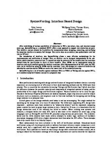
Fig. 2-
.
shows
the relations between design and guidelines.
-28-
Background information:
market
reports , neecl for expans ion,
.-'f e
-1
analys is 1 Prel iminary gand descrj.ption of plant: GuideI ines ______q- arm:;, qoals
I
t- conclitions and requirements orqani zatori- m,ltters iL_
_
_
r -_ I
r---t_. on 'preliminary studies
Guidelines
land criteria for automation : ----Dl l- safety and availability
prodrr.l-{ rri I ',
l- economV and L--
Checklrsts
r--
-----Checking
r--
---1
of rec?nunendations
-t--tDecisj.on on starting
cuidelines
-----t{:
----1
I
''roject: design organization l- consultants
t !891t_..d_".tt.i
yl.. LEVEL II
t-qreation on automation llconcept:
Guidell-nes
- automa t ion r- MMIFs
|
-----tr
I
erre
AIJTOI'IATTON GOALS
econom)', technoLoel', roti"abi-Lit oroanizat-1ons,
L
vrerkinn environrnont
Checkli.sts
IMMIF IMPLEMENTATIO\
Checkl-ists
F'UNCTIONAL DIiSCI] I PT TOII
Checking of concept Commenc j,ng impleme ntat ion
l- control s dlsPlaYs
oF'At"roilt,Trotl
-l I I
----.1: l_ l_ay-out
L
lri :1 :'j':"-"'_
I 11r'LFi.tEI.iTAT1 r\ii CR
I
-_J
ITERT
A
- funct i ona - i.Il'1II. .t-c.
I
I,EVNi, I
Fig.
2
The
different stages of a design process.
T1
-292.
DESIGN GUIDELINES
-
LEVEL
I;
CREATI0N
0F
COMMON G0ALS FOR
AUTOMATION AI{D INSTRUMENTATION
2.1 INTRODUCTION
In outlining the corporate policy, marketing goa1s, €tc. the top management of an enterprise has to make decisjon on the expansion of the existing productiion capacity and on new production areas. such dec'is'ions requi
re the outl ining of an overal
l picture and the
taking of a stand on the production technology emp'loyed; th.is also involves the setting of gener:al aims for automation.
Although the decisionrs concerning automationmainly serve to ougine general concepts' thery may have, through design constraints and criteria, a decisive effect on the degrees of freedom of MI4IF design. This aspect also po'ints out the significance of top management decisions; the management should be able to "foresee" the crucial topics and node points which will arise during the design project. Although the basic concept, once decided on, should be re'iterated as the design work proceeds - if only because of the economjc aspects alone, because the targeted cost/benefit ratio 'is to maintained - unforeseeable problems w'ill always arise in practice. This'is why there is always pressure towards altering the basic concept already decided, 'in particular when relevant items have been neglected or inadequately considered at the
top
management
level.
This should be recongrnized in top management decisjon mak'ing alongside the fact that the automation system is created as the design work proceeds; what is involved'in a project is not a mere rating of fin'ished products. The Level
I
guideline:s are'intended
- to pojnt out thre g6.g that fundamental
decis.ions made
at early
project stages usually have far-reaching consequences, and that they often have a decisive effect on MMIF design conditions,
-30- to i den ti fy and emphas'i ze ii,he deci s j ons and topi cs cruci al to MMI
F
des'i gn ,
- t0 point out the interdependency
between decisions, and how
affects MMIF design conditions, to serve as a checkliston the items and topics
this
dependency
-
whose significance
should be checked and evaluated before commencing the actual design work.
for top management decision making are divided'into three chief phases. The first phase concerns the setting of the general goals of the project. The initial informat'ion 'includes various constraints such as the nature fo the product'ion, envjronmental constraints, social viewpoints and 1ega1 aspects. The result of the first phase'is a genera'l description of the technjcal nature of the p'lant, of productional and economic ajms, and of the goa'ls Set for the des'ign itself, such as
The guidel'ines
scheduling and budget items. The second phase'includes all the further work necessary before the final decision'is made, includirrg preliminary projects and use of
consultants,
if
anY.
is crucial to the whole project.
During this phase' prev'ious experiences and new development features in both design practice and technjcal ghanges have to btl converted into decisions for the guidance of detailed design. Thus, a prel'iminary project "sirnulates" the whole actual des'ign process,, and a'ims at forecast'ing problematic
The second phase
areas. The output from the second phase includes a description of automation poss'ibi I i ti es, a descri pt'ion of desi gn pract'ices and al ternati ves for design implementation, as well as a clearly argumented solution recommen-
design organ'ization, recommended t'imetable and budgeL, and a cost/benefit analysis.
dation, which also describes a
lrecommended
a
the final decision on starting the project' This phase also establishes the automation concept according to the prev.ious phases, sets the automation design criteria, decides on proiect organizati0n and project supervision, and settles t'imetable and budget
The
th'ird
questions.
phase produces
-31 Both guidelines and checklists are used at Level I (cf. Fig. z). Gujdelines are used at all Level I phases to ensure that all relevant factors are taken into consideration and evaluated during the decision
making. Checklists are main'ly used at the third phase to ensure that the prel iminary projects halve prepared the matter to an adequate degree and that all items relevant to project goals have been included. chr:cklists fall 'into four major categori:es, each of which calls attention to d.ifferent deci sion-making cond'itions and The guidelines and vi ewpoi nts
Group A included
topics concerning productional and economic corporate goals as well as the production technol0gy itself. Group ts relates to topics concerning the proposed siting of the plant and the consequent 1egal, social and environmental aspects. Group c involves top management decision-making goals and resul ts, and includes items related to design, des.ign organization,
t'imetables, budget and design criteria. Group D concerns; pre'liminary projects and preliminary activities serving as a decision-making aid.
third group (c) together with the fourth group (D) provides the practjcal means o{'guiding the design work according to the criteria produced by the first two groups (A and B), including the means of superThe
vising the technical content of the project. The topics presented in group c are crucial to the entire project. poor decjsions.in these topics will in general be reflected throughout the project, as the top level establishes fundamental decisions that cannot be changed at later project phases. This points out the importance of project supervision, as practical design will decjde the solution to "sub-problems,, , and the final result will be formed by the sum of such solutions. The project management is responsible for ensuring that the whole meets the goa'ls set.
-32?.2
PHASE
I.
PRELIMINARY ANALYSIS AND CREATION
OF
GENERAL GOALS AND CRITERIA
4.'
-Qse:!tql :_ - rel elil
g_
!g_elu:_el9_ ggcl
:
This group contains viewpoints concern'ing the product'ional and technical character of the plant being des'igned, and the airns and goa'ls to be set to productjon. These items are reflected in MMIF design through many factors, such as the selection of automation level.
A.l
Product'ional a'ims and goals
Products
Specify the nature of the production process, including the product, with particular attention on the fol'lowing:
Is the process a multiproduct
process, or
is a
single product involved? Paral I el produc ti on I i nes , 'if any? What kinds and combinations of sub-processes
will
to be used'? Are changes to be expected in product or product quality, and how often will such changes take place? have
All
the above items set criteria on automat'ion implementation and on the implementation alternative, and will be reflected in MMIF design throullh, for example, different automat.ion
sys tems
Preliminary projects will also require exact answers to the above questions for s;pecifying the automation concept.
-33' Capac'i
ty
and qual i ty
Specify the capacity of the plant and evaluate the consequences to production management, as well as the further consequences to automation design criteria. Specify the estimated fluctuation in plant throuhgput in relatjon to maximum capacity and the consequences to production management. Specify the desired product and production quality; also spec'ify the general princ"iples of qual'ity control Specify the permissible quaf ity margins. What are the consequent requi rements on product'ion management?
All the above items affect the definition of the automat'ion concept and w'il I be reflected in practical l'll4lF implementatlon through, f'or example, the automation level and jnstrumentat'ion chosen.
Plant implementat'ion al ternatives the plant is to be implemented: by expanding an existing plant or by build'ing a new plant; or is it only a mod,ernization of the automation system that is Specify
ho'r'r
i nvol ved?
These 'itern:s
will
selectlon rlf establ i sh
,Ci
be reflected in different ways to the the automation concept, and w'il I therefore
fferent starting
poi
nts for
prel imi nary
projects.
Plant and prodruction
economy
Specify thr-. economic and production goals set for the plant, including the productivity requ'irements on capital, work, energy and raw materials.
-34Specify the targeted and economically necessary plant throughput rates i n rel ation to max'imum capaci ty. uti I i zati on rates. Each
of the above criteria will affect e.g. the selection
of automation level
and techniques
to be emploed, absolutely
essent'ial initial information for preliminary projects, w'ill thus be reflected jn MMIF implementation.
and
Specify any other applicat'ions or sales targets for the system being designed; these w'ill affect the automation concept and system economy.
A.2 Technical r:equirements and goals
General nature
of the pl ant
Spec'ify the sub-processes involved, as well as their connections, with special attention on the requirements expectations on sub-process interaction.
and
Specify the buffer storages, transport and conveyor
facil ities and communications required. are the consequent genera'l requirements and goa'ls data processing and automation criteria?
What
special features wjll be involved in the and servicing of the plant?
What
will
on
ma'intenance
effect on the automation concept, and w'ill be reflected in MMIF design throqh e.g. the automation level chosen.
The above items
have an
-35Nature
of
sub-processes
Specify the technicaJ feature of the sub-processes; i n parti,cul an: Spe,:ify continuous processes and batch processes. Spe,:ify the general stabilf ty characteristics of
the sub-processes. Sper:ify the time constants, with specia'l attention on rapid and exceptionally slow rates of change. Sper:ify the process sensitivity characteristics, with specia'l attention on external disturbances, variations in raw materials, and maintenance. Whaib 5psqi11 consequences and requirements are caused by production plahning and production control? The above items are
highly crucial to the definition of the
automation concept, and w'il I cause direct demands on e.g. the selection of automat'ion level , and wi I I therefore be reflectect in MMIF implementation.
Plant rel iabi f ity and avai I ab'i1i ty Specify the goals and requirements to be set on plant reliability and ava'ilability; check whether safety and reliability aspects require the starting of a separate sub-projerct in co-operation with the authorities - this may be thre case in, for example, nuclear power plants and certa'in plants of the chemical i ndustry. Specify any special goa'ls associated with crucial items, which may be reflected in equipment choices, provision of stand-by systems, personnel recruitment, training, etc.
will
be reflected in MMIF implementatjon through automation level, instrument selectjon, recruitment, etc. The above items
-36A-3 Goals relating to production and work organ'ization
General personne'l
po1
i cy
specify the general grrals and practices concerning corporate management pof icy, personnel pof icy and worker participation. Are the ex'isting polircies and practices suitable for the production process being des'igned, or are any special methods requi red?
uate how the exi s'bi ng pof ici es and pract.ices sui t automation design and project implementation; place special attention on evaluating the need caused by MMIF design for special approaches or special actions. Eval
It is naturally advan:bageous to successful MMIF design that all know-how and expertise on different items available within the enterprise is utilized as fu1ly as possible. Specify and special i't:ems associated with the nature of the plant, such as:
- Is shift work required, or are normal working hours suff i c'ient?
-
What demands are caused by exceptiona'l situations
or
emergencies, vrhat support or background organizations are needed, and vrhat are the prerequ'isistes for plant mai ntenance?
-
Which tasks are made necessary by the nature plant, and which nesult from lega'l aspects?
-
What
sk'ills or
konwledge
of
the
are required by the nature
of the plant?
-
are the consequences concern'ing control and operation personnel?
What
room
Evaluate the consequences of the above items to:.the organizat'ion of the automation system design.
-37Available
manpowen
and personnel
Evaluate the competence of the manpower locally available. Make a rough estimate on wheter internal transfers will be used ih Fr3cFuitment, or whether and to what extent external 'l manpower wi 1 be used.
a general estimate on the consequences of the above to tra'inirng; make rough estimates of the arnount, organization methods and scheduling of the tra'ining required.
Make
a general estimate on the consequences of the approach to further or supplementary training.
Make
chosen
is
the significance of the chosen solutions to the organ'ization of the design work?
What
9, -9qrdi
!igl: -erd-e9[elts i!!:
-ls].e!119-!9 -pfedsgligl
Th'is group of questions is concerned with the necessary constraints and condit'ions resulting in part from the nature of the p1ant, and 'in part from the siting of the plant. These jtems should beincluded as necessities 'in the design. Typical items belonging to this group include 1ega1 requirements, soc'ial customs and habits, environmental factors, etc. They will in general have a large effect on the cond'itions of MMIF design and, consequently, on the practical implementation B.
I
of
MMIF design.
Plant si ting
Geographical attributes
Specify the "physical" necessities resulting rom the plant
site, such as:
-
Quality and security of supply of raw materials.
-38-
Storage and availab'ility of spare parts, including those required by automation and instrumentation. Availabjlity of transported services (such as oil,
-
coal, etc. ).
- Availability of piped services electrici ty)
-
Avai l ab'i I 'i ty
These
.
of
manpower.
are prob'lems wh'ich
inh'ibitive at the chosen in any case give rise to specia'l
may become
site. In general they will of
automation imp'lementation, such as compensation variat'ions 'in raw materials, or emergency procedures.
requi rements
for
(such as water, gas,
I,latural envi ronment
Specify the local climate and the range of estimated meteorologi ca1
cond j
In particular,
check
Each
t'ions
temperature variations in the natural watersava'ilable, humi di ty f'l uctuati ons , spec'ia1 problems caused by high winds' probabi I i ty of earth tremors.
of the above items will affect the technology to be
chosen, e.g. instrument and procedure selection, and, consequently, practical MMIF implementation. 0n the other hand, environmental variations and fluctuations can be compensated by a suitable select'ion of automat'ion level and procedures.
Technological environment Evaluate the effects of the jnfrastructure on production, with attention on items such as the following:
-39-
- Is technical assistance or maintenance avairabre l oca'l 1y?
-
What
is the level of the technological
know-how
available loca11y, what research institutions are I
oc,ated nearby?
-
what transportation abailable?
-
How secure
is
facilities
and
confitions
are
the availability of spare parts?
The abovc' items affect the required support and maintenance organ'i za'bi ons , tra'ini ng, operation procedures, i nternal
division of work. The condit'ions of MMIF implemenrlation wil I thus also be 'indirectly affected.
manning and
Avai I abi I i
ty of
manpower
Evaluate the size
of the local labor pool and the range
of
s
techni
cal
sk i I I
ava'i i abl e.
0n the baLsis of the above, evaluate the need for producing manpower from outside the local area. Also evaluate the need
for trajninq.
Check language problems,
requirements; VDUs
this is
if
any, and any related special important for operation instructions,
and procedures.
Specify loca'l working hours; legislation, habitual working and non-working hours, 1oca1 holiday patterns and annual vacation practice; these will affect work organization, procedures and shift team structures. Evaluate the viewpoints, attitudes and contracts of the local/national labor unions on working conditions, job structur"i,ng, work patterns , etc. as these i tems w j I I affect the job dresign of control room personnel, procedures, etc.
-40Besides organizational measures, the above 'items will affect the selection of automat'ion level, procedures and control room lay-out des'in. Consequently, MMIF implementat'ion wjll
be both
directly and ind'irect'ly affected.
0ther regulatory and legal requirements The operation of power plants and
certain product'ion plants, such as nuclear certain plants of the chemical industry, is governed by regulation jssued by the authorities with the aim of regulating the relation ofthe plant and the envi ronment. These regu'lation are si te speci f i c, arid are reflected in production control, and further in e.g. instrument, automation level and procedure selection. MMIF implementat'ion w'il I thus al so be both di rectly and indi rectly affected.
'is required for the physical protection of the plant and 'its operation, and what are the protection control Determine what
systems.
Determine the requirements concerning
-
chemi
cal
po1 'l uti
on I evel
s,
rad j
at'ion 1 evel s , other pollution levels.
Determine the
- pollution control systems, - requ'ired protection and pollution control systems, - required procedures and ljcence arrangements with the authori t'ies
.
Determined the required procedures in abnormal situations and in case of exceptionally high pollution levels.
-4r8.2 Technological requirements Determine the requ'irements
resulting from standardization
and
from various compatibility aspects. Determine the corporate policy requirements on safety, protection and control; in particular determ'ine the areas where such requirements are to exceed the requirements of offic'ial regulations (cf. B.l - Other regulatory and 'lega1 requirements). 9.-9
tgerizs!ie! -ef..prepreieg!: -erd - fee:i! i li!v-: !!gie:
the complet'ion of rough outlines for the p1ant, and of the pl ant goal s and criteri a , the pno'bl emat'ic areas wi I I be know whi ch require further studying and feasjbility studies before settling the fjnal outlines and before the actual design project is started. Upon
Thi
s
appl i es al so 'bo automat'ion
.
Select and prob'ide clear arguments for the manner of carrying out preliminary projects and feasibility studies. Specify whether j n-house personnel wi'11 be used
'in the form of
prel iminany projects, consultants will be used in feas'ibi 1i ty and other studies, both i n-hrluse personnel and consul tants w'i I I be used.
to the clearly established design goals and aims, and with a full konwledge of the in-house resources and possibil ities.
The decisjon shoul,C be made according
Prepare estimates for preproject costs and t'imetables, and select the preproject personnel so that as wide a range of automation konwledge as possilole is covered; the relevant items are those concern'ing the selrection of automation level; viewpoints concerning appf ications, such as hardware aspects, software and procedure des'ign aspects, and aspects associated wi th work psychology and the workjng environment.
aspects, spec'ial
Ml'4IF
-42that adquate information and reports exist for prelim'inary projects, and that the overall goals set for design are unambiguously specified and understandable; in particular make sure that any special aspects have been pointed out and are known concerning the evaluation Ensure
of 2.3
automation implementation.
PHASE
II -
PRELIMINARY PROJECTS AND FEASIBILITY STUDIES;
RECOMMENDATIONS CONCERNING
SELICTION AND DESIGN
OF
AUTOMATION SYSTEM
9, -?
tel iuinery-prsieg!:
The information needed
for startjng
design work
is
usually
acquired from preprojects and consultants. The manner of carry'ing out preliminary projects is decided at the top management level, but the results of preliminary projects form the basis for final dec'isions made at the top level and for the starting of the actual design project. In many senses, preliminary projects are crucial to a successfully implemented automation.
Preliminary projects should be able to forecast design bottlenecks. A prel imi nary project simul ates the ent'i re desi gn process, and may involve profound studies in problematic areas. A preliminary project covers all essential design aspects, and will thus have to take a stand on e.g. des'ign organization and, for example, on goals to be set for the working environment. Although this discussion focuses on preliminary projects from the viewpoint of automation des'ign, it is natural that preliminary projects have to be launched over the entire range of plant operations. D.
I
Level and depth
of
automation
A prefiminary project creates a proposal on the automation concept and on 'its implementation alternatives. Included are descriptions of automation at the functional level: controls,
-43protections, interlocks, state transjtions, displays, reports, data management, communications, 0tc., for all sub_processes and the entire plant. Furthermor, the ,'depth,, of automation will be described, i.e. which techniques and methods will be useo and where (stabil ization, adaptive control, optimizatior.t, coordination, rsfs). All this will be done with respect to the different operational states of the plant, such as start-up, normal operation, slnut-down, disturbances, emergencies. The functional automatjon dr-.scription can also be made from the operator,s viewpoint; i.e. which operator activities are to be automated (contro1, monitoring, diagnostics, dec.isions, etc). The level of automation'is thus in this context interpreted as a manydimensioned concept,'in which categorizatjon accordjng to operational :;tates forms one dimension of eval uat.ion, categorization by sub-processes form another, and the techniques and methods :lo be used fo'nm a third dimension.
It is also e:;sential that the preliminary project should examine the practicatr implementat'ion alternatives for autornation and the technology available, and evaluates the cost/benefit effects of the propos;a1 .
It is also inrportant that relat'ionsships between automation and process cles'ign are brought
forth with
adequate crarity. l4any of the central control I abi I i ty and measurabi'li ty probl ems can and should be solved by means of appropriate process design, utilizing the desgrees of freedom available for process, equipment and instrumentation design.
Minimum
level of
automation
In this context, the minimum level of automat.ion, i.e "necessary" automation includes everything necessarily required for maintaining safe and reliable plant operat.ion. The requirements on the minimum level of automation arise partly from safety and reliability criteria, and partly from human ljmitat'ions, such as human deficiencies in control'ling processes having exceptionally long time constants, or the
-44cabab'i I i
ty
1
imi
ts of
human
memory. The desi gn of
I
evel automation i s i n many ways cric'ia'l to
i
nteracti on.
mi nimum-
man-machi ne
For each sub-procesS, Sp€cify the requirements on automatjon for meeting the safety and reliabil'ity criteria. Prepare a f unct j ona,l speci f i cat'ion of the requ'i red automati on , includ'ing controls, interlocks, protections, sequential controls, alarms, etc. For each sub-process and operat'ional state, list the controls, that are difficult for man. In part'icular check the time constants and accuracy requirements.
Specify the operational states and state transitions involved in plant and process operation. State transitions requiring special accuracy or speed should be automated e.g. by means of sequential control. Specify the interactions between sub-processes whose supervision and control 'is difficult for man. Evaluate how the interactjons could be supervised automatically, and wh'ich techni ques are requi red (feedback, co-ordi nat'ion, optimization). Sepcify the techniques used in connection with the automatjon outljned above, such as stabilization, optimization, adaptive control , logi cs, etc. Specify the measurements and actuatjng devices required by the automat'ion outlined above, and check that these can be 'impl emented i n practi ce . A1 so spec'i fy the speci a1 requi rements of the automation on process and device design. Specify the alternat'ive ways of achiev'ing the automatjon outlined above, and evaluate the cost/benefit effects of each alternative. Include all relevant technological, econom'ic and maintenance items, as well as personnel requi rements.
-45Evaluate the effects of each alternative on the conditions of MMIF implementation, jncludirig the alternative ways of i mpl ement'ing a1 arms
,
i
n
terl
ocks
] s tate trans'i ti ons ,
etc.
uate the development trends within the technology associated with each of the altdrnatives; also evaluate Eval
the
flexibility
in
of
case
and
adaptabilitj' of the proposed system
chanqes.
Recommend one
of the alternativ(s for the imp'lementation
of the mirrimum-level automationf Include clear descriptions of the benefits, costs and possjble drawbacks and problems.
Automation fon the improvement
of
ptfocess operation and economy
falling in this (ategory cannot be considered it is rather a tool jn improving plant operat'ion
The automat'ion
necessary; and in imp'lementing the technic{1 and economic goals set for the plant. Autoniation falllng in this category should be examined as one of the produ(tiona'l alternatives, and its significance should be evalltated in relat'ion to other measures 'baken to improve produ$tion.
For each sub-projectn spec'ify tlie problems associated with product qual i ty, util i zation of capaci ty, and productivi ty of raw materials and energy, and d(termine how automation could be used to eliminate such probl{ms. Specify the functional requirements on automation, and which methods are justjfied. Determine how automation could be used to imorove the operation of the entire plant arid the interconnected sub-proce:lses; specify the func{iona1 requirements and
the techniques to be employed.
-46specify the operator aids that courd be used to improve the overall operation; also evaluate huow the measures outlined above wiil be refrected in MMIF design. Also evaluate the consequent requirements on measurements, actuat'ing devices, pForceSS and device design, and training. Determine the various illternatives of implementing the above goals; specify clearly the consequent functional
requirements (controls, interlocks, protections, sequences, etc) and the methods (stabilization, optimization, adaptive
control' etc). Include cost/benefit evaluations and check that the alternatives clo not contradict the proposal for mi nimum-l
evel automation
.
Evaluate the development trends of the technology involved i n each of the al ternati ves; al so eval uate the adaptabi I i ty of the system in case of changes.
a clear recommendation of one of the alternatives; include the benefits, costs and - clearly - possible
Make
def j c j enc'ies and probl ems.
Automation
for the improvement of working environment
This
is
meas
res .
another category of automat'ion that cannot be considered necessary; it is rather used as a means of implement'ing the goals associated with the working environment. Such automation serves also 'indirectly to improve producti vi ty and rel iabi I'i ty. The automation falling in this category should furthermore be examined as an alternative similar to other product-ional means and u
Evaluate how this type of automation could be used to improve the process working env-ironment (e.g.dust, heat,
humidity, tedious work phases, toxic substances, etc), and how automation could be used
to
improve work motivation.
-47Eval
uate the techn'ical and orga i zat'iona'l measures requ.i red
by the
above
goals, and evalua
the consequent effects
on
producti v'ity and production ec Determine the different alterna 'ives of implementing the automation outlined above; incl cost/benefi t estimates for all a'lternatives. Prepare clearly justified recommen-
dation
of the measures to be ta en.
problems, and check that the contradict the goals and rel i abi f i l"y and economy. Determine the work environment recommended automat'ion i tsel f ,
associatecl with man-machine int consequent requirements on au of supporting the work of cont parti cu1 ar',
Incl ude benefi ts and mmendation does not ndations assoc'iated w'i th
pics associated wjth the the consequent problems
raction.
Determine the tion design, and the ways I room personnel; in
determine the train'ing neq irements, and how the skills acquired could be ntained and further improved, check that the allocation work between man and machine is justified, and that h requi rements and capab'il i t'ies have been taken into acco in the recommendation on the automation system, determine any special meas s required for successful operation; evaluate the si ificance of operator aids such as computer-assisted agnostic aids, decisionmaking aids, alarm priori ion, etc. Determine the alternatives
of i
lementing the required and recommended operator a'ids , i ncl ing cost/benefit estimates, make a clearly justr'fjed re ation and ensure that the recommendation does not contradi t the rest of the automation concept.
-48D.2
Design and'implementation organization
Avai I abi I i
ty of
technol ogy
This means the availability of and development trends jn the technology associated with the automation recommendat'ion, 'including an estimate on the viewpoints resulting from these trends in system ma'intenance and operation.
the techni cal al ternati ves for the i mpl ementat'ion of the recorrnendation outlined above. Determine the development trends withjn each of the technologies involved, as well as the consequences to ma'intenance, servicing and ava'ilability of spare partsn and to personnel training. Determ'ine
Spec'ify the existing turnkey systems, their lim'itat'ions and possible applications, as well as any earl'ier experiences on these systems. Determ'ine the extent to which the standard system is adequate, and to what extent'is the creation of a new system or addition of new features to the standard system required. Determine in-house knowledge,
skills
and
experiece.
How
could these be ut'il ized in automat'ion des'ign; are broader marketing targets 'involved, in which case special attention should be placed on in-house design. Determine whether special training measures are required for des'ign. Determine the differences between in-house and external
design (consultants, suppliers); estimate the costs, benefits, drawbacks; evalaute these factors jn relation to system goa1s, system'implementation and majntenance.
Design organization and implementatjon
of the above fundamental evaluations, and including a careful charting of jn-house knowledge and
0n the bas'is
-49experience, prepare an estimate Qn possible design organizat'ion and implementation. Include precious problems and difficulties, as well as ways of avoiding them.
Chart external design experienceF does it contain viewpo'ints that shouldbe taken into consideration in organizing in-house work; in part'icular determ'ine th€ design method and organ'izatjon that has produced good, wg11-conceived MMIFs. Re-evaluate the existing in-housE design practices and their justifications; what are the consequent restrictions and how should the practices necessarily be mod'ified. Prepare a recommendation on the txtent to which in-house design should be used and on the organization involved: prepare a recommendation on the extent of external des'ign and supplies. Prepare a recommendation on the supervision
of external
work and on
overall project supervision.
Prepare a recommendation on the implementation timetable.
Chart possible design aids such as CAD and other computerass'i sted means ; eval uate the feas'ibi 1 i ty and useful ness of such aids, as welI as the benEfits involved. Prepare a recommendation on the Use of the a'ids.
2.4
PHASE
III -
The goals and
INITIATION OF AUTOI1ATION PROJECT
criteria of
automat'ion
4._gttee[its--![e--tqc-o-q!e-q{e!io-ts--et-!te--ppe-1o-1o-fe-c-t
A.l
Product'ion goal s and objecti
ves
Decide on the basic character of the production plant 'ines , changes i n the mul ti p1e product, paral 1 e1 product'ion I
-50product, batch processes and contjnuous processes, process combinat'ions - and check that the recommended automation concept correctly takes account of the basic requirements of the process.
Fix the capacity of the plant and define the final quality objectives of the product, and check that the pre-project fecommendations cons'ider these factors in the determination of the automation concept.
of carrying out the process capac'ity has 'in been considered the determjnation of the automation concept, parti cu1 arly Check
that the
mode
expansion of the old plant takes account of the experience gained from the old automation system, and that the needs for change'in the o1d system caused by the
that the
expansion have been checked and are wel'l grounded, that when the new system and plant are realized the experience gained elsewhere of similar systems and processes has been appropriately considered.
that the cost/benefit est'imate of the automatjon is on solid ground and that the factors influencing the economy of the p1ant, 1:irke degree of capacity used, productivity etc. Check
have been al lowed
for jn the estimation of the pre-project.
that the cost-benefit est'imate cons'iders the necessary supporting activities connected to automation, perticularly Check
the importance of testjng and commissioning, the importance of working env'ironment, the importance of personnel training, service and maintenance
-51
-
check that the proposition of the pre-project considers the production plant as a whole, the interactions between the processes, the need of infornation, for production control. Ensure that the connections between automation and other subsystem planning have been taken into account. Check
especially that process and instrument planning and procurement plans are not controdictory to automation concept. Check also that the connections between automation and senvice have been taken care of. check
that
th,e automation concept considers
the dynamic properties of the processes, and that other factors influencing product'ion control and management have been appropriately ens ured
.
Ensure
that tlre factors affecting reliability
and
availability
in the proposition of the pre-project. Check particularly that the connections of reljabiIity and avai labj I i ty bo have been con:sidered
the lay-out design of control personne'l training,
room,
servi ce, and other technical supporting functions have been ensured.
especially that the protection, safety and reliability criteria imposed by the authoritjes have been allowed for in the reconunendation and the measures presupposed by the authorities have been taken 'into account Make sure
- for instance in nuclear
power
plants the requirements
of author''ities are considerable, and their checking implement;ation usually requires a sub-project.
and
-52check
that the personnel proposit'ion associated with
automation concept
-
the
is in harmony with
the general personnel policy of the cornpany, the need of the prodution process. Check also that besides normal operation, rnaintenancer the other technicar assisting funct'ions and disturbance and emergency situations have been considered.
Check
that
the
-
need
-
both qualitatively and quantitatively and that the amount and methods of continued comp'lementary trai ni ng are wel l founded;
for training of the personnel
has been defined and
that the 'interactjve relationship of these factors to the control room and the whole automation design has been
and
al lowed
for.
A.2 Conditions and constraints As certa'in that the problems related to the infrastructure of production have been clarified and their effect on the automat'ion concept has been considered.
ly
the avai I abil 'i ty of raw materi al s and energy, the transport and traffic nets, the availability of technical services and supporting activities, availability of spane parts, and the natural environment factor, and whetfrer the effect of these factors has been considered in the determination of the Check especi
a1
automation concept. Check
that the local mandatory codes and special
been checked when
-
ways have
the automation concept was determined, like
work legislatjon, 1oca1 festivals, and problems related to habits of working,
-53-
the laws and regulations related to the safety and reliabi'l'ity of the plant, have been considered: - in rfhe technical design criteria, - in iLhe determination of service and supervision,
- in 1!he management of disturbance and emergency
-
s'ituations, in the plant effluent control, in the determination of the co-organization between the p'lant and the authorities, the quantitative restrictions of effluents to the environment and other environmental protection norms haver been considered.
g.-!!cr!i!e-9!- plsui!s_s!g_ lhe_preies!
B.l
Planning and organization The problems
of
planning
in this group deal with matters related to
the
results forthe management decision making process steering the actual p'lanning, like organization of planning, schedules, budget etc. These and other restrict'ions and goals of planning limit the later concrete planning and implementation of the system and therefore they have direct effect on the qua]ifications
of contro'l
room pl anni ng.
Bad management decisions may
bring w'ith them unnecessary con-
stra'ints that i n practi ce make p'lanni ng more perhaps
result
unsuccessful
solutions.
di
ffi
cul
t
and
The management should
to anticipate possible knots and avoid unnecessary restictions. This part of the guidelines tries to bring forth critical decisions and viewpoints affecting the control be able
room design.
-54-
B.2 Organization
of
planning
Own know-how
Define the different fields
of the necessary know-how and
check the plant's own know-how the fol lowing:
-
degree
of
particularly vrith regard to
automation and nequired technology
and
methods,
-
special question related to des'ign of control room: 1ay-out, codes, procedures and operating 'instructions control room as working env'ironment, spec'ia'l know-how of work'ing environment, behav'iour^al sciences, the viewpoints
and
-
of operators
and operat'ing personnel;
clarify how the viewpoints
above are connected to
systems plann'ing and specifications, process planning,
building and construction planning, problems of service and technical supporting amangements,
-
requests
for offers, delivery control, operational
tes ts ,
- project steering and organization, - the normal operation of the plant. Define in what respect the own know-how is suffjcient and how the lacking know-how can be replaced,
- by training, - with consultant, - by instrument suppliers.
-55Make an estimate from
the above viewpoints and check especial ly the persons, equipments, organ.izatjons, methods and experience needed and what the significance of the long-terrn totar goa'rs of the company is: for instance,
goals related to wider use and manketing of the system are in favour of input in your own planning.
Imp'lementation and organization
of
planning
Define the outside experts, consultantsand suppliers used. Defi ne
fields
where the need is urgent, the former use and preference in the company with regard to consultants and supp'liers. Is this practice and po'licy applicable with regard to the project or
does
it
place unnecessary restraints on e.g. rearization
of the control
room,
the experience of different supp'riers and consurtants as to their technica'l capacity, readiness to co-operation etc. how
is the
co-operation between the internar planning, suppliers and consultants quaranteed. Define a suitable project organization, and choose a personne.l with as wide a know-how and experience as possible. Important
partial fields to
-
be covered are
rerated to understanding of the production process and managementl the operational pr.inc.ip.les of the processes and the goars of the production activity, know-how rerated to automation and instrumentation; hardware and software, methods, principres of apprication, know-how rerated to prant operation and maintenance, principles of management and operating instructions, procedures and problems related to control room and know-how
working envi ronment.
-56Ensure
that the connection
the automation project and the other sub-projects'is operating and that it has been cons'idered when the total project was organized. Important sub-fields comprise supervision of consultants and suppliers, process design, building,, and lay-out design, electr.icity design, maintenance and operation. between
Select the project group and planning personnel. choose the activ'ity manager for the project, who has has as wide a know-how as possible in all the essential fields important to the project, and who can lead people and make decisions. Select and use a suitable background group that supports the planning and evaluates the alternat'ive solutions. The background group should have d'iversified know-how and experience. The following subfields should be included: enterprise
planning and cost calculation systems engineering and analysis, behav'ioural sciences and work psychology, the viewpo'ints of the operating personnel and control room staff.
a pre'l'iminary recommendat.ion for the interna'l task allocation and responsibil'ity of the project group and its work methods. Take part'icu'lar care of that the plan is correctly documented when the project proceeds. Make
Project steeri ng and fo'l 1ow-up Select the project follow-up and steering group that js responsiblefor the connections to plant management so that the goals and objectives of automation defined at management level are taken into account during concrete plann'ing and the project proceeds according to the goa'ls set. This is very 'important as there always emerge tendencies during pranning that are not in line with the original goa1s. The steering qroup should at least include representatives of plant management project management and background group. Make a dec'is'ion on the internal allocation of responsibility of the steering group and on the follovr-up methods with which the actual Proceeding of the project can be controlled.
-57with necessary reservations that the steering group can within certain limits change the schedule and budget, if changes are necessary in the des'ign concept. The management cannot in advance est'imate all the practical problems of planning and therefore there shall be r"oom for small Ensure
revi sions
.
that the results of the project are evaluated when the project has been term'inated. The evaluation group should include persons from outside the project besides the management of the project and the background group. project evaluat'ion shall be critical, and the benefits, good solutions, errors, lacks, rebounds and their causes should be presented as clear'ly and as objectively as possible. The evaluation shall cover the automation system as extensively Ensure
and variedly as possible aspects shall be allowed
- the technical, economical and soc'ial for. The usability of the criter.ia
the goals as well as the urork methods shall also be evaluated. An evaluation is necessary in order that the experience gained during the project could as well as possible be transferred to new projects. A successful transfer of experience usually prevents errors in future projects. used and
B
.3
Consul
ti ng and
del .i veri es
select the consultants and suppljers. Ensure that the decision is made consciously,, i.e. that the good and bad sides of the consultants and suppliers have been dealt with and that the chances that your own viewpoints and goals are realized Decide on and
are good. Ensure and decide on the supervisionof the consultants and suppI iers and i ts forms . Ascertain part'icul ar] y that the work of different suppf iens and that plant's own work are adjusted appro-
priate.|yinorderthatthep1annedautomationconceptisrealized.
-58-
Ensure
that the requests for offers express the 9oa1s and
objective of the automation correctly. 8.4 Budget and schedules Estimate the project budget and schedules and leave room for possible changes, but define clearly the maximum costs and
the time limit. Make sure
that the basis for the budget is
realistic.
Planning
includes several "smalI matters" whose 'importance is often forgotten during cost estimatjon. This has a tendency to raise the estimated costs of the project. Check especially that the cost estimate includes
-
feas'ibi 1 i ty studi es , spec'ial problems related
to control
room design and the
peronnel needed, testing and comissioning,
tants,
consul
environmental problems,
train'ing.
the fo'l1ow-up system to follow the real costs and the proceeding of the project. Are the different computer based Use
of
systems
any use.
uncerta'in try to reach solut'ions that leave some room for adjustments in planning and implementation and can be adapted to emerging concrete problems.
When
3.
DESIGN GUIDELINES
3.
I
-
LEVEL
II:
SYSSTEM PLANNING OF AUTOMATION AND INSTRUMENTATION
INTRODUCTION
The guidelines
of level II is for the phase where the structure of
automation system
'if formed. This phase contains
the
concrete proiect work
-59that nealizes the previously formed automat'ion concept according to the goals and cniteria of the top rever. ilith regard to organization the guidelines deals pnima.ily with the management of the automation project, the basic planning in the project ardthe follow_up. starting point for the planning of rever II comprises the goals and starting points imposed by the management rever. For pranning this means restrictions and diminished degrees of freedom. 0n the other hand, the restrictions and goars steering the work shail continuously be followed - this is an essential part of the work of the Il-level and The
thus also
of the project
management. Another centrar work on
the II_ level is the basic design of the automation concept by concretizing the work of the I-rever. The resurt is a technica.r and functionar description of the automation system and the basic sorutions for the organizational and training problems. The structural and function solution of the ll-rever is put into practice on the Ill-rever, or when the plan'is carried out. However, the results of the Il_level work are
mainly the constraints and decisive factors of the realization. Therefore almost at the decisions and the rines drawn on the ll-rever are critical and central from the point of view of control room. The extent of the pre-projects and how detailed the decisions on the I-level are affect the work character and tasks of the II_level. The decisions on
the Il-level are technical and organizational and thus also the decicion making variabres are technicar and organizationar. These are selected in reration to the criteria that are mainly imposed by the I-level and are techno-economic: pertain'ing to reliab-i1ity, availability and safety, and to the goals of work organization and work environment. This starting point means arso that the guiderine of the II-rever harreto be written considering the decision making variables, where at the guidelines are grouped according to the decision mak.ing variables. The guidelines are also ljke a memory list, where the steering is based on factors essential for the criteria used for of the choices each decision mak'ing vaniable. As in guidelines the observation is mode from the man-machine system viewpoint, the selection and grouping of the dec.ision making variables of the Il-rever has been made from the viewpoint of
-60design. The central decision making variables are all cri t'ical for the control room, and techn'ical and organi zational factors influencing the accomplishment of the control room directly. The
controi
room
decision making variables are the sane as
in chapter 2:
- selection and design of automation degree, - 1ay-out design of control room, - codjng system design, - selection and design of instrumentation, - planning of tasks and work div'ision, - planning of procedures and work instructions, - planning of physical work environment, - recruitment and training of personnel, - project steering and fo1'low-up. above variables are examined paral1e1ly, i.e. the selected decision mak'ing variables are equally important and their selectjon and planning 1re made s'imultaneusly and on the same concrete
Grouping means
I
evel
3.2
that the
.
DESIGN GUIDELINES
4, - 9sgrse-gf-eslqse !rer -: - !be-1eye1
-ql9-9ep!b-ef-qs!9pq!i9!
Define the level, depth and functionality of automation with the following criteria and so that it concretizes the previous'ly defined automation concept. Define the control loops for each subprocess and define which control 'loops are carried out manually and which automatically. You should pay special attention to
-
with time constants 'longer or shorter than normal. Their control is difficult for man. Such contro'l 'loops processes
should be automatic, -i processes that require more than usua'l accuracy. requirements for accuracy may exceed the capacity whereas the controls
shall
be made automat'ica11y,
The
of
man,
-61
-
processes that when controlled and steered manually require working in poor or dangerous circumstances; such controls should be automatjc,
the significance of the automation of different processes for the work of the control room staff, and that the number of manual controls does not exceed the capacities of man, processes with special imposed safety and reliability requirements. These requirements are reflected also on the solutions of man-machine task allocation, processe:s whose function and economy are critical to the economy of the whole plant. The realization of economic v'iewpoints may require special control solutions, external disturbances and their elimination. Define the method:;
for the automatic controls that are used in
each
control loop, like pID, adaptive methods, selftunig methods, optimi_ zation etc. Chech panticularly, whether the safety and availabirity criteria impose special requirements on the selction of methods, whether the economic and production criteria impose specia'l requirements on method selection, unstable trans'ients and multivariable controls and their
significance from the viewpoint of the selected controls, the significance of the use of different methods for man, like control room staff and service; do some methods cause special requirements on adaption and tra.ining. Define the character of the technology to be used according to the selected automation concept. To what degree is analogy technology used; the type of digital equipment used - the use of computer and distributed instrumentation system. Check especially the requirements
the safety and availab'ility criteria impose on the choice of the technoloty to be used. check whether the moclern technology requires spec'ia1 training,
-62-
- for instance, when modern : distributed technology is used it has to be ascerta'ined that the distribution of controls not inconsistent and that the distribution concept satjsfies also the needs of sequence controls and state transi tions; thrus the di vision of process stat'ions and measurements are
wi I
I
be cri t'ical
Define the controls caused by the interactjon between the subprocesses. !'lhich of them have to be made automatically. Pay
specjal attention to,
-
-
-
the feedbacks between the sub-processes and their interactions. These can often be indirect and cascade and they cannot be controlled manually, do the interactions contain multivariable features that hamper manual control of the production line, do the interactions contain features that are critical for the re1iabiIity and functionaf ity of the p1ant. Does this criticality presuppose special measures with regard to controls and the methods used, how the spreading of disturbances through interactions can be prevented, do the econom'ic goals of production require special methods forcoordination and balancing of the sub-processes, and how are the control methods for this part linked with produetion
control
.
that the effects of the selected control on process and equipment design, el-planning, control room design, procurements, service and ma'iintenance and trajning have been correctrly taken into account and that the design personnel needed is avajlable. Ensure
Ensure t;hat the measurements and equipments needed for control are available and are satisfactory with regard to accuracy and functionality. Check that the distribut'ion concept does not cause conflicts
in
measurement and
control
accomplishment.
-63-
Ensure
that the reporting needs of control are fullfilled.
certain that the selections and checkings of control consider the needs of the different process states (start-up, shut-down, normal operation etc), and that the controls support the functional principles of the process and the objectives of operation. Make
Ascertain that particu]ar1y the needs of manual controls have been correctly taken 'into account 'in control room design.
for
each sub-project the protection actions needed in the different process states (start-up, shut-down, etc.). Which are automatic? Pay special attention to
Define
safety and rel i abi I i ty cri teria and the cri ti cal'i ty of the diffr:rent actions from the point of view of safety, the speerJ and accuracy of the needed actions, these can impose special requirements on automation and often exclude the manual alternative. Define the method:s to be used and the logical operat'ions needed. Check that the sa'fety and reliab'ility criteria are met. Define the alternative technical realizat'ions of the protection actions, like computers, 1og'ic c'ircuits and other equ'ipment, Consider particularly the requirements of the selected automation concept and the s'ignificance of the equipment technology from the viewpoint of reliability and safety,
- for instancen
of the protection is made separate'ly and wi th wi red I ogi c, whi ch part i s i ntegrated in the other system; which part of the protection can be realjzed withjn the framework of the d'istributed concept, what part
e.g. by using the process stations the control room solution. Ensure
that the
measurements and equipment
all
these affect also
required by the protectjon
action can be realized and that they are reliable
enough.
_64_ that the effect of the protections on process and apparatus design, electricity and control room design and acquisition has been considered and that the personnel for planning is ava.i'lable.
Make sure
that the significance of manual protection act'ions has been accounted for in control roorn design and 1ay-out. Ensure
that the requirements of the different process states like start-utl, normal, disturbance, emergency etc. have been accounted for Ensure
in proterct'ion p'lanning. Define f'or each sub-process the interlocks needed 'in th.e different states o,f the process (start-up, shut-down, normal etc.) and determine the i nterl ock systems needed . Cons'ider parti cul arly the rel 'iabi'l 'i ty and safe'ty criteria. Evaluate especially how the effects of operational errors can be eliminated by the jnterlock systems. A good interlock system usually improves the workjng conditins of the ope
rato r'.
Determine the technical realization of the interlocks, where computers and log'ic dev'ices are used and where various mechanical devices. l.lhat
special methods and devices are needed and how the design criteria of the interlocks can be transmitted to the operator
that the interlock system is not inconsistent with the original automation concept, and that the interlocks support the operational princ'ip1es of the process, and that the s'ituations where the interlocks can be avoided are clearly defined. Ensure
that account has been taken of the effect of interlocks on pnocess , equ'ipments , el ecti ri c'i ty and control room desi gn and procurement and that the personnel needed for planning is available. Ensure
Define the most important process operation states ljke norma'|, startup, shut-down, disturbance, emergency etc. and check that the special features of the states have been allowed for in the design of controls, protections etc. 'Make also sure that the states have been deduced from the operationa'l principles and goals of the process.
_65_ Determine the state transitions needed starting from the operational princjp1es and goals of the processes and the operat.ions needed.in state transitions. Define what transitions are made automaticalty (e.g. with sequence controls) and which can be made manually (e"g. based on procedures). Pay special attention to the foilowing,
- that the plan is not in conflict with the automatjon -
concept of the p1ant, to the accuracy and speed required by state transitions, which ma.y exc'lude manual control , that the manual state transitions are under control and not requ'ire too much attention from man, to state trans'ition crit'ical for manual handling and which requ'ire special supporting operat'ions, whether any material or energy economy viewpo'ints ane connected to the state transit'ions that favour special methods and automat'ic operation.
Define the methods and algorithms needed trans'i
ti on ,
do
in automatic state
'i
I ke
- sequence controls, - control loops and their coupling, - special methods, like optim'ization. Determine the teclrnology needed
-
jn state transitions
the role of computers, other dig'ita1 technology and logic devices. Determine very carefully the state transitjon and sequence controls included'in the distributed system so that tehy are not contradir:tory to, e.g. control distribution. The division of the sub-processes and the use of process stations is
in this
-
respect critical, the role of analog technology and the role technol or;y,
-
the need for specia'l devices.
of fixed wired
-66Ensure
that the
requ'irements
of state transition algorithms
have been
for in process, equipment, delivery, control room and electricity design and that the personnel needed in planning is allowed
available.
certain that the measurements and devices needed by state transitions are available and that they are reliable enough.
Make
that the manual state transit'ions have been considered in control room and process station design and that the procedures needed in state transit'ion have been correctly designed, Ensure
for instance, the displays
and controls belonging to the same operation sequence should be integrally designed and grouped. The operators should also get information of the design principles of the procedures and their feasjb.ility and restrictions. Determine
for
in relation
-
-
-
each sub-process the data
collection and reporting
need
to
product planning and steering, for instance wirat data of product capacity and effectivity calculations, productivity, use of capacity, productjon volume, etc. the management needs; the special 'lega1 requirements, process control and supervising, for instance, the requirements on process supervising and single process variables, special 1ega1 requirements etc., alarms, for instance what specia'l reporting requirements are the result from alarms and alarms processing, the special requ'irements resulting from post event treatment of alarms and disturbances, the special requirements connected to operation, e.g. the state reports related to sh'ift change, can impose their own requirements etc.
-67-
Define the methods needed
-
in
reporting
the methods required by the trends and computations and updating of process histony files, the statist'ical methods needed, like correlations, vaniances, regressions etc., the reporting need of controls and supervising and their speci a1 methods,
-
special methods connected to reporting,
like
graph'ic software.
Define the technology required by reporting, like
-
computers,
-
the requ'irements imposed particularly by operation on output and communication devices, other devices, meters, recorders, disp]ay units needed, when distributed system is used ensure that the s'ignificance of the lrtcal process stations is studied, and that there 'is no confl ict between the process stations and the total system. needed
files
and memory
capacity; special peripherals
-
that the special needs of reporting have been allowed for 'in device, control room and acquisitions planning and that the design and implemr:ntation resources needed are ava'ilable. Ensure
Ensure
that the
mr3asurements needed
that the avai I abl 13 measurement Define
for
devi ces
each sr:b-process and
and the alarm
in report'ing can be made and are rel
'iabl
e
enouqh
.
for the whole plant the alarms needed
limits of the different
process quantities.
priority tothe alarms jn a suitable way, for instance by using three categories of importance, "urgent", "requires operator action". "informatjve". or in some other suitable way re'lated to process states. The clas:;ification should primarily be solved according to the operator's need of information and where the operator should in each case focus his attention-
Give
-68Define the special methods needed in alarrn processing. pay spec.ial attention to the fact that not too many alarms do prevent the operator from ratjonal working, e.g.
- filtering of alarms, - alarms inhibition, - weighting of alarms, can be used
to support the operator's decision making.
Define the technology used in the alarm system. Balance the system in view of operator need,
-
the role of computer systems, €.9. processing of alarms, alarm printers, etc., the role of display units, e.g. v"ideo displays, process formats etc., the role of conventional panel , €.g. the so-called ,,green board"-system can markedly support the operat.ion, the special devices needed to carry out the alarms reliably and usably, ensure that the alarms are coded only with the codes of system and by using the p.inciples of only one system.
one
certain that the alarms have been considered in process, device, control room and procurement planning, and that the measurement devices and data processing need of the alarms can be realized in practice and thlt the available technology is reliable enough. Make
that the resources required by alarm design are available, and that the alarm system is in line with the previously defined Ensure
dlLarm concept.
Describe the technical and operational function of the automation system on the basis of the previous crjteria and main points. Def.ine the technology needed and prepare the specifications and documents. Design the procurements, implementation and design organ'isat'ions. Ensure that the automation system corresponds to the previous]y imposed goals and does not exceed the cost limits.
-699,. - ? r
ir g i pe I - er!.- : !r
vg
!v rc I - 4e : i gl -e I - sel !rg I - rees
Define the opera'lional purpose and modes different operat'ion states l'ike
-
of the control room and
of the plant - the role of control room, slrut-down , start-up, emergency s'ituati ons ' e. g. i s the nonnal operation
a special emergency control
room needed,
service, the role of
-
instrumr_'ntation maintenance and
-
control room in this oPeration, the use of control room in test'ing and comissioning
of
-
-
the
p1ant,
the rolre of control room as storage for files and data bases - as the information centre of the plant' €.9. data on the operational principles of the processes' the history files of the operation, procedures and instruction of use, descript'ion of instrumentation etc., control room as presentation room for visitors.
of
these define the actions and task carried out 'in the control room, the persons and pe'Fson groups using the control room and the needs of these different person groups. Ensure that the descript'ion of control room operation is not contradictory to the pervious'ly decided descript'ion of automation
0n the basis
sys tem.
Balance the
principle of control
room accomplishment between
task-oriented and process-opiented control room,
-
instance
the s'ignificance of the distributed system in their respect and the div'ision between ma'in control room and substations for each process, how the different integrated operations are kept together, how the operat'ions are allocated and the 1ay-out of the contnol room is designed jn ratjo to the different process states, what is the influence of safety and reliabjlity viewpo'ints
- what is
-
for
on cont.rol room
ba1
anci ng.
-70test the balancing, for instance a full scale model, can 6e bu'il t wi th whi ch To
mock-up,
the operators can test and crjt'ize the 1ay-out of the planned implementation, the allocation of operations, instrument location etc. and propose changes, the operabif ity of the procedures 'in different process states can be tested like normal run, shut-down, emergency situatjons etc. and the changes needed can be estimated both for procedures and the 1ay-out des'ign of the control room.
that the different technologies used (ana1og, d'igital etc.) are balanced in control room design, and that the needs of other syb-systems and operations like controls, protections, interlocks, state transit'ions, reporting and alarms have been allowed for in control nooq accompl ishment. Ensure
Select the
mode
of
information
of the displays
(quantitativequalitative, d'igital-analog, accuracy, graphical means), and the graph'ic displays needed, define the role of the computer system: displays, printers, def,ine the character
needed
alarm processing, memories, trends, use mimic panel and define the devices for the pane1. The mjmic panel has in practice proved to be an aid in operator' s work, how is the operation in the different process states divided technically, €.g., is a separate start-up and shut-down pu'lpet in addition to normal operation state pulpet a good solution, do the emergency situations need separate displays and controls or perhaps the'ir own emergency control room' try to keep the integrated operations together in display grQupi ng,
and balance the
different displays against each other'
-7LThe work
of the operator shall be supported by dividing the infor-
mation to be presented hierardricallyand by structuring it. In this way we can seek disturbances from the genera'l operational principles of the p'lant to the details'in the sub-processes, for instance
the formats of the display units can according to the above principle be organized hierarchically, whereat the operator can proceed hierarchically and sequentially from general display to displays showing the details of the subprocesses. The reversal from the details to more general and the horizontal transfer from one sub-process to another at the same hierarchy level, should be flexible, the conventional displays can according to the above principle be organized so that the control pu'lpet shows the process data at general level, and in case of alarm the sub-system 'is indicated which alarms and'indicates the field of mimic panel which give detailed information, the alarm systems should be organ'ized accordjng to previous principles, whereat the attention of theoperator can be stepw'ise guided to the alarm'ing sub-system and possibly to the original cause of alarm. Define the available support systems for operation which facilitate and aid rrperator work, for instance
can
the so-called green board can be used together with the mimic panel. It can indicate the normal operations (green liglrt) in certain operation states of the equipment, sub-procesries, quant'ities etc. , and the exceptional and fau'l ty operrations (red I i ght) , with hierarchical organization, constraints, weigh.ings and filtering of the alarms, orc can guide operator attention and decision making to essent'ial matters, by using computer based aiding systems, like disturbance analysis sl1stems, disturbance scenario preview systems, alarm systems, scenario and simulation methods etc., one can support operation and decision making.
-72that the selected supporting
systems are not at variance with the automation concept and cost constraints, and that the capacity of the p'lanned system can effectuate also the operations of the supponting systems. Make sune
Ascertain that the support and auxiliary faciljties required by the contnol room havg been taken'into account, for instance that
-
the social rooms have been appropr-iately planned, storage has been reserved for plant documentation and procedures, where they can easily be obta.ined, passage fnom main control noom to auxil.iary control
is easy, - the need of internal telephones and communication rooms
-
has been room des'ign,
carefully estimated and considered in control the laboratory rooms needed are available and they eas'i1y be reached from the control room.
can
Define the auxiliary devices needed in control room design, €.9. cAD and 0ther ADP-based supporting and auxiriary devices used to aid the design, and make sure that the personnel resources needed by the design are available. Ascerta'in also that the needs of control noom design have been taken into consideration in building, process, electricity and procurement p1ans. Make
a pneliminary analysis
- of tasks that remain to the responsib'ility of the control room
staff,
- of the knowledge and skills required of the control room s
q.
taff,
the
number
of control room staff.
-:e lee! igl -cl 9 -9e: ie I -eI -gg{ llg_:rs- !c r
Define the coding systern cular attention to
of the sub-processes
and devices, pdy
parti-
- /5 -
-
system logic, consistency, completeness and how well it can be remembered. The system could use a suitable letternumber comb'ination and build the coding system hierarchically (system - sub-system - device),
- for instance,
-
the sub-systems and devices can use letters and a number to show the order of the device in quu"stion. If number codes are used in sub-systenrs and devtces the coding system comprises only a number ser.ies, consider the sign'ificance of the coding system on tra.ining, because the operators have to know the cod'ing system extremely
wel'l , check
the difference between the various codes and ensure that the c,cd'ing system guarantees a code with clear cod.ing
di stance,
-
ascertain that the code of the coding system does not m.ix with the standardized abbreviations of the quantities and devi ces
.
Define the colour crlde systems to be used and make sure that the colour code is used consistently for the same purpose,
- for instanr:e, if
the so-called green board is roalized as a oart of bhe mirnic oanel red colour shall be reserved consjstently for a s;rmbol of exceptiona'l state and a'larn and an other code shal I be used as a symbol of operatjonal state (operr/shut, operating/stop) .
certain that the use of colour in the video disp'lays is balanced and that e)(cessive use of colour is avoided.
Make
sure that the use of symbols is consistent and that a certain symbol is used cons'istently as a code for the same matter.
Make
that the diftterence between the codes of different quant'ities is sufficient so that there is no confusion.
Ensure
-74D. Choice
anrd
desigl_gI_il:!lg9!!q!i9!
Define the need of measurements and instruments for each sub-process and sub-system, and ensure that the need for measurement devices and instruments is taken'into account in automation system and concept, and that the solut'ion is in line with the previously decided automation concept
Define the requirements on the technical properties of the instrumentation, especially consider the special requirements related to the production process,'like exceptional temperature ranges, exceptional pressures etc., and make a preliminary application study which consjders cost analysis, rel'iabi'lity and maintenance. Define according to the selected automation degree the need for
displays, for instance
-
-
-
the need for quantitative information and define from it the suitable devices, like analog devices: meters, plotters etc., and the digital devices: computers, video displays, printers; and balance the displays, the need for qualitative 'information, like normalexceptional, high-low, and define the djsplay mode, like green board, display graphic, particu1ar1y the measuring devi ces, 'indi cators , etc. determine the quantity and quality of informat'ion needed in check-up and supervision, and make sure that the informatjon system can for this part be realized, define the quantity and quality of information required by controls and steering. Ensure the displays required by manual controls and inteqrate them into suitable functional groups,
-
defjne the devices and displays needed for alarms' like signal lights, sound devices, green board system, CRT: s and the'i r graphi ca1 des i gn , etc. ,
that the tasks and actions of the operator, as of meters, supervisjon and error detecting, control and
and make certa"in read'ing
following the operation procedures, diagnoses, service and
etc.
have been al'lowed
for selected instrumentation.
maintenance
-75Ascertain that the ,:hoice and design of instrumentation is carn'ied so that the ralarms and information transmitted by the different
0n
sub-systems are intr:grated, chances for confusr'on are minimized, and the alarm directs the attention of the operator to the right subsystem, control and action,
- for instanr:e, situations should be avoided where, €.g.
-
both the modern distributed system and process computer system alarm 'independently, based on different principles and with no common basic jdea, for instance, by using the hierarchical presentation of information we can direct the attention of the operator to
the subsystems and processes. Design the alarms as; visual as possible, and use suitable classes and categories that help and steer the operator,s decision making. Such classes can be made, €.9.,
-
on the basis of the sub-processes, on the basis importance of the alarms and actions are, on the basis of the cause and origin of alarms.
Design the acknowledge procedure of alarms in a suitable hierarchical way by using acknowledgement at different levels
- for instance, the situations should be avoided where on acknowledgement can eliminate all the alarms independent of priority
and
classification
Design and define the spec'ial methods that can improve the interaction between man and machine, e.g. what special instrumentation do
-
the green brlard, alarms processing, inhibition and classification, alarm ana'lysis and diagnosis systems
-76require, and which software engineering is requ'ired to realize them, and ensure that these requirements are taken into account'in instrumentation, and that the real'izatjon does not for this part exceed the cost estimate. Analyze the problems related to task control and pacing; when r's it necessary that automation paces work, and for what parts can th'is be selected by man. However, try to g'ive the operator a possibility to define as much as possible his orln work pace and thus avojd stress. The displays should be designed
-
-
flexibly so that they
support the operator's decisjon making at d'ifferent operational and abstraction levels and satisfy the neer! for information in different decis"ion mak'ing situatjons. As from the viewpoint of control tasks and visualjzation of measurement signals the controls and meters shall be ergonomically correctly designed so the 'information system has to support the operator's decision making, also e.g. during procedure based actions, or when the operator created new operation sequences'in not-famil'iar s'ituat'ions, perm'it the information rece'ipt and seeking to proceed h'ierarcically from general viewpoints to process deta'ils, g'ive suffic'ient feedback so that the success of operations and controls can be checked.
certa'in that the capacity of the djgital system for all the operations. For instance,
Make
-
is
satisfactory
the operations included in automation concept (measurements, reports, al arms, control s, sequences etc. ) shal I be rel iable' the response of the system shall be fast enough, the computations and data processing in the designed operator supports shall be fast and accurate enough from the v'iewpoint of real time decision making.
-
an /t
-
sure that the instrumentation as a whole For instance that Make
-
-
-
is satisfactory.
the instrumentation system as a whole is acceptable, it shall meat the reliability criteriai the faults in the systems and lacks in operations must be observed easily; the fault in one sub-system may not spread to an other sub-systems, data process'ing capacity is sufficient etc., the instrumentation system is easy to maintain and spare parts are easily available, the sub-sl1stems of the instrumentation system are not ncompat'ill1e; the system can easi'ly be expanded; technological development does not make the system out of time rapidly making use difficult, or the sub-systems of the instrumentation can easily be newed and modernized, the cost/benefit analysis is in harmony with the previously imposed goals and automation conceot.
E. Physical work environment sure that the physicar work environment appropriately designed and that particularly Make
-
of the control room is
the temperature and humidity ahve been taken into account, and the need for ventilation is correctiy determined, the need for lighting is determined and that the'lighting conditions do not hamper operator work, for instance there may be no reflections on displays, light'ing may not interfere with ararm processing and
with light, - lighting slhall be sufficient for reading and writing of normal text (e.g. procedures), but the contrast of the disp'lays shall be sufficient for easy reading, - make certa'in that there are no disturbing noises and that the noise 'insulation is sufficient, e .g., - process no-ise and sounds must not be heard in control room, - make sure that the alarm made by acoustic signals is not mixed up w'iith noises and that no signals are heard from outside the control room that can cause confusion, coding
-78-
- make sure that the noise and discussions caused by visitors
do not disturb the operator, - the colour desiqn in the control room is harmonious and ensure that the corours used are not disturb.ing, do not cause confusion, e.g., in alarms, - avoid unnecessary texts on contnol room walls and meters, because these ususally cause only confusion and may direct the attention to unessential, e.g,, the name of the company or other unessential texts shall be left out from the title pl ates .
Ascertain that the physical protection requirements and restrictions l'ike codes on toxic substances, radjation, noise etc. have been allowed
for in control
-
room and maintenence room design,
legislation and other regulatory rules, the contracts valid in labour market. check the work
that the facilities for recreation, rest and showers, changing etc. have been allowed for in the plan, and that they have been appropriately planned, and ensure that the room reserved for v'isitors do not interfere with the normal work conditions in the control rooms. l4ake sure
f, _|IcIII!e_eI_ k:!:_cI9_!e:!_cl.legc!Lel Define on the basis to the task allocat'ion between man and automation and control concept the resposibjlities of the operator. classify and analyze the tasks according to their character, e.g.
- the supervision of the process and automation system, - operat'ion and control during manual work phases, - d'isturbance diagnosis and plann'ing of operational procedures the process drifts to a contingency state, attention to the operation and safety of the process during automation faults, tasks related to the maintenence, serv.ice and repair of the
when
-
automation system,
-79information exchange like operation reports, planning 0f operation etc.,
drafting
otF
directives for action and optimization of
use.
Estimate how often the operations are repeated and how regular they are, the amount of work and skill they require, their allocation to the different parts of the process, etc.
auxiliary devices can be used in the previous tasks: mock-up simulations etc., and what about operator taking part in the design?
What
0n the basis of the above design a sensible task allocation and meaningfull work integracyand define the control room staff needed, consideri
nq
-
the limitations of man: memory capacity, physical and stress etc,,, the necesserry know-how, 1ega1 and labor market restrictions, the number of persons needed.
mental
Attempts should be made that, independent of the 'internal personnel and organisational custom of the company, the task allocation and work organjzation meet the following qua'litative requ'irenrcnts, man would
to a certain degree be autonomous; e.g. the operator
could dec'icle on how his work is organized and determine his own work pace as far as possible, the work shall be safe and reliable, €.9. the operator should know and understand the bases of the dynamic of controlled processi the responsibility fields inside the control room and betweerr operation and design
shall be clearly defined,
the risks crf memory slips shall be minimized
of
(cf.
design
procedures),
the work sfrould be integrated that contains well defined tasks, and it shou'ld have a d'istinct professjonal 'identity,
-80-
-
the work and structure of organization shall contain chances for self-development, i.e. the work should teach the worker and also give him something, the work should include pros_ pects of promotion both with regard to responsibi'lity and position.
It
has been stated improves producti vi
that work arrangement according to these criter.ia ty and rel.iabi 1 i ty.
goals be r.ealjzed and how does the company,s own policy affect the selection of the structure of organization, for instace How can thO above
-
are the tasks of the control room organized so that there 'is rotation from task to task, i.e. the organization based on the so-cal 1ed job-rotat-ion , 'is the organi zation based on f ixed tasks , whereas spec'ia1 i azation can be exploited, how are the position and promotion based on tasks, task al location and experience, in the Nord'ic countries the nuclear power plants have a custom that promotion is based on task div'isjon (turbin technician, reactor technician, sh'ift foreman), whereas the USA uses professional names (e.g. assistant operator, junior operator, senior operator), where experience and sk'ills determine the name, i.e. turbin technician can be senjor opera tor.
Both modes of organization have their own advantages and disadvantages that have to be weighted in relation to the goals.
are the connect'ions between control room staff and l'ike auxiliary process operator, to be organized.
How
Define the role
-
of shift
field staff,
foreman,
the shift foreman shall work with his group, the role of the shift:foreman in relation to the higher levels of organization, plant manager, management, etc.,
-81
-
how
-
is the communication
arranged between the group
and
p'lant management; analysis of operation, developnnent of operation -instructions, etc. How o
does possible
rgan i za
How
tion
shift
work infruence task allocation
and
.
is the salary lervel determined, e.g. are there special reasons
to prevent personnel turnover. 9.-Pe:igl-9I-p19ee!srs:_clg_
il: !rsg!iel:
Define the procedurers needed and operational instructions in relation to
-
degree and depth sub-processes.
of
automation,
Define different classes and categories for the procedures and operational instnuctions, for instance by using process states,
like
-
start-up, shut-down,
normal run, disturbances, emergency
situations,
and define clearly
-
the fields of procedure application and use, the referenr:e states of the procedures; they shal.l be easily idenlifiable and compatible with the real state of the process:
and seek suitable kelrs and clues
to states
where the process has drifted to a situation that could not be anticipated in p'lanning and for which there are no operation instructions and which therefore require special action to solve the problem.
-82self-contro'l1ing procedures wjth the intent of dimini6hing the need for memory: combine the reference states and operation sequences clearly with each other; the indjvidual actions of the sequences must be clearly defined, the expected results of the measures are clear'ly defined, for instance the fol low'ing formats are 'in pri nci p1e sui tabl e Des'ign closed and
-
check (ensure,
is, -
test...etc) that
A gets the value (remains,
follor^1s...),
make
Z, until (so, thus, as long as, etc...),
(before, when...) X'is (exceeds, corresponds do (check, test...) Z until (so...).
when
to...)
Y
hierarcically so that they proceed hierarchically from general matters to process detai I s whereat the observed area gets Rarrower when the procedure proceeds, this will facilitate the decision Design the procedures
making
of the operator
Compare and
and prob'lem solution.
select different practical presentat'ions for
the
procedures,
-
neference cards, check lists,
the documents of the p1ant, contputer a'ided methods, I i ke desi gn database, procedure f i I es
Make room
and vi deo di sp'lays etc.
certain that a storage for procedures js reserved in the control and, that the procedures are easily available and easy to handle.
certain that the updating of procedures is clearly the respons'i bi I i ty of one person , whereas the ol d or otherw'i se abol 'i shed procedures and documents rea11y are removed from the files and replaces with new procedures, and that the additions to operat'ion instruction$ are appropriately ntade.
Make
-83Ensure
that the
cluring
shift changers are appropriately
needs
for
methods and documents
are taken into account.
.information
exchange
desiqned and the operator
Define and develop special operator supports
for un-anticipated
situations, like
- simulation methods, - exploitation of mass and energy balances in analysis, - alarm systems and d'isturbance analysis systems, - etc. !r_lgf:gllgl_Igg1gilqrel! qn{ training Define the requirements
staff,
-
of the process and plant on control
the character of the process: the requ'i red fundamental knowledge, capacities, required ability of theoretical conclusions, practical work, etc., special psrquirements caused by automation concept, the character of production, e.g. is ability to adapt to shift work needed, etc., do the tasl< allocation and organization impose special requirements,
e
.9. abi'lity to adapt to
make 'indept-'ndent dec j si ons ,
-
room
group work
or to
the required basic education and standard education, e.g. knowledge of languages, mathematical or physica] basic educat'ion ,
-
special requirements on abi'lity and willingness to learn
-
new thi ngs shou'ld the operator be calm, have ,,
ability to judge, special
feel'ing of responsib'ility, patience, good memory, or should
-
his
responses be fast, how the recluirements between the different tasks in the control room differ, €.9., the requirements on different
operators, on sh'ift
forernan,
etc.,
-84-
-
the statutory and authority requirements on the competence of control room staff. In d'ifferent production technologies (e.g. nuclear power) there may be so-called licensing requirements to control the competence requirenrents of the operators.
Define the mode of recruitment control room staff
-
the compenetece of the local man-power. To what degree is the staff recruited from local populatjon and the resul
ting training
requi rements,
- to what degree js the staff and the consequences
selected by internal turnover
for training.
Define the training requirements,
-
who
-
work experience, etc., the requirements imposed by the process to be operatOed, - theoretical education, e.g. mathematics, physics,
-
is tra'ined, e.g. the basic educat'ion of the trainees,
chemistry, etc., theoret'ical knowledge of the process, practi ca1 process techno'logy
- practical knowledge of control room design and 1ay-out, -
ob$ervation of process operation, operat'ion trai ni ng 'in pract'ice, knowledge of disturbance diagnostics and analysis.
Define the methods for training in relation to the previous goals and requirements, for instance
-
-
the theoret'ical education and the principles of operation can be taught with classical school education, also small scale principle simulators of the process can support the learn'ing of the principles of process technology, knowledge of control room technology and practical know'ledge of processes require operat"ion in the real plant or a large -scale training simulator,
-85-
- g.g. WOrking with an experienced operator in the control a real process, special controlled and organized operation training with room of'
-
simulator, practice in disturbance diagnostics and exceptional sjtuations requires general 1y special methods, €.9. , - with tra'ining simu'lator qne can besides practice operation in disturbance situations also develop a capacity to analyze disturbances, - with the so-called talk through methods a capacity can be developed for ana'lytical processing of distrubances, i.e. 'it is a method where the person who learns performs operations simultaneously explan'ing why he does what he does.
Clarify how the process of learning'is followed and how is that the required skills and knowledge are reached
it
ensured
- e.g. talk through g'ives possibilities also of following the process of learning. the acquired capacites are upheld, for instance capacities to handle except'iona1 situat'ions and for disturbance diagnostics should be mainta'ined even if they are not encountered, for instance How
- training simulators can be used to maintain the know-how and in continuous practicing of exceptional situations. How
is training
-
organized in practice
are there training services, should an internal training organization be built in the company that could also take care of the continued and compl ementary trai ni ng.
Is operator part'icipation in plant design and imp'lementation motivated. T,hen, e. g.
-86-
-
balanced contror room sorutions courd be sought, the operators obtain technic4l knowledge of the design and operation principles of the prant and automation.
I. -l nj gg!- fsl Isu:
! p- e!
q_
: lee
ti te
Ascertain the project fo11ow-up and steering methods with which it is possible to
- follow the actual proceeding of the implementation, - follow the true realization of project costs, - ensure that the implernentatiorr corresponds to the -
previous'ly decided automation concept, ensure that connect'ion to project steering group and reference group is operating well and that they will get real information of the progr"gssof the project.
sure that the design and implementation are appropriately documented and accordjng to the solutipns and proceeding of the
Make
design,
-
documentation gives
a right and clear picture of system structure, operation pr.inciples and the practical solution
of the p1an,
-
documentation serves also system use and process operation, i.e. the control room staff should, when needed, be able to clarify with documentation the limjts to automation and
the design criteria,
-
documentation
-
pnoject termi nat'ion, ensure that the changes made in the princip]es and implementatiqn of the plan during project are considered also in
shall also support project evaluation after
doQumentati on ,
-
make
certain that
and use
documentat'iqn supports
the preparation
of operation instructions and procedures.
-87-
l,lrite
down each change
with
arguments made in an
earlier
automat'ion
conceptr e.g.,
- why the concept and design criteria
$,ere changed, €.9.
reasons connected to technology, economy and schedule, the reasons for exceed'ing the budget,
- why was the schedule chanEed. Evaluate the design
-
criteria, for
instance,
the criteria consider the different factors, e.9. economical, technjcal, soc'ial factors and the requirements how
of operation, - are the criteria unrealistic from the viewpoint of technical realizat'ion, the difficulties during implementation,
-
are the budget and schedule goals unrealist'ic from the viewpo'int of implementation. The essential factor, wh'ich have been not allowed forn are there srcrr€ esSential factors not allowed for in the cri teri a.
884.
DESIGI'I GUIDELI}IES
.
LEVEL
III:
DETAIL DESIGII OF AUTOI{ATION AiID
-
INSTRUMENTATTON
An Ml'lIF Design Checklist
4..I
INTRODUCTION
III
design stage involves practical rea'lization of the philosophy and principles of the lrlan - I'tachine Interface design, established at the Levels I and II. The Level
to the complexity of modern process control rooms, there ls no simple way to achieve this goal. Due
Several sets of standards and works on human engineering design can be found in the literature. However, experience shows that this kind of naterial is not often utilized by ltlt'llF designers. The reasons are believed to be differences in the language between designers and human engineering specialists and that the designers find the published material too hard to use in their practical work. This suggests that what would be needed is an easy-to-use human engineering handbook. Unfortunately, research indicates that this is neither any good solution to the problem: Application of recomendations often prerequisites a more careful task analysis than is done; Recomnendations applied to a complex design used in different modes often end up in contradictory requirements; The "optimal" design could be difficult to find without practical testing. Etc. t'rom the previous it can be concluded that some method of design containing the implementation of ergonomic reconmendations wou'ld be desirable and useful, but not very easy to find.
It's
often pointed out that the best way to improve the method of human engineering design, is to include human engineering specialists in the design team.
-89A technigue to inplennnt
engineering recormendations and to reliable litan - Machine systems that has been found to be effective, is, given a well worked out suggestion of the system lay-out, to compare l;his with an "operational" set of ergononric criteria, like a checklist, to identify areas of deficiencies to be redesigned. After modification the whole system is tested again, ne!, areas of deficiencies identified and redesigned etc in an iterative way untll the qr,rality of the overall system design courd be human
develop
approved.
A
engineering clhecklist intended for control room design with technique is prersented below.
human
this
4.2 Checklist
development
of the sets of hruman engineerlng guidellnes found in literature, have their orlgin in US l.lil itary Standards. Lockheed lilissiles and space company has compiled a llst of ergonomic criteria adopted for civil use, based on that kind of material . The I ist has been used in studies of Anrerican control rooms, nainly at nuclear power
l,lost
pl ants.
l{hen the Lockheed list of criteria was tested on control rooms at Swedish nuclear power plants, certain shortcomings and deficiencies
of the list
were found. To eliminate these, a checklist adopted to swedish conditions, in the first hand at power stations, was developed within the company of LUTAB in 1977-78 by Giiran drnberg and Alan Swain. This checklfst, called ERGUT, was during 1978 used in a LUTAB
investigatlon of
all six swedish nuclear power prants in operation.
the experiences of using the ERGUT checkllst on the nuclear porrer plant controJ rooms and some other obiects, modifications to the checklist were suggested to achieve a better balance between different sections and questions and to make the checklist more
Based on
manageabl
e.
-9i) These modifications were worked with the quthor and resulted in
out by Gtiran 0rnberg in cooperation a preliminar version of uERGur II". I'Jith the support of Mr (irnberg this material was further developed, new sections were added, certain items suggested by Bjiirn r{ahrstrtim of vrT wene inserted and the materiar was restructured and transrated into English to form the Level III part of the NKA / KRU Guide'lines for MlrlIF Design. This Level III checklist was qualitatively tested at objects at the Edet paper-mill and at the Forsmark nuclear power station and on this base continuosly modified and improved. However, the presented checklist does not
fill out the format of the checklist, / since the structures were initially different. The incomplete sections (e.g. cRT installations) should be seen as a base for further development. NKA
KRU
However
in
4.3
to
these checklists the questions are pointed out which are related to automation level, general design of control room, coding system, instrument selection. How
use the checklist
l.ll{IF Design Guidelines Level III checklist needs at lqast basic knowledge in ergonomics, since the answering of checklfst items often involves judgements. This might not be strictly The user
of the NKA /
KRU
"scientific", but necessary if the checklist should be useful in practice. To stlpport the judgements of the user, pictures explaining valid criteria orr certaln itens have been included. Furthernore, the user needs at least basic knowledge of the system he is to check. This could be achieved by talk-through technique, preferrably using instructions for operation of the system (task analysis).
that it is very time-consuming to study every single I'IMIF unit by the check]ist. The evaluation of the checklist proves that it's possible and convenient to start the analysis with sorting the MMIF units into different classes, like pointer indicator class A, pushbutton class B etc, and then to apply the checklist to class by Experiencershows
class.
-91 to the checklist questions could be of four klnds: -positive, which means that the class of units complies with the The answer
cri terion -negative' which means that the class of units falls short of the cri terion -both positive and negative, which means either that the tester doubts about the fulfillrrent of the criterion (borderline case), or that sorre units of the class do, but some don't fulfill the criteria in both cases the ernswer should be supported by notes on deficiencies -irrelevant / can not be answered, which means that the criterion does not apply to the actual class of units, or that the base for decision is too weak - in both cases the answer should be used very restrictively and be supported by notes.
In spite of efforts to checklist,
achieve higilr reliabillty and validity of the the results should be interpreted carefully. The negailve
answers are more
fruitful
than the positive ones, especially when concentrated, since this gives a base for further analysls and modifications of the design to improve the overall systen quality. The
checklist questiurrs are in tne appendix 1.
4.4 Evaluation of thre checkl ist
the primary use of the checklist is not supposed to be testing the overall quality i.e. degree of ,,ergonomic aodness,, of panels and contr.l systems in existing control rooms, but rather to identify arreas of deficiencies on the design stage, this matter h,as studlied in connectfon with the qualitative evaluation of the Level III t,rMIF Design checkl ist. Though
topic of the study was to compare the outcome of checklist tests on certain objects with ratings of ergonomic quarity nade by experienced operators, a kind of varidation test. The
The objects choosen for the stu-dy were two separate panel sections at the Edet paper-mill and two panel sections at the Forsmark nuclear power station (Fl), in all four objects.
-92The measurennnts compared
rere on the one
hand the percentage of positive ansurers of al'l relevant answers on the checklist and on the other hand ratings made by operators (n^"g for all objects) on a ten-level rating scale similar to the cooper-Harper rating
scale used in aeronautics.
The correlation between theese two measurements was found moderate: r = 0.56.
to
be
Since the operators at the paper mill and at the power station used different reference levels in their ratings, this vras compensated for in the calculation of the coefficient of correlation.
guality of the rating technique in thls lnvestigation was hampered by the need of using local staff for administration of about two thirds of the ratings due to practical reasons ( I inri ted tlme avai I ab] e on the si tes / shi ft work ) . Further there were certain difficulties to restrict the operators, ratings to Level III ergononlc matters. The
rith sufficient time available to inprove the quallty of the rating teclnnique and the number of objects, it's believed that the correlation would be found to be between 0.7 and 0.8. If so, it implies that the outcome of the checklist would be a good predictor on how operators wi1'l experience the ergonomic quality of a control system being designed, especially in the negative sense: to ldentffy areas of deficiencies.
-93l: -B9I9Ie!99:- q!g- Isr!!er_ reegilg
A.l
KRU
project publications
Man-mach'ine system models, operator behavior models, human
rel
jability, Kl
.
aut;omation system
Goodst;ein,
criteria:
L.P. & Rasmussen,
J.,
Plan-machine system
design criteria in computerized control rooms. IFAC/ IFIP Symp. Assopo-80, Trondheim .|980. Ris0 1980. NKA/ KFtU- P 2(80)23.
K2.
Holmgren, M., The development of "process feeling" and problem solving behaviour in computer based control
rooms. Enlarged Halden Project Meet. App'lications of process computers 'in plant control . Lillehammer
.|980.
K3.
Ho'l1nagel,E., A framework for the description behaviour. R'isd .|979. NKA/KRU-P2(79)24.
K4.
Ho1lnage1,E., The role of conceptual structures in .|980. Ris6-11-2217. analyzing operator behavjour. R'isd
K5.
Notes on human system design. IFAC/IFIP Workshop on Socio-Technical Aspects of Computerisation, Budapest 1979. Rj sd I 978. NKA/KRU-P2(77)7 .
K6.
J., What can be learned fiom human error reports. Int. Conf. Changes in the nature and quality of working 1ife. Thessaloniki, Greece, 1979.
Rasmussen,
of
operator
J.,
Rasmussen,
Risd "|979. NKA/KRU-P2(79)18.
K7.
J.,
Event reports as a source of human rel i abi'li ty data - appendi x to "what can be I earned from human error reports". Risd 1979. NKA/KRU-P2(79)19. Rasmussen,
-94KB.
K9.
Rasmussen,
J.,
Rasmussen,
J.,
0n the structure of konwledge _ a morpho.rogy of mentar m.ders 'in a man-machine system context. Ri s6 1979. NKA/KRU-?Z(79)21. some tnends
in
man-machine interface
design for industrial process plants. Risd .|980. Risd-.|4-2228. Invited plenum paper at IFAC/IFIp Symp. Assopo
Kl0.
Rasmussen,
'80,
J.,
Models
plant diagnosis.
of
Kll.
system
Trondheim
of mental strategies in
process
Symp. Human detectjon and diagnos.is
failures.
Rasmussen,
.|990.
Roskilde
.|980.
J. & Goodste'in, 1.P., Human performance
measurement. Rjsd .|978. NKA/KRU-P2(78)6.
Klz.
Timonen, J., 0n the control theoretic modelling of process operator. Espoo 1979. NKA/KRU-P2(79)216.
Kl3.
Timonen, J. & tJahlstrijm, 8., 0n the modelling of .|978. human process operator - working paper. Espoo NKA/KRU-l 2(78)210.
Kl4.
T'imonen,
.
modelfing of the tasks of operator in automated process p1ant. IFAC/IFIP Symp. Assopo '80, Trondheim .|980. Espoo
Kl5.
J.,
1980.
Wahlstrtjm, B. & Tuominen,
1.,
human
0n the
NKA/KRU-P2(80)221.
B. & Tuom'inen, 1., Man-machine communicat'ion in nuclear power plants; a nordjc cooperation project. dth IFAC/IFIP Conf. Digital Computer Applicatjons .|980. Espoo .|980. to process Control
Wahlstr"dm,
,
NKA/KRU-P
4(80)222
Dljsse'ldorf
.
Kl5b. 0rnberg, G. & [,Jestesson, R.A., ERGUT. Checklista fijr ergonomi sk utviirderi ng av kontaktytan miinn'i ska - maski n Resultat frin Bl,82, Rl, R2 och 0.|,02. /ERGUT. Checklist for Ergonomic Evaluation of the l4an - Machine Interface. Results from six Swedish Nuclear Power Plants/. LUTAB
Report TA 895
- R4.
Bromma
1979. 52 p.
-95Training
criteria, operation tests,
Kl6. Andersson, H., Bdck, P.
operator job descriptions
& l,l'irstad,
J.,
System- och befattningsbeskrivning v'id ett svenskt klirnkraftverk. /System and taskanalysi s at a Swed'i .|978. nuclear power plant/. Karlstad
sh
NKA/KRU Pl ( 78)303.
Kl7.
Andersson,
H., Bdck, P.
for tra'ining
and eval
& Wirstad,
J.,
Job analys'is
uation. Karlstad .|979. Ergonom-
rdd, Rapport 6.
Kl8.
Andersson, H., Forsyth, E., Kuylenstierna, J., Sidlin, P-G. & Akerh'ielm, F., An experimental study of operator behaviour in the control room. Studsvik 1979. NKA/KRUP4(7e
Kl9.
)3111 .
H., Sjiil'in, P-G. & I,Jirstad, J., S.ystem- och befattningsbeskrvning vid ett svenskt kdrnkraftverk,
Andersson,
Sammanf'attningsrapport. /System and task descrjption at a swedish nuclear power plan. Summary report/. .l978. NKA/KRU-Pl (78)305. Studsvik
K20.
'Andersson,
H., Biick, P., l^lirstad, J., Timonen, J., Tuominen, L. & |^lahlstrdm, B., Job analysis for training design and evaluation - two iob analysis studies for
nuclear power p1ant. Submitted for publ i cation.
K2l.
Falmyr,
, J.g, Holnagel , E., Fekrsen, M. B.B. , Pi'lot experiment. Halden 1979.
0.,
Thomassen,
Ho'l
&
NKA/KRLI-P2(79)103.
K22.
Holnagel
, E., The relationsh'ip
real t'ime in the NKA/ KRU-
K23.
between elapsed time and
KRU-pi1ot experiment. Risd
.|979.
P2(79)22.
Holnagerl, E., The methodological structure of KRU-experiments: notes on the nature of qua'litative research.
Risd 1979.
NKA/KRU-P2(79)23.
-96-
K24.
Holnagel
, E., Repor t
from the
NKA/KRU
pilot
experiment. methodology in
of the use of a qualitative jnvestigation the of operator performance. Rjsd
on evaluation
.|979.
NKA/ KRU- P2 ( 80 ) 28.
K25.
Netland, K., Measurement of operator performance - an experimental setup. IAEA/NppcI spec. liieet. procedures and Systems for Ass'isting and Operator during Normal and Anormalous Nuclear power plant Operation Situations, Munich 1979. Hatden j979. NKA/KRU-pZ(79)121.
K26.
Rouhiainen, V. & Suokas,
simulators
J.,
0perator training
- a litterature survey.
and
Espoo 1979.
NKA/KRU P4(79)204.
K27.
J.,
Timonen,
evaluation.
K28.
Tuominen, Espoo
K29.
1
Espoo
1979.
for training planning and NKA/KRU-p1(79)204.
1., Operator training:
978.
NKA/KRU-p
general p1ans.
4(78)20e.
Tuominen,1., A task description of Loviisa nuclear power
plant control
NKA/KRU-P1
K30.
Job analysis
room
operators.
Espoo 1979.
(79)210.
Tuominen,1., Timoner, J., Wahlstrdm,8., A system and task description for the operating personnel of the Loviisa nuclear power station. Espoo 1919. NKA/KRU-pl ( 78)201 . and /Technical Research Centre of Finland, Electrical EnEineering Laboratory, Report 39/.
K3l. W'irstad, J. & Andersson, H., Kompetensuppfdljning avseende
driftpersona'l vid kdrnkraft. Karlstad 197g.
Ergonomrdd, Rapport 9.
-97l'lodern MMIF conce;rts, operator
ajds,
design:
K32. Goodsteir, 1.P., Procedural support. Risd .|978. NKA/KRU.-P2
(78) I 3.
K33. Goodste'ir, 1.P., Risd
l9/9.
Working paper on display
for startup.
NKA/KRU-P2(79)20.
K34. Goodste'ih,1.P.,
Procedures
for the operator, their role
and support. Proc. IAEA/NPPCI Spec. Meet. Procedures and Systems for Assisting on 0perator During Norma'l and Anormalous Nuclear Power Plant 0peration Situations,
Gesellschaft
K35.
K36.
Hol
ftir Reaktorsicherheit.
, J .ll. & Netland, K.,
"State
.|978. room de:;ign. Hal den
Ho1
, J.lD. & thra, G.,
.|978. Halden
of the art" of control
NKA/KRU-P2(78)100.
Des'ign
colours and symbols for a
Munich 1979.
of pictures
CRT based
and use of
control
room.
NKA/KRU-P2(78)102.
K37. Hol, J .(0. & Edsberg, E., Recommendations and guidelines for des'ign of future control rooms - Ana'lysis of .|979. NKA/KRU-P2( 79) I I 3. Questionnai res I 978/79. Halden K38. Holmgren, M. & Hol , J. 0., Use of colours as information carrierin computer based control rooms. Halden .|97E.
K39.
NKA/KRU-P2(r978)105.
M.
& Hol,
J.Q.,
Information presentation in computer based cqntrol rooms. Halden .|978. NKA/KRU
Holmgren,
-P2(78)106.
K40.
Holmgren, M. & Hol , J.9. , , Information presentat'ion in computer based control rooms - an experimental design. .|978. NKA/KRU-P2(78).|08. Halden
-98-
K4l.
Hol, J.0., Attitudes to computer control systems. Halden .|979. NKA/KRU-P2(79)111. Holmegnen, M. &
K42. Lind, M.,
of
frow moders for design of plant operating procedures. R'isd .|979. NKA/KRU-P2(79)26. The use
K43. Lind, M., The use of flow models for autonrated plant diagnosis. Symp. Human detection and diagnosis
of
system fai
I
ures.
Roski I de I 990.
K44. Pakkila, s., Mass and energy balance analysis of Lov.iisa 1 plant - work'ing paper. Espoo 1979. NKA/KRU-pZ(79)216. K45. Ranta, J., uusia piirteith' valvomon suunnittel ussa ja kliytiissii. /New trends in design and use of control rooms/. Insin66rijiirjestdjen koulutuskeskus ( INSKO) val vomotekniikan kurss'i. Helsir.k.i l9gl. Insiniiiiritieto. K46. liahl3trdm,
,
Inhimil I isten tekijiiiden huomioonottamisen vaikutuksesta automatisoidun prosessin tuottavuuteen. /Human factors influencing on productivity of automated processes/
B.
.
Espoo
.|990.
Automaatioplii
viit l g7g.
K47. hlah'lstrdm, 8.,0m planering och konstruktion av manmask'in system. /0n the p]anning and design of man-machine systems/. Espoo 1980. NKA/KRU-pZ(80)ZZO. K48. l'lahlstrdm, B., Tyijnjako automaatiojiirjestelmdn ja opepaattorin kesken. /Task allocation between human operator and automation system/. I nsi nddrl jtirjesttijen koulutuskeskus (INSK0) varvornoteknijkan kurssi. Helsinki .|981. Insiniitirit.ieto. K49. t'Jahlstrijm, B. & RinttilA, E., Inhib'ition of alarms during nuclear power plant operat'ion. Lillehammer "|980. Enlarged Halden Project Meet: Applications
'in plant control
.
of
process computers
-99K50. Wirstad, J.,0n the allocation of funct'ions .|979. human and machjne. Karlstad
between
Ergonomrtd, Report
13.
A.2 Design guidelines, automation projects, design criteria, possib'ilities offered by technological advances, ex'isting MMI Fs
Al.
Ankel, Ih. & Pavljk, E., Regelungstechnik Regelun,gstechnik 27(.|979).|, pp. 3 - ll.
42.
Appletorr, D., A manufacturing systems cookbook. Part Datamation 25(1979)5, pp. 179 - 184; Part 2. 25(1979)7, pp. 132 - 140.
am Wendepunkt.
l.
A3. Bastl, hl. & Fenkel, 1.,
Disturbance analysis systems state of the art. Symp. Human detect'ion and diagnosis .|980. of system failures. Roskilde
A4.
Bors'i, L. & Pavlik, dezentr,al
er
E.,
Konzepte und Strukturen
Prozessautomati si erungssysteme. Rege'l ungs-
technische Praxis 22(1980)9, pp. 302
A5.
-
309.
Bils'ing, lnl., Dezentrale Prozessautomatisierungssysteme: Anforderungen und Schmittstellen. Regelungstechn'ische Praxi
s
:22(l 980)2
A6.
Cumming:s,
47.
Edwards,
, pp. 37 -
42.
G.E., 0perator Instrumentation interactions during the three mile island incident. IEEE Trans. Nuclear Sc'i . , NS-27(.|980)l , pp. 93'l - 934.
E. & Lees, F.P., Man and computer in process control. London, The Institution of Chemical Engineers 1972.
A8.
European l^lorkshop on
Idustrial
Computer System. Guide-
lines for the design on man-machine 'interfaces for .|980. process control n drafts September 1979. December January l9Bl.
-100-
A9.
Geiser, G., Ergonomic design of man-machine interfaces. Prepr. 6th IFAc/IFIp conf. dig'ita1 computer app)ications
to process control, London .|990. Diissel dorf I980.
Al0. Heikkile, S. & TanneF, H.,
pergamon press.
Large enterprise process
control policy. prepr. 7th IFAC world congr. Helsinki 1978. Pergamon Press, London .|979. pp. 765 - 174.
All.
HollopeteF, |,J.C., Man-machine interfaces: yesterday, today and tomorrow. Proc. ISA .|979 Ann. Conf. Adv. of Instr. 34(1979), pp. ZO3 _ ?OV.
412. Hi.lg1e, W., Bildschirmdialog zum Konfigurieren
und
Parametri eren von Prozessautomati si erungssystemen. Regelungstech. Praxis 22(.|980)4, pp. llg - 12,j.
Al3.
Hdring, H.J., Technish-ekonomische probleme beim Entwurf von Automat'isierungssystemen. Messen-Steuern-Regeln 23(1980).|, pp. 25 - 3.|.
Al4.
IAEA/NPPCI, Proc. Spec. l4eet. Procedures and Systems for Assisting an 0perator dur"ing Normal and Anomalous Nuclear Power Plant 0peration Situations. Muni
ch
1g7g
.
Gesel I
schaft
fiir
Reaktorscherhe.i
t.
Al5.
IEEE, The Human. The key factor in nuclear safety. Myrtle Beach 1979. Conference Record for .|979 IEEE standard workhop on human factors and nuclear safety.
Al6.
IEEE, Specia] issue on Three Fl'ile Island and the future of nuclear power. IEEE Spectrum l6(.|979)ll.
417. Internatjonal
Industrial Computer .|978. Systems. llest Lafaytte Guidelines for the design on man'machine interfaces for process control. Purdue Workhop on
The 2nd revi s'ion.
-101Al8-
H., Proiect management
Kezner,
-
a systems
to planning, scheduling and controlling.
approach
New York.
Van Nostrand Reinhold Company, 1979.
Al9.
P., Lovi'isan ydinvoimalaitos - kansainviilinen suurprojekti. Sehkij-Electric'ity in Finland 50(.|977).|0'
Lainen
pp. 305 -
309.
Design methods for computer controlled real-time automation systems. Prepr. 6th IFAC/IFIP Conf . rrn di gi tal cotnputer appl i cations to process .|980. Pergamon Press. London .|980. control, DUsseldorf
A20. Lauber, R.,
A21. Livingston, W.1., The impact of three mile 'island on process control computer techno'logy. Cont.Eng. 27(.|980)5' pp. 86 - 9.l. A22. Long, A.8., D'isturbance analysis and surveillance systems critical appra'isal and future prospects. Enlarqed Halden Project Meet. App'lications of process computerin plant control
.
Li I lehammer
.|980.
A23. Mijller, R., Projektierung von Automatisierungsanlagen. Berlin, Veb Verlag Technik, 1979. A24. Mijller, R., Starke, L.& Topfer, H., Projektierung von Automat.isierungsanl agen. Messen-Steuern-Rege1 n 22(.|979) .|0, 25 - 31. PP.
I ia II. and design of process automation system, vol I
A25. Prosess'iautomaation suunnittelu, osat
Insinijtjrjtieto,
Hel
sinki
/Plann'ing and IIl.
1979.
A?6. Pluhar, K., Nukes undergo'ing severe control room design scrutiny. Cont. Eng. 27(.|980)3' pp. 63 - 66. A26b. Rembold, U., Prozess- und mikrorechnersystems P'lanunrg und Imp'lementerung. Mijnchen, R. 0ldenburg
'
1979.
-r02User/Prozess 'interfaces: a critical overview. Proc. ISA I 979 Ann, Conf. Adv. of Instr. 34(.|979), pp.221 - 225.
427. Ros'ich, D.,
A28. Ruokonen, K. & RinttilA, E., Loviisa l:n instrumento'inti-
ja tietokonejdrjestelmiit.
/Instrumentation and computer systems at Loviisa I neclear power plant/. SAhkd - Electricity in Finland 50(1977)10, s. 325 - 329.
A29. Seminara, J.L. et al., Human factors review of nuclear power plant control room design. Palo Alto 1976. EPRI NP-309-SY, Project 501.
A30. Seminara, J.L. et al., Human factors methocl for .|979. EPRI nuclear control room design. Palo Alto Research Report NP-lll8-SY and NP-lll8-V0L
1,2,3,4.
A31. Sprague, P.A. & Schuh, P., (eds), RationalisierungKuratori um der Deutschen l^li rtschaf t. Proc. I FAC l{orkshop on Productiv'ity and Man. Frankfurt 1975.
A3?. Swain, A.D.& Guttman, H.E., Handbook of human reliability analysis wjth emphasis on nuclear power plant applicatl'ons. Sandia Labor"atories, A'lbuquerque 1980. NUREG/CR-1278, sAND80-0200.
A33. Topfer, H.,
ldechselwirkungen Zwischen Theorie, Gerdtetechn'ik und Anlagenproiekt'ierung. Regelungstechnjk
27(1979)l,
s. l2-.l8.
A34. Wahlstrdm, B., Juuseld, A., Ndrviiinen, P. & Lehmus, I., The application of a distributed control system to a
mill.
Prepr. 6th IFAC/IFIP Conf. djgital computer .|980. applicat'ions to process control , Dijsseldorf .|980. Pergamon Press, London
board
A35.
Cott, H.P. & K'inkade, R.G., Human eng'ineering guide to equ'ipment design. f'lashington, American Institute
Van
for
Research, 197?.
-103436.
I.,
A system develop.ing model for process contro'l systems. Prepr. 4th IFAC Conf. on Instrumentation and automation in the paper, pulp, rubber and
Westhagen,
p1astic 'industries, Ghent .|980. pergamon press, London, I 980.
437. I,Iilliams, T.J., Hierarchical control for large scale systems; - a survey. Prepr. 7th IFAC World Congress, .|978. Pergamon Press London 1978, Hel si nk:'i pp.
.|393
,
.|406.
-
A38. Zich, Cl., Cons'ideration of human factors during the developrment of industrial computer systems. Proc. 6th
IFIIC
',rJorl
d Congress. Boston 1975. Paper 40.6.
The Ins;trument Society
of
America.
A39. Rijnsdorp, J.E. (ed), IFAC ldorkshop on Case Studies in Autcrmation Related to Humanizat'ion of Work. London
1977.
Pergamon Press
A40. Valvomc,tekniikka. Hel s'i nk,i
A4l.
,
/Des'ign I ns'i nddri tieto ,
I 98.|
rooms/.
.
Rossiter, D. & Skolnick, S., Computer systems i nterface gui del i nes for nucl ear p'l ants . EPRI , Palo
Alto .l980.
NSAC-S TSA
442. Gonzales Jr., M.,S., 12(1979)1?, pp. 112 A.
of control
80-36].
The Science
-
of design.
117.
3 Man-mach'ine sys tem npdel s , human cogn i ti on process I4MIF as work'ing environment
Bl.
model s ,
Bainbridge, 1., Verbal reports as evidence of the process operator's knowledge. Int. J. Man-Machine Studies
ll(.|979)4, PP. 4ll
82.
Computer
Bainbridge,
nes.
-
436.
1.,
Mathematical equations on process rout'iSymp. Human detection and diagnosis of system
fai I urers.
Roski I de 1980.
-104-
83'
'
Edvards, E. & Lees, F-p. (eds), The human operator in process control . London, Taylor & Franc.is Ltd
84.
Lesgold, A.M., pel legrino, J.t,J., Fokkema, S.D. & Glaser, R., (eds), Cognitive psychology and instruction. New
85.
, lgl4.
york,
plenum
press, 1977.
Nierni, A., Nuot.io, E. & Hakkinen, S., Automaat.ion vaikutus rikastanrotydhdn ja tybntekijain mielipiteis-iin. /Automation and workers
' atti tudes/.
Vuori teol I i suus
1976:6.
86.
Rantalaiho, L., Hdnn.inen, V., Korvajb'rvi, p., polso, L., Torttila, A.& Tuovinen, K., psykososiaarinen tyiiympdristtj ja stressi . Tampere .]979. NOSTRA-projekt.in tutkimussel os tei ta . Suomen Akatemi a - Tampereen y1 i op.i sto . /Psychosocial work environment and stress. Research report of NOSTRA-project. Tampere Univers.ityl.
87.
J.& Rouse, W.B., (ed.) Human detection of system faulurs. New york, plenum press. l9gl.
88.
Rouse, h'l.B.
Rasmussen,
(ed), Specia'l issue on appl.ications of
control theory in
89.
and
human
factors.
Human
Factors 19(1gll)4.
w.B., systems engineering models of human iriachine lnteraction. New York, North Holland,.l980. Rouse,
Bl0. Scarrott,
G.G., Role of information in human affa.irs. Elecpron'ics & Powero November/December .|979.
pp. 804
Bll.
-
809.
Sheridan, T.B. &, Ferrel l, [,J.R., Man-machine systems: infonmation, control and dec-ision nndels of human performance. Cambridge, l4assachussets, The MIT Press, 1974.
105 -
812. Sheridlan, T.B. ,:& Johannsen, G. (eds), Mon'itoring behaviour and supervisory contro'|. New York, Plenum Press,
Bl3.
1976.
Umbens,
J.G.,
of the process operator. studies ll (1979), pp. 263 -
Models
Int. J. Man-Machine
284.
APPENDIX
-
GUIDELIIIES FOR !'IilIF DESIGN NKA/I(RU t4an-l,lachi ne Interface Desi gn C;heckl i st
-
I/I
LEYEL
III c! Q CI) c)!
-3o
PVI
A.
O .+, th
/{UT0MATION LEYEL
(Inconrplete)
o
A.
1.
applied to systems where feedback infortime constants (compared to human reachas short/long mation time)? tion
2.
Has automation been applied to systems where clsion in control input is high?
3.
Has automation been applirgd to systems where decisions are based on complex information, difficult to colnpute mentally for the hunan operator?
Has automation been
the need of pre-
4. Is it, in autornated systems, possible to select between auto and manual control
?
5.
Are, ln autonated systems, for the operator/supervisor important information presented in an adequate way?
6.
Are, in
7.
Are, in automated systerns, adequate control parameter values reconded on printers or p'lotters?
8.
Are, in
automated systems,
(desired
I actual)
control parameter values
presented
to the operator?
attention brought to improper paraneter values by some kind of alarm slgnal? automated systems,
9. Is the design of the alarm signals for improper states uniform throughout the control roon?
c, P rrt 0t (u =
.otO
(l)(l) -g (lJ L+J
l-o
Hf:
co c O C
O
co o o o o C c o o o o C C C
o o c C C o
1/2
B.
GENERAL MI,IIF DESIGN
(Di spl ays and Control s)
(For major principles, see Levels
Ett t6(l, ctL
I & II) (u 'i P
'FG'(l,
.n o d.
-VISUAL DISPLAYS-
1.
redundant?
o 4. the information a that it directly o by the operator (without ca'lculations)? Are the displays located in a that they be o the information is Are the displays located in a that they be o precision without special actions (like with ladders, additional light, etc.)? Are the displays perpendicular to the operator-s line of o sight parallax o have such
5.
such
where
form
a
can be
way
can
read
way
can
read
used?
5.
such
requined
movements,
7.
whenever possible?
problems been avoided?
8.
Have
9.
Have the displays been placed in such a way that reflections from internal and external lights have been ayoided?
10. Have
displays, used in sequence, been grouped together?
11. Have
displays, used in sequence, been located in a logical
order?
12.
GtCt
(uoJ
-.Ct
l-+)
Lo
Hg
Have displays, used in sequence, been placed so can be easily read from the same position?
that
they
=
c o o
or
Has the information to the operator been limited to give basis for specffic actions or decisions?
Does used
o/t (u
CE
oo o
Does the actua'l display give the operator clear and unambiguous information about the state of the system?
?. Is the information sufficient without being excessive 3.
(u 'F +,
--o +rt/|
o o o o o C o o C o o o C o C C o C o o C o C o
1/3
@
C,
.F.FOO
+, +, .Fcl(u gt vr (u
o
cL
13.
Have
way
displays,
in function,al
that they can be read
groups, been placed in such left to right or from top
frorn
down?
of displays, presenting similar kinds of information, uniform location on different panels?
14.
Have groups
15.
Have displays, presenting specially important information, been given protruding location or in sorp other way been d i sti ngui shed?
16.
Have
displays been designed in such a way that display apparent to the operator?
17.
Have
lrrelevant
failure is clearly
markings on
'logotype, been avoided?
the displays, like rnanufacturers-
z,
CE to(u clL -(t) -B .u gc ut .(t.u
e-() L+)
!.o
Hg
oc o oo oo
o o
CC c C C
o
1/q
CE 16O