Mapping Business Processes to Software Design Artifacts Pavel Hruby Navision Software a/s Frydenlunds Allé 6 2950 Vedbæk, Denmark Tel.: +45 45 65 50 00 Fax: +45 45 65 50 01 E-mail:
[email protected] Web site: www.navision.com (click services) Abstract. This paper explains the structure of a project repository, which enables you to trace business processes and business rules to the architecture and design of the software system. The structure identifies types and instances of business processes, which are mapped to software design artifacts by means of refinements, realizations and collaborations at different levels of abstraction.
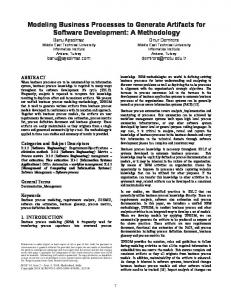
Even when using a visual modeling language such as UML, a useful specification of a business system is based on precisely defined design artifacts, rather than on diagrams. The design artifact determines the information about the business system, and the diagram is a representation of the design artifact. Some design artifacts are represented graphically in UML, some are represented by text or tables and some can be represented in a number of different ways. For example, the class lifecycle can be represented by a statechart diagram, an activity diagram, state transition table or in Backus-Naur form. The object interactions can be represented by sequence diagrams or by collaboration diagrams. The class responsibility is represented by text. Business processes, in UML shown as use cases, are considered as collaborations between organizations, business objects, actors, workers or other instances in a business system. Business process (use case) is a type of collaboration, specifying the collaboration responsibility, goal, precondition, postcondition and operations involved in the collaboration. Business process instance (use case instance) is an instance of collaboration, specifying concrete sequences of actions and events. Fig. 1 shows relationships between design artifacts specifying business processes and logical design of the software system. Artifacts are structured according to the level of abstraction: the organizational level, the system level and the architectural level. At each level of abstraction and in each view, the system can be described by four artifacts. They are the classifier model (specifying static relationships between classifiers), the classifier interaction model (specifying dynamic interactions between classifiers), the classifier (specifying classifier responsibilities, roles and static properties of classifier interfaces) and the classifier lifecycle (specifying dynamic properties of classifier interfaces). The classifier model is represented by a static structure diagram (if classifiers are objects, classes or interfaces), a use case diagram (if classifiers are use cases and actors), a deployment diagram (if classifiers are nodes) and a component diagram in its type form (if classifiers are components). The classifier interaction model is
represented by a sequence or collaboration diagram. The classifier is represented by text. The classifier lifecycle is represented by a statechart, an activity diagram, a state transition table and in Backus-Naur form.
Organizational Level
Business Objects View (Logical View)
Organization Model
Business Process View (Use Case View in UML)
Organization Interaction Model
«instance»
System Level
Organization Use Case Interaction Model
Organization Use Case
Organization Use Case Lifecycle
«collaborations» Organization
Organization Lifecycle «realize»
«refine»
System Model
System Interaction Model
«instance»
«refine» System Use Case Model
System Use Case Interaction Model
System Use Case
System Use Case Lifecycle
«collaborations» System / Actor
System / Actor Lifecycle «realize»
«refine» Architectural Level
Organization Use Case Model
Subsystem Model
Subsystem Interaction Model
«instance»
«refine» Subsystem Use Case Model
Subsystem Use Case Interaction Model
«collaborations» Subsystem
Subsystem Lifecycle
Subsystem Use Case
Subsystem Use Case Lifecycle
Fig. 1. Mapping business processes to objects at organizational, system and architectural levels.
The organizational level of abstraction specifies the responsibility of an organization (such as a company) and the business context of the organization. The artifact organization specifies responsibility and relevant static properties of the organization. The artifact organization model specifies relationships of the organization to other organizations. The artifact organization use case specifies the business process with the organizational scope in terms of the process goal, precondition, postcondition, business rules that the process must meet and other relevant static properties of the process. This business process is a collaboration of the organization with other organizations. All collaborations of the organization with other organizations are described in the artifact organization use case model, see the dependency «collaborations» in Fig. 1. The instances of organization business processes are specified in the artifact organization interaction model in terms of the interactions of the organization with other organizations. The organization business processes can be refined into more concrete system business processes, see the dependency «refine» in Fig. 1. Allowable order of the system business processes is
specified in the artifact organization use case life cycle. The organization use case interaction model specifies typical sequences of business process instances, see the dependency «instance» in Fig. 1. This artifact can be represented in UML by sequence or collaboration diagram, in which classifier roles are use case roles. An example of such a diagram is in the reference [2]. The realization of the organizational business process is specified by the interactions between the software system and its users (team roles) see the dependency «realize» in Fig. 1. The system level specifies the context of the software system and its relationships to its actors. The artifact system specifies the system interface, the system operations with responsibilities, preconditions, postconditions, parameters and return values. The artifact actor specifies the actor responsibilities and interfaces, if they are relevant. The system lifecycle specifies the allowable order of system operations and events. The system model specifies relationships between the software system and actors (other systems or users), and the system interaction model specifies interactions between the software system and actors. These interactions are instances of system business processes, see the dependency «instance» in Fig. 1. The artifact system use case specifies the static properties of the business process with the system scope. This business process is a collaboration of the system with other systems and users. All collaborations of the system with its actors are described in the artifact system use case model, see the dependency «collaborations» in Fig. 1. The dynamic properties of the business process interface, such as the allowable order of system operations in the scope of the business process, are specified in the system use case life cycle. The system use case interaction model specifies typical sequences of business process instances. The system business processes can be refined into subsystem business processes, see the dependency «refine» in Fig. 1. The realization of the system business process is specified by the subsystems at the architectural level, their responsibilities and interactions, see the dependency «realize» in Fig. 1. Artifacts at the architectural level are structured in the very same way. The architectural level specifies the software system in terms of subsystems and components, their responsibilities, relationships, interactions and lifecycles. The same structure can also specify the software system at the class level and the procedural level of abstraction. Please see reference [1] for examples of UML diagrams representing the artifacts discussed in this paper.
References 1. Hruby, P.: "Structuring Design Deliverables with UML", ’98, Mulhouse, France, 1998, http://www.navision.com/default.asp?url=services/methodology/default.asp 2. Hruby, P.: "Structuring Specification of Business Systems with UML", OOPSLA'98 workshop on behavioral semantics of OO business and system specifications, Vancouver, Canada, 1998. http://www.navision.com/default.asp?url=services/methodology/default.asp


![Business Diagram - Mind Mapping Software Blog [PDF]](https://m.moam.info/img/260x300/business-diagram-mind-mapping-software-blog-pdf_649661f8098a9e503c8b459c.jpg)


