UML Design Patterns for Business Processes Peter Rittgen* and Klaus Turowski+ *Information Systems Group II, Technical University Darmstadt, Hochschulstr. 1, 64289 Darmstadt, Germany, phone: +49(6151)16-4416, fax: -5162 E-mail:
[email protected] +
University of Augsburg, Chair of Business Information Systems, Universitätsstraße 16, 86135 Augsburg, Germany, phone: +49(821)598-4431, fax: -4432 E-mail:
[email protected]
ABSTRACT Today, modeling business processes and modeling software is done using different notations that are designed to fit to the special needs of the respective tasks. However, this fact results in a painful methodological gap between business models and software models, which is hard to bridge. This problem becomes even more painful if we try to build software to support certain business models as a smooth transition between the employed notations is mostly not supported or – due to methodological problems – impossible. In order to allow for a smoother transition we propose using Unified Modeling Language (UML) activity diagrams in both worlds. We show how this is done by deriving the transition of important (business) process patterns from Event-driven Process Chains (EPC) to UML activity diagrams.
1 MOTIVATION When analyzing a company for potentials of information systems support, a major task consists in identifying the relevant business processes and describing them in a suitable modeling language. Many such languages have been developed over the years such as IDEF (Integrated DEFinition, (Bruce, 1992)), Role Activity Diagrams (Ould, 1995) and ARIS/EPC (ARchitecture of integrated Information Systems / Event-driven Process Chain, (Scheer, 1999)) to name but a few. They share a common characteristic in that they are not equipped to support the design of software. The Unified Modeling Language (UML), cp. e.g. (Rational Software et al., 1997), on the other hand, does provide the features pertinent to software engineering but it is less qualified for domain-oriented models. In practice this leads to a separation of concerns but also to heterogeneous notation usage: domain experts using business languages, and software engineers using UML notations. This entails an undesirable gap between domain and software models representing a source of mistakes that are hard to correct. Hence we suggest a way of using only UML activity diagrams in both worlds taking a closer look at typical business processes modeled as EPCs and identifying recurring patterns which we then translate into UML. We show that the resulting UML patterns are suitable for designing processes not only in the software but also in the business domain.
-1-
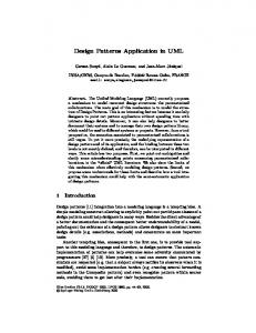
2 SEMANTICS OF UML ACTIVITY DIAGRAMS If we intend to express typical business process patterns as activity diagrams we have to go into the precise meaning of these diagrams first. Activity diagrams are defined in (OMG, 2000) as a variation of state machines where each state represents the performance of an activity. It is drawn as a rectangle with rounded vertical lines. The state contains a do activity and optionally an entry and/or an exit action. Entry and exit actions are performed on entering or leaving the state respectively. Their execution is considered to be instantaneous. The do activity is performed while being in the state. It can take any amount of time. Upon termination of this activity the state is left. Figure 1 shows a generic activity state together with its semantics in Petri net notation. A Petri net is a bipartite graph of places (circles) and transitions (squares) where a transition can fire if all incoming places are occupied by tokens. Upon firing a token is removed from each incoming place and thereafter one token is put on each outgoing place. See (Peterson, 1981) for a detailed treatment of Petri nets. In the Petri net of figure 1 the entry action is performed (on entering the state) and a token put on the place. While the activity is performed the token remains on the place. Upon its termination (which coincides with performing the exit action) the token is removed.
Figure 1: Activity state (notation and semantics)
If we would like to express non-sequential behaviour there are two different ways of splitting the path of execution: branching into alternative paths and forking into parallel paths. The branch is simply denoted by more than one arrow leaving a state (see figure 2). A guard should be specified to determine which path is selected. A guard is a Boolean condition written in square brackets. If it evaluates to true the corresponding path is chosen. An else guard can be specified which holds if all other guards are false. It should in fact be present if such a situation can arise to prevent the process from blocking. Exactly one path is chosen so the branch corresponds to the exclusive OR (XOR) connector of EPCs (see section 3.1). If more than one guard is true one of the associated paths is selected arbitrarily. To avoid misinterpretation in this case it is recommended to cascade the decisions in the form of a binary tree as shown in figure 3.
Figure 2: Guarded branch (notation and semantics)
-2-
The notational element for cascading guards is the diamond shape. It has no semantics of its own and only serves as an anchor point for splitting a path. The design in figure 3 ensures that condition A is given preference if both A and B are true.
Figure 3: Cascaded branch
The second way of splitting up the execution is the fork. It is denoted by a bar (see figure 4). If it is unguarded it simply refers to the parallel, independent execution of both paths (called thread 1 and thread 2). In this case it corresponds to the AND connector of EPCs. The join of the parallel paths is synchronous, i.e. it waits for the completion of both paths. If a path is guarded and the guard is false it is neither taken nor waited for. A fork where all paths are guarded corresponds to the (inclusive) OR connector of EPCs as arbitrarily many paths can be taken. The rules governing activity diagrams demand that guarded threads have to be wellnested, i.e. jumps into or out of such a thread are not allowed except for synchronizing between threads. Please observe that this restriction is problematic in the case of business process modeling as it drastically limits the number of valid models. A detailed discussion of this problem in the context of EPCs can be found in (Rittgen, 2001).
Figure 4: Guarded fork (notation and semantics)
3 TRANSLATING PROCESS PATTERNS INTO ACTIVITY DIAGRAMS 3.1
Typical Patterns in Business Processes
Having a strong background in business process reengineering projects, we observed some basic process patterns that occurred in most business processes (and that are as well documented in literature, e.g. (Rosemann, 1996), (Becker & Schütte, 1996)). In the following, we discuss the most important ones. We use EPCs to explain each of the process patterns. In doing so we employ a notation that is often used in typical business process reengineering projects in many European countries. Pattern 1: Dissection of events By definition, each function of an EPC is triggered by (at least) one event. E.g. the function Process customer order in figure 5 is triggered by an event called Customer order arrived. A -3-
situation like this (business function triggered by a single event) is typical for business process models in early stages. Later, as the underlying business processes become more transparent for the people who are in charge of modelling, the model often becomes more detailed, e.g. by subdividing the single start event into different starting events. In figure 5 we find such a pattern. In order to express that a business function may be triggered by different starting events, we join the new (detailed) starting events, which together replace the old starting event, by a logical connector, e.g. inclusive or exclusive disjunction.
Figure 5: Dissection of events
Pattern 2: Sequential events In EPCs events and functions alternate. This may lead to problems if events are sequentially ordered and need to occur in conjunction to trigger a specific business function. We give such an example in figure 6. In an EPC we can only express that both events together trigger the recording of the arrived goods but not the order in which the events occur i.e. that the order is submitted first and then the goods arrive.
Figure 6: Sequential events
Due to length restrictions we omit the remaining patterns. -4-
3.2
UML Activity Diagram Equivalents of the Patterns
In section 3.1 we identified a number of important patterns that typically arise when we model business processes. In many re-engineering projects we managed to acquire a deeper understanding of how certain patterns are meant to be understood in the case of EPCs. If we put this information together with the precise semantics of the UML activity diagrams as defined in (OMG, 2000) and set forth in section 2, we arrive at the UML patterns for business processes outlined in this section. We thereby show how process patterns that frequently occur in many business scenarios and which in most cases are given in a semi-formal way can be transformed into a rigorous representation that facilitates the development of software.
Figure 7: Dissection of events in UML
Figure 7 shows the UML pattern for the dissection of events. “Process customer order” becomes an activity in an activity state. Events in activity diagrams are represented as labels on the corresponding transition. This implies that the event triggers the transition from the preceding to the succeeding state. The detailed events in the EPC pattern of figure 5 are merged by an inclusive OR connector. As mentioned in section 2 it is equivalent to a guarded fork. Contrary to an EPC where multiple starting events are allowed, an activity diagram always has exactly one entry point, the initial state drawn as a full black circle. This means that the single entry path has to be split first into three parallel threads, one for each channel used for transmitting an order. Parallel threads are required because we want to allow that the same order is sent over more than one channel, e.g. as a phone call accompanied by a fax. The guards ensure that the function “process customer order” only waits for the channels that are actually used.
-5-
Figure 8: Sequential events in UML
The rules of EPCs require processes and events to alternate strictly: no two events may follow each other immediately. This prevents us from expressing a situation where a process is triggered by two consecutive events in a natural way. In activity diagrams there is no such restriction. As a consequence we simply insert a pseudo-state between the events (see figure 8). In this way we can specify that both events are required for the execution of the process and also the order in which they occur.
REFERENCES Becker, J., & Schütte, R. (1996). Handelsinformationssysteme. Landsberg. Bruce, T. A. (1992). Designing quality databases with IDEF1X information models. New York: Dorset House. Keller, G., & Teufel, T. (1997). SAP R/3 prozeßorientiert anwenden: iteratives ProzeßPrototyping zur Bildung von Wertschöpfungsketten. (2. ed.). Bonn: Addison-WesleyLongman. OMG (Ed.). (2000). OMG Unified Modeling Language Specification: Version 1.3, March 2000. Needham: OMG. Ould, M. (1995). Business processes: modeling and analysis for re-engineering and improvement. Chichester: John Wiley and Sons. Peterson, J. L. (1981). Petri net theory and the modeling of systems. Englewood Cliffs: Prentice-Hall. Rational Software, Microsoft, Hewlett-Packard, Oracle, Sterling Software, MCI Systemhouse, Unisys, ICON Computing, IntelliCorp, i-Logix, IBM, ObjecTime, Platinum Technology, Ptech, Taskon, Reich Technologies, & Softeam. (1997). UML Notation Guide: Version 1.1, 1 September 1997. Available: http://www.rational.com/uml [1999, 04-17]. Rittgen, P. (2001). E-Commerce Software: From Analysis to Design. In: Gangopadhyay, Aryya: Managing Business with Electronic Commerce: Issues and Trends. Hershey, PA: Idea Group, 2001. In A. Gangopadhyay (Ed.), Managing Business with Electronic Commerce: Issues and Trends (pp. 17-36). Hershey: Idea Group. Rosemann, M. (1996). Komplexitätsmanagement in Prozeßmodellen: Methodenspezifische Gestaltungsempfehlungen für die Informationsmodellierung. Wiesbaden: Gabler. -6-
Scheer, A.-W. (1999). ARIS - Business Process Modeling. (2 ed.). Berlin: Springer.
-7-


![[PDF] Business Modeling With UML: Business Patterns ... - Google Sites](https://m.moam.info/img/260x300/pdf-business-modeling-with-uml-business-patterns-g_647801cf097c4786708c57a7.jpg)


