Sep 23, 2013 - Center for Reliable and High-âPerformance Computing. September 8, 2013 ..... Here, we call our second-â ... This operation does not influence the solution of tridiagonal solver, but might cause overflow of CF-âLU. However ...
Mapping Tridiagonal Solvers to Linear Recurrences Li-‐Wen Chang, and Wen-‐mei Hwu {lchang20, w-‐hwu}@illinois.edu
IMPACT Technical Report IMPACT-‐13-‐01 University of Illinois at Urbana-‐Champaign Center for Reliable and High-‐Performance Computing September 8, 2013 Revision: September 23, 2013 Abstract In this report, we summarize existing parallel algorithms for tridiagonal solvers and propose a novel tridiagonal solver algorithm, called LUL-‐UBD algorithm. We point out all existing algorithms can be viewed as linear recurrences or extension of linear recurrences. We further indicate necessary optimization strategies for high-‐performance implementation of each algorithm in SIMD architectures. We also analyze the performance of existing algorithms, using computation complexity, the required number of parallel steps, the required number of division operations, and the number of memory access requests. Our proposed algorithm has the minimal number of memory access requests, the minimal number of division operations, and linear computational complexity. Key terms: Cyclic Reduction, Block Cyclic Reduction, Parallel Cyclic Reduction, SPIKE algorithm, Tridiagonal Solvers, LU-‐decomposition, Linear recurrence 1. Introduction The tridiagonal solver is a very important building block in a wide range of engineering and scientific applications, including computer graphics [1][2][3], fluid dynamics [2][4][5], Poisson solvers [6], preconditioners for iterative solvers [7], cubic spline interpolation [8], and semi-‐coarsening [9][10] for multi-‐grid methods. In order to achieve high throughput, several parallel tridiagonal algorithms were proposed, including Cyclic Reduction (CR) [12], Parallel Cyclic Reduction (PCR) [12], Recursive Doubling (RD) [13], and the SPIKE algorithm [14][15]. In this report, we first use the first-‐order and second-‐order linear recurrence to explain the above algorithms. We show all existing tridiagonal algorithms are able to be viewed as linear recurrences or are related to the linear recurrences. Based on that, we further propose a tridiagonal algorithm using only linear recurrences. Then, we compare the proposed algorithm with the existing algorithms and show the effectiveness of the proposed algorithm by using computation complexity, the required number of parallel steps, the required number of division operations, and the number of memory access
requests. The reason using the required number of division operations is that division is the most expensive operation in a tridiagonal solver, and the reason using memory access requests is that the tridiagonal solver is a memory-‐bound application in modern SIMD architectures. In this report, we do not target algorithms on any architecture, like GPU or CPU. We tend to make our analysis and discussion general to fit any SIMD architectures. Since no every operation has equivalent cost, and the relationship of costs might vary from architecture to architecture, optimization strategies might vary from architecture to architecture. In our analyses, computation complexity, the required number of parallel steps, the required number of division operations, and the number of memory access requests are all used for comparing performance. 2. Background for Related Existing Algorithms The tridiagonal solver is a solver to find a solution of Ax=d, where A is an n-‐by-‐n matrix tridiagonal matrix and d is an n-‐entry vector as listed in Eq 1. Here, we summarize five classical algorithms, including the Thomas algorithm [11], CR, PCR, RD, and SPIKE algorithms. While only the Thomas algorithm is a sequential algorithm, the rest are parallel algorithms. ⎡b0 ⎢ a ⎢ 1 ⎢ A = ⎢ ⎢ ⎢ ⎢ ⎢⎣
c0 b1 a2
c1 b2
c2 an−2
bn − 2 a n −1
⎤ ⎡ d 0 ⎤ ⎥ ⎢ d ⎥ ⎥ ⎢ 1 ⎥ ⎥ ⎢ d 2 ⎥ (1) ⎥, d = ⎢ ⎥ ⎥ ⎢ ⎥ ⎢d n −2 ⎥ cn −2 ⎥ ⎥ ⎢ ⎥ bn −1 ⎥⎦ ⎢⎣ d n −1 ⎥⎦
2.1 Thomas Algorithm The Thomas algorithm is a reduced case of Gaussian elimination (or LU-‐decomposition/solver) for a tridiagonal matrix and consists of two phases, a forward reduction and a backward substitution as shown in Eq. 2 and 3. The forward reduction eliminates the lower diagonal sequentially, while the backward substitution solves unknown variables sequentially using the resultant upper and main diagonals. c0 ci , ciʹ′ = , i = 1,2,..., n − 1 b0 bi − ciʹ′−1ai (2) d0 d i − d iʹ′−1ai d 0ʹ′ = , d iʹ′ = , i = 1,2,..., n − 1 b0 bi − ciʹ′−1ai
c0ʹ′ =
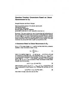
xn = d nʹ′ , xi = d iʹ′ − ciʹ′xi+1 , i = n − 1, n − 2,...,1 (3) 2.1. Cyclic Reduction The CR algorithm is an odd-‐even reduction, and known as a two-‐way elimination for a tridiagonal matrix. There are also two phases, forward reduction and backward substitution, in CR. In each step of forward reduction, each odd (or even) equation is eliminated by using adjacent two equations, and, after removing redundant unknown variables and zeros, a half-‐size system is formed of the resultant new equation. Fig. 1 illustrates one step of forward reduction in a 4-‐by-‐4 matrix. In this case, 𝑎! and 𝑐! in the equation 𝑒! is eliminated by 𝑒! and 𝑒! using Eq. 4, but 𝑎!! is propagated from 𝑎! in 𝑒! . After that, a new row 𝑒!! is formed. Similarly, 𝑒!! is generated by eliminating 𝑒! with 𝑒! . After that, 𝑒!! and 𝑒!! can form a new matrix with the half size. ⎡b0 ⎢a ⎢ 1 ⎢ ⎢ ⎣
c0 b1 a2
c1 b2 a3
⎤ ⎡ b0ʹ′ ⎥ ⎢ a ⎥ → ⎢ 1 c2 ⎥ ⎢a2ʹ′ ⎥ ⎢ b3 ⎦ ⎣
0 b1 0 0
c0ʹ′ c1 b2ʹ′ a3
⎤ ⎥ ʹ′ ⎥ ⇒ ⎡ b0 0 ⎥ ⎢⎣a2ʹ′ ⎥ b3 ⎦
c0ʹ′ ⎤ b2ʹ′ ⎥⎦
Figure 1. A forward reduction step of CR in a 4-‐by-‐4 matrix
aiʹ′ = −ai −stride k1 , biʹ′ = bi − ci −stride k1 − ai + stride k 2 ciʹ′ = −ci −stride k 2 , d iʹ′ = d i − d i −stride k1 − d i + stride k 2 (4) , where k1 =
ai bi −stride
, k2 =
ci bi + stride
In each step of the backward substitution, unknown variables can be solved by substituting solutions of the smaller system using Eq. 5.
xi =
di − aiʹ′xi − stride − ciʹ′xi + stride (5) biʹ′
Figure 2. The graph representation of CR for an 8-‐by-‐8 matrix.
Fig. 2 shows the graph representation of CR for an 8-‐by-‐8 matrix. Here, we intentionally use 2 colors, red and blue, to label edges. It might be surprising that all red edges form a Brent-‐Kung circuit [16] (Fig. 3) and all blue edges form another reverse Brent-‐Kung circuit. In Fig. 4, we intentionally split red and blue in each step to make it easier to be observed. However, it is not a coincidence to have a Brent-‐Kung circuit in CR. A tridiagonal matrix can be split into one lower bidiagonal matrix and an upper bidiagonal matrix easily. A lower bidiagonal solver can be easily represented as a first-‐order linear recurrence, and an upper bidiagonal matrix can be considered as a reverse first-‐order linear recurrence. The Brent-‐Kung circuit is a common algorithm for a first-‐order linear recurrence. Therefore, CR can be considered as a specialized extension of Brent-‐Kung circuit.
Figure 3. The Brent-‐Kung circuit with 8 nodes
Figure 4. The graph representation of CR for an 8-‐by-‐8 matrix with split red and blue edges
2.2. Parallel Cyclic Reduction The PCR algorithm is a modification of CR. In contrast to CR, PCR performs only reductions, using Eq. 4, on both even AND odd equations. Fig. 5 shows an example for 1 step PCR for a 4-‐by-‐4 tridiagonal matrix. After reductions, two independent sets of even and odd equations can be considered as two independent sub-‐tridiagonal matrices. Most previous works [17][18] used this characteristic to split a large tridiagonal matrix into multiple smaller tridiagonal matrices for more parallelism. ⎡b0 ⎢a ⎢ 1 ⎢ ⎢ ⎣
c0 b1 a2
c1 b2 a3
⎤ ⎡b0ʹ′ ⎥ ⎢ ⎥ → ⎢ 0 ⎢a2ʹ′ c2 ⎥ ⎥ ⎢ b3 ⎦ ⎣
0 b1ʹ′ 0 a3ʹ′
c0ʹ′ 0 b2ʹ′ 0
⎤ c1ʹ′ ⎥⎥ ⇔ 0 ⎥ ⎥ b3ʹ′ ⎦
⎡b0ʹ′ ⎢aʹ′ ⎣ 2 ⎡ b1ʹ′ ⎢aʹ′ ⎣ 3
c0ʹ′ ⎤ b2ʹ′ ⎥⎦ c1ʹ′ ⎤ b3ʹ′ ⎥⎦
Figure 5. A forward reduction step of PCR in a 4-‐by-‐4 matrix Fig. 6 shows the graph representation of PCR for an 8-‐by-‐8 matrix. Here, as we do for CR, we also use 2 colors to label edges. As expected, we can see all red edges form a Kogge-‐Stone circuit [19] (Fig. 7) and all blue edges form another bit-‐reversal Kogge-‐Stone circuit. Considering the Kogge-‐Stone circuit is also a common algorithm for a first-‐order linear recurrence, it seems obvious. Therefore, PCR can be considered as a specialized extension of the Kogge-‐Stone circuit.
Figure 6. The graph representation of PCR for an 8-‐by-‐8 matrix.
Figure 7. The Kogge-‐Stone circuit with 8 nodes 2.3. Recursive Doubling The RD algorithm is a parallel tridiagonal solver by formulating a tridiagonal matrix into a second-‐order linear recurrence (Eq. 6) with an unknown variable ( x0 ). By applying a linear recurrence solver, the
relationship, xi = βi − αi ⋅ x0 , between an unknown variable xi and x0 can be determined, and x0 can be also solved. After x0 is solved, an unknown variable xi can be easily solved by applying substitution with x0 . This substitution can be considered as a broadcast, since all unknown variables xi ' s require x0 .
⎡ 1 ⎢b c 0 ⎢ 0 ⎢a1 b1 c1 ⎢ ⎢ ⎢ an−2 ⎢ ⎣⎢
bn −2
cn−2
a n−1
bn −1
⎤ ⎡ x0 ⎤ ⎡ x0 ⎤ ⎡ 1 ⎥ ⎢ x ⎥ ⎢ d ⎥ ⎢b / c ⎥ ⎢ 1 ⎥ ⎢ 0 ⎥ ⎢ 0 0 ⎥ ⎢ x2 ⎥ ⎢ d1 ⎥ ⎢ a1 / c1 ⎥ ⎢ ⎥ ⇒ ⎢ ⎥ = ⎢ ⎥ ⎢ ⎥ ⎢ ⎥ ⎢ ⎥ ⎢ xn −1 ⎥ ⎢d n −2 ⎥ ⎢ ⎥ ⎢ ⎥ ⎢ ⎥ ⎢ 1⎦⎥ ⎣⎢ 0 ⎦⎥ ⎣⎢ d n −1 ⎦⎥ ⎣⎢
1 b1 / c1
1 an−2 / cn−2
bn −2 / cn −2
1
a n −1
bn −1
x0 ⎤ ⎡ x0 ⎤ ⎡ ⎤ ⎥ ⎢ x ⎥ ⎢ d / c ⎥ 0 0 1 ⎥ ⎢ ⎥ ⎥ ⎢ ⎥ ⎢ x2 ⎥ ⎢ d1 / c1 ⎥ = ⎥ ⎢ ⎥ ⎥ ⎢ ⎥ ⎢ ⎥ ⎢ ⎥ ⎥ ⎢ xn −1 ⎥ ⎢d n−2 / cn −2 ⎥ ⎥ ⎢ ⎥ ⎥ ⎢ 1⎦⎥ ⎣⎢ 0 ⎦⎥ ⎣⎢ d n−1 ⎦⎥
(6)
2.4. SPIKE algorithm The SPIKE algorithm is a domain decomposition algorithm, and it decomposes a banded matrix into a set of disjoint matrices that can be solved independently. We describe a specialized SPIKE algorithm for tridiagonal matrices. In the tridiagonal solver (Fig. 8), AX=F, the matrix A can be partitioned in several diagonal blocks Ai and off-‐diagonal single elements Bi and Ci. Similarly, X and F can be partitioned into corresponding parts.
A=
A1
B1
C2
A2
B2
C3
A3
B3
X3
C4
A4
X4 ,
X=
,
X1
F1
X2
F2
F=
F3 F4 .
Figure 8. Partition for a tridiagonal matrix in the SPIKE algorithm
Further, we can define D and S satisfying A=DS, where D is just the diagonal blocks of A and S has the structure in Fig. 9.
A1 D=
A2
I
V1
W2
I
V2
W3
I
V3
W4
I
S=
A3 A4
,
Figure 9. Definition of D and S in the SPIKE algorithm
.
Here, Vi and Wi satisfy Eq. 7.
(7) , . Therefore, AX=F can be easily solved by resulting in DY=F and SX=Y. Since D is block-‐diagonal, each block can be solved independently. SX=Y can be solved by a unit block tridiagonal solver. Most existing works use a specialized Block Cyclic Reduction (BCR) for solving SX=Y. Only two variables in each block are required to be solved for other blocks. A reduced matrix is required to be solved. We refer readers to the works of Pollizi [14][15]. In this report, we also propose an alternative using “Block Parallel Cyclic Reduction” (BPCR) to solve the unit block tridiagonal solver with the reduced matrix in appendix. We point out the SPIKE algorithm shares a lot of similarities with the group-‐structure algorithms [X] in first-‐order linear recurrences. The group-‐structure algorithms also decompose a first-‐order linear recurrence to several independent local first-‐order linear recurrences. After solving all local first-‐order linear recurrences, group-‐structure algorithms also solve a reduced first-‐order linear recurrence. 3. Proposed Algorithm We propose a tridiagonal algorithm using only linear recurrences. As we mentioned, a tridiagonal matrix can be split into two bidiagonal matrices, and each bidiagonal solver can be viewed as a first-‐order linear recurrence. Therefore, we split the tridiagonal matrix into two bidiagonal matrices, and solve just using two linear recurrences one after the other. Here, a parallel LU-‐decomposition is applied for generating the lower and upper bidiagonal matrices. We consider A=LU, and L and U are defined in Eq. 8. ⎡b0ʹ′ ⎢ a ⎢ 1 ⎢ L = ⎢ ⎢ ⎢ ⎢ ⎣⎢
b1ʹ′ a2
b2ʹ′
an−2
bnʹ′ −2 an−1
⎤ ⎡1 c0 / b0ʹ′ ⎢ ⎥ 1 ⎢ ⎥ ⎢ ⎥ ⎥, U = ⎢ ⎢ ⎥ ⎢ ⎥ ⎢ ⎥ bnʹ′ −1 ⎦⎥ ⎣⎢
c1 / b1ʹ′ 1 c2 / b2ʹ′
⎤ ⎥ ⎥ ⎥ (8) ⎥ ⎥ 1 cn−2 / bnʹ′ −2 ⎥ ⎥ 1 ⎦⎥
Ax=d can be easily solved by resulting in Ly=d and Ux=y. Simply multiplying L and U, we can have Eq. 9 and 10.
b0ʹ′ = b0 (9), biʹ′ = bi −
ai ci −1 . (10) biʹ′−1
By applying continued fractions with second-‐order linear recurrence, we can define the following with second-‐order linear recurrence (Eq. 11 and Eq. 12).
⎡ 1 ⎢− b ⎢ 0 ⎢a1c0 ⎢ ⎢ ⎢ ⎢ ⎢⎣
1 − b1
1 an−2 cn−1
− bn−2
1
an−1cn−2
− bn−1
biʹ′ = bi −
⎤ ⎡ θ −1 ⎤ ⎡1⎤ ⎥ ⎢ θ ⎥ ⎢0⎥ ⎥ ⎢ 0 ⎥ ⎢ ⎥ ⎥ ⎢ θ1 ⎥ ⎢0⎥ ⎥ ⎢ ⎥ = ⎢ ⎥ (11) ⎥ ⎢ ⎥ ⎢ ⎥ ⎥ ⎢θ n−2 ⎥ ⎢0⎥ ⎥ ⎢ ⎥ ⎢ ⎥ 1⎥⎦ ⎢⎣θ n−1 ⎥⎦ ⎢⎣0⎥⎦
θ i −2 ai ci −1 θ i . (12) = θ i −1 θ i−1
Our LU-‐decomposition actually is a continued-‐fraction LU (CF-‐LU) decomposition [20] with a unit upper bidiagonal matrix. After each biʹ′ is computed, we can simply solve Ly=d and save ci / biʹ′ on-‐the-‐fly. More clearly, we fuse CF-‐LU with the bidiagonal solver for Ly=d. Considering only 1 / biʹ′ is needed for computing both Ly=d and
ci / biʹ′ , we can simply compute
1 θ i −1 to save division operations. After Ly=d solved, x can be simply = biʹ′ θ i
solved by solving Ux=y. Here, we use one second-‐order linear recurrence (Eq. 11) and two first-‐order linear recurrences (Ly=d and Ux=y). However, since kernel fusion is applied, only one second-‐order linear recurrence and one first-‐order linear recurrence are really computed. Here, we call our second-‐ order linear recurrence LUL (LU-‐decomposition with lower bidiagonal solver) and the first-‐order linear recurrence UBD (upper bidiagonal solver). Our method is named as LUL-‐UBD. Compared to the RD algorithm, our LUL-‐UBD algorithm has several benefits. First, RD uses division operations with ci ' s . Since ci may be zero or much smaller than bi or ai in a general matrix and even a diagonally dominant matrix, RD tends to have more numerical errors. Second, While RD includes one second-‐order linear recurrence and one broadcast, LUL-‐UBD contains one second-‐order linear recurrence and two first-‐order linear recurrences. It seems that LUL-‐UBD might be slower than RD. However, in LUL-‐UBD, one first-‐order linear recurrence can be fused with the second-‐order linear recurrence to avoid redundant memory access. If we consider a first-‐order linear recurrence is memory-‐ bound in most modern SIMD architecture, its performance is similar to the performance of broadcast, which is also memory-‐bound. The CF-‐LU algorithm has its own limitations. Since diagonal values in Eq. 11 are all 1’s, which are not dependent on coefficients of tridiagonal matrix, it might cause overflow when those coefficients are
very big. For example, for a given i, we can simply multiply ai , bi , ci , and d i by a very large number. This operation does not influence the solution of tridiagonal solver, but might cause overflow of CF-‐LU. However, it is also very simple to avoid this overflow issue by performing normalization of each row. Therefore, in general, LUL-‐UBD is more robust than RD. 4. Tiling Optimization and Algorithm Analysis In this section, we discuss about tiling optimization, which is necessary for high-‐performance implementation in most SIMD architectures. Before we make a detailed discussion, we define our SIMD architecture and the problem size to guarantee a fair comparison. Here, we assume the size of matrix is n. The vector length of a lock step in SIMD is M. M is much smaller than n. We also consider a cluster of vector processors. The number of vector processor is P. P is also much smaller than n. The largest size for data caching is L (L time data types). For example, if our data type is double and double is 8 Byte, our largest size for data caching is 8L Byte. Here, we also assume L is much smaller than n but L is larger than M (since the size of private cache is usually larger than the vector length). No multithreading exists in our defined vector processor for simplifying analyses. 4.1 Thomas Algorithm The Thomas Algorithm is a sequential algorithm, and it cannot benefit from SIMD architectures. The number of (sequential) steps of Thomas algorithm is 2n-‐1 and the computational complexity is O(n). The number of division is also 2n-‐1. The number of memory access requests includes 4n reads and 2n writes in the forward reduction and 2n reads and 1n writes in the backward substitution. In the Thomas algorithm with a large size n, since the forward reduction executes with a different order of the backward substitution, data used in the forward reduction are less likely to be cached for the backward substitution. (For data in the tail of forward reduction, data caching might be feasible.) Therefore, the total number of memory access requests around 9n. 4.2 Cyclic Reduction If an n-‐length vector machine is feasible, the required number of (parallel) steps is 2log(n). However, in practice, it might not be feasible. In our defined SIMD architecture, we consider an M-‐length vector processor and P numbers of vector processors. Since it is a cluster of processors, tiling optimization is necessary for minimizing the number of memory requests. Fig. 10 shows the graph representation of tiled CR. The bold blue lines are inter-‐tile communication of forward reduction and were also proposed as split operations in [21]. Similarly, we can also define the bold red lines as inter-‐tile communication for backward substitution after a global CR across all tiles. The numbers of inter-‐tile communication of forward reduction and backward substitution are both 4(n/T-‐1)log(T), where T is the tile size.
Considering the largest size for data caching is L and 4 coefficients are required for one equation, T is equal to L/4. Since tiled CR does not change the computation pattern, the computational complexity of tiled CR is still O(n) and the number of division is still 3n-‐log(n)-‐3. The required number of (parallel) steps in each tile is 2log(T) + log(T) + 1 if a T-‐length vector machine is feasible. While an-‐M length vector machine is applied and M is smaller than T, the required number of (parallel) steps is log 𝑇 + 1 + !!!"# (!) 2 !!!
∗ 𝑐𝑒𝑖𝑙(
! !! !
) . The number of (parallel) steps for the global CR can be considered as another
CR with an n/T problem size. The number of memory requests includes 8n reads, 8n+8n/T writes, 8(n/T -‐1)log(T) reads for inter-‐tile communication, and the memory requests of global CR, which is another CR with an n/T problem size. The lower bound of memory requests is 16n, and the upper bound is 18n.
global CR
Figure 10. The graph representation of tiled CR for an 8-‐by-‐8 matrix with tiles of 4-‐by-‐4 sub-‐matrices
Global BCR or BPCR for SPIKE
Figure 11. The graph representation of tiled CR with the SPIKE algorithm for an 8-‐by-‐8 matrix
Fig. 11 shows another possible tiling strategy, which can be considered as a hybrid of SPIKE and CR. In each tile, a complete CR is performed. After that, BCR or BPCR, which are mentioned in the section of SPIKE algorithm, is applied for reduced matrices. Then, broadcast operations are applied for completely solving each tile (each block in block tridiagonal). Here, we leave the analysis in the analysis of SPIKE algorithm. 4.3 Parallel Cyclic Reduction If an n-‐length vector machine is feasible, PCR requires log(n) (parallel) steps, O(n*log (n)) computational complexity, and 2nlog(n)-‐n+2 division operations. However, in our defined SIMD architecture, tiling is also necessary for a high-‐performance implementation. Fig. 12 shows the graph representation of tiled PCR, and it can be considered as a hybrid of SPIKE and PCR. Similar to the hybrid of SPIKE and CR, in each tile, a complete PCR is performed. After that, BCR or BPCR is applied for reduced matrices. Then, broadcast operations are applied for completely solving each tile. Here, we leave the analysis in the analysis of SPIKE algorithm.
Global BCR or BPCR for SPIKE
Figure 12. The graph representation of tiled PCR with the SPIKE algorithm for an 8-‐by-‐8 matrix 4.4 Recursive Doubling In RD, the computational complexity, the number of steps, and the number of memory requests are all dependent on algorithms for linear recurrences. The minimal computational complexity is O(n), and it happens in most linear recurrence algorithms. The minimal number of division is n, and it also happens in most linear recurrence algorithms. The number of steps varies a lot from algorithm to algorithm. The minimal number of steps is log(n)+2, and it requires the Kogge-‐Stone circuit with an n-‐length vector machine. In practice, a tiled linear recurrence has around T/M + log(M) steps and steps of the global linear recurrence with a n/T problem size, where T is tiling size and is L/3. The global linear recurrence is usually implemented with a sequential algorithm with inter-‐tile communication to minimize the number of memory requests for a high-‐performance implementation. The minimal number of memory requests of second-‐order linear recurrence contains 4n reads and 2n-‐1 writes (2n-‐2 writes for coefficients and 1 write for x0 ), while the minimal number of memory requests in broadcast contains 2n-‐1 reads and n-‐1 writes. Therefore, RD has around 9n memory access requests in minimum.
4.5 SPIKE algorithm The computational complexity, the number of steps, and the number of memory request in a SPIKE algorithm is all dependent on the parallel algorithm for solving sub-‐matrices (each tile). Three algorithms, which are the Thomas algorithm, CR (Fig. 11), and PCR (Fig. 12), are often applied. The minimal computational complexity is around O(n), and it happens when the complexity of the sub-‐matrix solver is also linear, such as CR or the Thomas algorithm. The SPIKE algorithm with Thomas algorithm has 2n+n/T division operations, while the SPIKE algorithm with CR has 3n-‐(n/T)*log(T)-‐n/T division operations. When PCR is applied for the sub-‐matrix solver, the complexity becomes O(nlog(T) + (n/T)*log(n/T) ), where T is tiling size and is equal to L/4. The SPIKE algorithm with PCR has 2nlog(T)-‐ n+4n/T division operations. Here, to make more clearly, the tiling size (T) of Thomas algorithm might be different from the tiling size of CR or PCR. The number of steps varies a lot from algorithm to algorithm, including both algorithms for the sub-‐ matrix solver and the block tridiagonal solver. When the Thomas algorithm is applied for the sub-‐matrix solver, 2T steps are required for each tile with T size. Since the Thomas algorithm does not need data tiling, we can simply maximize parallelism. Therefore, the minimal number of steps is 2n/M/P + log(M*P) +1, and it happens when BPCR are applied for the reduced block tridiagonal solver. When the Thomas algorithm is applied for the sub-‐matrix solver, 2log(T) steps are required for each tile with T size. Therefore, the minimal number of steps is 2log(T)+3log(n/T) +1, and also BPCR is applied. When PCR is applied, the minimal number of steps is log(T)+3log(n/T) +1, and also BPCR is applied. The minimal number of memory requests of all sub-‐matrix solvers includes 4n reads and 3n writes. The number of memory requests for the block tridiagonal solver varies from 4n to 4n + 15n/T, where T is tiling size. 4.5 LUL-‐UBD algorithm In LUL-‐UBD, similar to RD, the computational complexity, the number of steps, and the number of memory requests are all dependent on algorithms for linear recurrences. The minimal computational complexity, similar to RD, is O(n), and it happens in most linear recurrence algorithms. The minimal number of division is also n, and it also happens in most linear recurrence algorithms. In practice, a tiled LUL, which is a second-‐order linear recurrence fused with a first-‐order linear recurrence, has around 2T1/M + log(M) steps and steps of the global linear recurrence with a n/T1 problem size, where T1 is tiling size and T1 is L/4. The UBD, which is a first-‐order linear recurrence, has T2/M + log(M) steps and steps of the other global linear recurrence with a n/T2 problem size, where T2 is tiling size and T2 is L/2. Similar to RD, the global linear recurrences are usually implemented with a sequential algorithm with inter-‐tile communication to minimize the number of memory requests for a high-‐performance implementation. The minimal number of memory requests of LUL contains 4n reads and 2n writes, and the one of UBD contains 2n reads and n writes. Therefore, LUL-‐UBD has around 9n memory access requests in minimum.
5. Conclusion We propose a novel tridiagonal algorithm, called LUL-‐UBD, which only relies on linear recurrences. We further show all existing algorithms are related to linear recurrences. We also compare LUL-‐UBD with all existing algorithms, to demonstrate LUL-‐UBD has minimal number of memory requests and division operations. Reference [1] M. Kass, A. Lefohn, and J. Owens, “Interactive depth of field using simulated diffusion on a GPU,” Tech. Rep. #06-‐01, Pixar Animation Studios, Jan. 2006. http://graphics.pixar.com/library/DepthOfField. [2] M. Kass and G. Miller, “Rapid, stable fluid dynamics for computer graphics,” in Proceedings of the 17th annual conference on Computer graphics and interactive techniques, SIGGRAPH ’90, (New York, NY, USA), pp. 49–57, ACM, 1990. [3] S. Sengupta, M. Harris, Y. Zhang, and J. D. Owens, “Scan primitives for GPU computing,” in Graphics Hardware 2007, pp. 97– 106, Aug. 2007. [4] N. Sakharnykh, “Tridiagonal solvers on the GPU and applications to fluid simulation,” NVIDIA GPU Technology Conference, September 2009. [5] N. Sakharnykh, “Efficient tridiagonal solvers for ADI methods and fluid simulation,” NVIDIA GTC, Sep. 2010. [6] R. W. Hockney, “A fast direct solution of Poisson’s equation using Fourier analysis,” J. ACM, vol. 12, pp. 95–113, Jan. 1965. [7] A. Greenbaum, Iterative Methods for Solving Linear Systems. Philadelphia: SIAM, 1997. [8] L. Chang, M. Lo, N. Anssari, K. Hsu, N. Huang, and W. Hwu, “Parallel implementation of multi-‐dimensional ensemble empirical mode decomposition,” International Conference on Acoustics, Speech, and Signal Processing, May 2011. [9] M. Prieto, R. Santiago, D. Espadas, I. M. Llorente, and F. Tirado, “Parallel multigrid for anisotropic elliptic equations,” J. Parallel Distrib. Comput., vol. 61, pp. 96–114, January 2001. [10] D. Göddeke and R. Strzodka, “Cyclic reduction tridiagonal solvers on GPUs applied to mixed-‐precision multigrid,” IEEE Transactions on Parallel and Distributed Systems, vol. 22, pp. 22–32, 2011. rd
[11] S. D. Conte and C. W. D. Boor, Elementary Numerical Analysis: An Algorithmic Approach. McGraw-‐Hill Higher Education, 3 ed., 1980. [12] R. W. Hockney and C. R. Jesshope, Parallel computers : architecture, programming and algorithms. Hilger, Bristol, 1981. [13] H. S. Stone, “An efficient parallel algorithm for the solution of a tridiagonal linear system of equations,” J. ACM, vol. 20, pp. 27–38, Jan. 1973. [14] E. Polizzi and A. H. Sameh, “A parallel hybrid banded system solver: The SPIKE algorithm,” Parallel Computing, vol. 32, no. 2, pp. 177–194, 2006. Cited By (since 1996): 24. [15] E. Polizzi and A. Sameh, “SPIKE: A parallel environment for solving banded linear systems,” Computers and Fluids, vol. 36, no. 1, pp. 113–120, 2007. Cited By (since 1996): 15. [16] R. P. Brent and H. T. Kung “A Regular Layout for Parallel Adders,” IEEE Trans. Comput., Mar, 1982
[17] A. Davidson, Y. Zhang, and J. D. Owens, “An auto-‐tuned method for solving large tridiagonal systems on the GPU,” in Proceedings of the 25th IEEE International Parallel and Distributed Processing Symposium, May 2011. [18] H. Kim, S. Wu, L. Chang, and W. Hwu, “A scalable tridiagonal solver for gpus,” in Parallel Processing (ICPP), 2011 International Conference on, pp. 444 –453, Sept. 2011. [19] Peter M. Kogge, and Harold S. Stone. “A Parallel Algorithm for the Efficient Solution of a General Class of Recurrence Equations,” IEEE Trans. on Comput., v.22 n.8, p.786-‐793, Aug. 1973 [20] Ömer Eğecioğlu, “LU Factorization And Parallel Evaluation Of Continued Fractions,” Proceedings of IPDPS, 1998 [21] F. Argüello, D.B. Heras, M. Bóo, and J. Lamas-‐Rodríguez, “The split-‐and-‐merge method in general purpose computation on GPUs,” Parallel Computing, Volume 38, Issues 6–7, June–July 2012, pp. 277-‐288
Appendix The Block Parallel Cyclic Reduction (BPCR) algorithm is an extension of PCR for a block tridiagonal solver. Fig. A1 shows the classical PCR, while Fig. A2 shows a tiled PCR corresponding to the graph representation of Fig. 12. In Fig. A2, a 2-‐by-‐2 reduced matrix is solved for a 8-‐by-‐8 block tridiagonal matrix with a block size as 4-‐by-‐4. ⎡b0 ⎢a ⎢ 1 ⎢ ⎢ ⎢ ⎢ ⎢ ⎢ ⎢ ⎢ ⎣⎢
c0 b1 a2
c1 b2 a3
c2 b3 a4
c3 b4 a5
c4 b5 a6
c5 b6 a7
⎤ ⎡b0ʹ′ ⎥ ⎢ 0 ⎥ ⎢ ⎥ ⎢a 2ʹ′ ⎥ ⎢ ⎥ → ⎢ ⎥ ⎢ ⎥ ⎢ ⎥ ⎢ ⎥ ⎢ c6 ⎥ ⎢ b7 ⎦⎥ ⎣⎢
0 b1ʹ′ 0 a3ʹ′
⎤ ⎡ b0ʹ′ ⎥ ⎢ 0 ⎥ ⎢ ⎥ ⎢a 2ʹ′ ⎥ ⎢ ⎥ → ⎢ ⎥ ⎢ ⎥ ⎢ ⎥ ⎢ ⎥ ⎢ c6 ⎥ ⎢ b7 ⎥⎦ ⎢⎣
0 b1ʹ′ 0 a3ʹ′
c0ʹ′ 0 b2ʹ′ 0 a 4ʹ′
c1ʹ′ 0 b3ʹ′ 0 a5ʹ′
c2ʹ′ 0 b4ʹ′ 0 a6ʹ′
c3ʹ′ 0 b5ʹ′ 0 a7ʹ′
c4ʹ′ 0 b6ʹ′ 0
⎤ ⎡b0ʹ′ʹ′ ⎥ ⎢ 0 ⎥ ⎢ ⎥ ⎢ 0 ⎥ ⎢ ⎥ → ⎢ 0 ⎥ ⎢a 4ʹ′ʹ′ ⎥ ⎢ c5ʹ′ ⎥ ⎢ ⎥ ⎢ 0 ⎥ ⎢ b7ʹ′ ⎦⎥ ⎣⎢
0 0 b1ʹ′ʹ′ 0 0 b2ʹ′ʹ′ 0 0 0 0 a5ʹ′ʹ′ 0 a6ʹ′ʹ′
0 c0ʹ′ʹ′ 0 0 0 0 b3ʹ′ʹ′ 0 0 b4ʹ′ʹ′ 0
0
0 a7ʹ′ʹ′
0 0
⎤ ⎡b0ʹ′ʹ′ʹ′ ⎤ ⎥ ⎢ ⎥ c1ʹ′ʹ′ b1ʹ′ʹ′ʹ′ ⎥ ⎢ ⎥ ⎥ ⎢ ⎥ 0 c2ʹ′ʹ′ b2ʹ′ʹ′ʹ′ ⎥ ⎢ ⎥ 0 0 c3ʹ′ʹ′ ⎥ b3ʹ′ʹ′ʹ′ ⎢ ⎥ → ⎢ ⎥ 0 0 0 ⎥ b4ʹ′ʹ′ʹ′ ⎥ ⎢ ⎥ ʹ′ ʹ′ ʹ′ b5ʹ′ʹ′ 0 0 ⎥ b ⎢ ⎥ 5 ⎥ ⎢ ⎥ 0 b6ʹ′ʹ′ 0 b6ʹ′ʹ′ʹ′ ⎥ ⎢ ⎥ ʹ′ ʹ′ ʹ′ 0 0 b7ʹ′ʹ′ ⎦⎥ b 7 ⎥ ⎣⎢ ⎦
Figure A1. A forward reduction of PCR in a 8-‐by-‐8 matrix
⎡b0 ⎢a ⎢ 1 ⎢ ⎢ ⎢ ⎢ ⎢ ⎢ ⎢ ⎢ ⎢⎣
c0 b1 a2
c1 b2 a3
c2 b3 a4
c3 b4 a5
c4 b5 a6
c5 b6 a7
c0ʹ′ 0 b2ʹ′ 0
c1ʹ′ 0 b3ʹ′ a 4ʹ′ a5ʹ′
c 2ʹ′ c3ʹ′ b4ʹ′ 0 a6ʹ′
0 b5ʹ′ 0 a7ʹ′
c 4ʹ′ 0 b6ʹ′ 0
⎤ ⎡b0ʹ′ʹ′ 0 0 0 c0ʹ′ʹ′ ⎤ ⎡b0ʹ′ʹ′ʹ′ ⎤ ⎥ ⎢ 0 bʹ′ʹ′ 0 0 c ʹ′ʹ′ ⎥ ⎢ ⎥ b1ʹ′ʹ′ʹ′ 1 1 ⎥ ⎢ ⎥ ⎢ ⎥ ⎥ ⎢ 0 0 b2ʹ′ʹ′ 0 c2ʹ′ʹ′ ⎥ ⎢ ⎥ b2ʹ′ʹ′ʹ′ ⎥ ⎢ ⎥ ⎢ ⎥ b3ʹ′ʹ′ʹ′ ⎥ → ⎢ 0 0 0 b3ʹ′ʹ′ c3ʹ′ʹ′ ⎥ ⇒ ⎡ b3ʹ′ʹ′ c3ʹ′ʹ′ ⎤ ⇒ ⎢ ⎥ ⎢a ʹ′ʹ′ bʹ′ʹ′ ⎥ ⎥ ⎢ ⎢ ⎥ ʹ′ ʹ′ ʹ′ a 4ʹ′ʹ′ b4ʹ′ʹ′ 0 0 0 ⎥ b 4 4 ⎦ ⎣ 4 ⎥ ⎢ ⎥ ⎢ ⎥ c5ʹ′ ⎥ a5ʹ′ʹ′ 0 b5ʹ′ʹ′ 0 0 ⎥ b5ʹ′ʹ′ʹ′ ⎢ ⎢ ⎥ ⎥ ⎢ ⎥ ⎢ ⎥ 0 a6ʹ′ʹ′ 0 0 b6ʹ′ʹ′ 0 b6ʹ′ʹ′ʹ′ ⎥ ⎢ ⎥ ⎢ ⎥ b7ʹ′ ⎥⎦ a7ʹ′ʹ′ 0 0 0 b7ʹ′ʹ′ ⎥⎦ b7ʹ′ʹ′ʹ′⎥⎦ ⎢⎣ ⎢⎣
Figure A2. A forward reduction of tiled PCR in a 8-‐by-‐8 matrix In order to make more clear, we consider the situation with more tiles. Fig. A3 shows 4 tiles tiled PCR. Since only two equations exist in a tile, Fig. A3 can be also viewed as an example of the reduced block tridiagonal solver of SX=Y in the SPIKE algorithm. In SX=Y, all b’s are ones, and after each step of BPCR,
new b’s are also normalized to ones. Therefore, BPCR can be applied for solving SX=Y in the SPIKE algorithm. ⎡b0ʹ′ ⎢ 0 ⎢ ⎢ ⎢ ⎢ ⎢ ⎢ ⎢ ⎢ ⎢ ⎣⎢
0 b1ʹ′ a2ʹ′ a3ʹ′
c0ʹ′ c1ʹ′ b2ʹ′ 0
0 b3ʹ′ a4ʹ′
c2ʹ′ c3ʹ′ b4ʹ′
a5ʹ′
0
0 b5ʹ′ a6ʹ′ a7ʹ′
c4ʹ′ c5ʹ′ b6ʹ′ 0
⎤ ⎡b0ʹ′ʹ′ 0 0 0 c0ʹ′ʹ′ ⎤ ⎡b0ʹ′ʹ′ʹ′ ⎤ ⎥ ⎢ 0 bʹ′ʹ′ 0 0 cʹ′ʹ′ ⎥ ⎢ ⎥ b1ʹ′ʹ′ʹ′ 1 1 ⎥ ⎢ ⎥ ⎢ ⎥ ⎥ ⎢ 0 0 b2ʹ′ʹ′ 0 0 0 c2ʹ′ʹ′ ⎥ ⎢ ⎥ b2ʹ′ʹ′ʹ′ ⎥ ⎢ ⎥ ⎢ ⎥ b3ʹ′ʹ′ʹ′ ⎥ → ⎢ 0 0 0 b3ʹ′ʹ′ 0 0 c3ʹ′ʹ′ ⎥ → ⎢ ⎥ ⎥ ⎢ ⎢ ⎥ a4ʹ′ʹ′ 0 0 b4ʹ′ʹ′ 0 0 0 ⎥ b4ʹ′ʹ′ʹ′ ⎥ ⎢ ⎥ ⎢ ⎥ a5ʹ′ʹ′ 0 0 0 b5ʹ′ʹ′ 0 0 ⎥ b5ʹ′ʹ′ʹ′ ⎥ ⎢ ⎢ ⎥ ⎢ ⎢ ⎥ 0 ⎥ a6ʹ′ʹ′ 0 0 b6ʹ′ʹ′ 0 ⎥ b6ʹ′ʹ′ʹ′ ⎥ ⎢ ⎥ ⎢ ⎥ b7ʹ′ ⎦⎥ a7ʹ′ʹ′ 0 0 0 b7ʹ′ʹ′⎦⎥ b7ʹ′ʹ′ʹ′⎦⎥ ⎣⎢ ⎣⎢
Figure A3. A forward reduction of BPCR in a 8-‐by-‐8 matrix