Proceedings of the 36th IEEE Southeastern Symposium on System Theory Atlanta, Georgia, March 14-16, 2004
3E-3
Markov Jump-Linear Performance Models for Recoverable Flight Control Computers Hong Zhang
W. Steven Gray
Oscar R. Gonz´alez
Department of Electrical and Computer Engineering Old Dominion University Norfolk, Virginia 23529-0246, U.S.A.
[email protected] {gray, gonzalez}@ece.odu.edu Keywords: Fault-Tolerant Systems, Markov Jump-Linear Systems, Digital Flight Controllers w(k)
Abstract— Single event upsets in digital flight control hardware induced by atmospheric neutrons can reduce system performance and possibly introduce a safety hazard. One method currently under investigation to help mitigate the effects of these upsets is NASA Langley’s Recoverable Computer System. In this paper, a Markov jump-linear model is developed for a recoverable flight control system, which will be validated using data from future experiments with simulated and real neutron environments. The method of tracking error analysis and the plan for the experiments are also described.
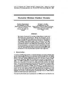
I. I NTRODUCTION It has been observed that atmospheric neutrons can produce single-event upsets (SEU’s) in digital flight control hardware [8], [9], [11], [12]. SEU’s are soft faults, which are usually transient and nondestructive to the hardware. If a bit error were not to be detected and corrected, it could cause system errors and reduce closed-loop performance. Different error recovery mechanisms have been considered for restoring the controller back to its nominal state. One experimental approach is NASA Langley Research Center’s Recoverable Computer System (RCS). Developed by Honeywell, Inc., the system implements its error recovery using dual-lockstep processors together with new fault-tolerant architectures and communication subsystems [5], [6]. It employs a variation of rollback recovery [10], [13] via the following steps: checkpointing, fault-tolerant comparison, rollback, and retry. During a checkpoint, the state of each microprocessor module is stored. When an upset is detected, rollback of both microprocessor modules to a previous checkpoint takes place, and then the system is allowed to proceed with normal execution. But once the execution of the normal control program is interrupted, the execution of a different control law takes place, one that has significantly different dynamics and is on a time scale that can alter the overall closed-loop dynamics of the flight control system. Therefore, the two control modes for this system are the nominal mode and the recovery mode. A conceptual diagram of the RCS in a closed-loop configuration is shown in Fig. 1. In [4], a general Markov jump-linear model was developed for predicting output tracking error caused by neutroninduced upsets. In this paper, the main goal is to fully develop the specific Markov jump-linear model which will be validated in future experiments using both simulated and c 0-7803-8281-1/04/$20.00 °2004 IEEE
r(k)
Dryden Shaping Filter
yg(k) +
+
up(k)
_+
yp(k)
Aircraft Dynamics
D/A
A/D
Recoverable Computer System
1
Nominal Controller
1
2
Recovery Controller
2
yc(k)
θ(k) Recovery Logic ν(k) Upset Generator
Fig. 1. A conceptual closed-loop flight control system with a recoverable flight control computer.
real neutron environments. An overview of the tracking error analysis is also provided, and a preview of the planned experiments is given. The mathematical notation used throughout this paper is largely consistent with [2], [4]. The symbol Z+ denotes the set of all non-negative integers. Rn is the n-dimensional real vector space, and M(Rn ) is the normed linear space of all n× n real matrices. The subset of all symmetric positive semidefinite matrices is M(Rn )+ . Hn = {V = (V1 , . . . , VN ) : Vi ∈ M(Rn )} will be used to denote the space of all N tuples of n × n real matrices. If every Vi of a given V in Hn is positive definite or positive semi-definite, this is indicated, respectively, by V > 0 and V ≥ 0. Hn+ denotes the set {V ∈ Hn : V ≥ 0}. Given U, V ∈ Hn , the inner product on Hn is defined by
408
hU, V i =
N X i=1
¡ ¢ tr UiT Vi ,
w (k )
and kV k2 = hV, V i is the induced norm squared of V . (k · k will also be used for representing the standard norm on Rn .) B(Hn ) is the space of all bounded linear operators on Hn under the induced operator norm
Dryden Shaping Filter
y g (k ) Kg
r (k )
+
Bp
kL(V )k kLk = sup , V 6=0 kV k
+ +
y p (k )
+−+
+ ++
Cp
Ap
where L ∈ B(Hn ). rσ (L) is used to denote the spectral radius of L, specifically, rσ (L) = kLk.
Recovery System
II. M ODELING R ECOVERABLE D IGITAL F LIGHT C ONTROL S YSTEMS
Bp
The mathematical model proposed for a recoverable digital flight control system in closed-loop has three main subsystems: the aircraft dynamics, a set of Dryden wind gust shaping filters and a rollback interference model. The specific model structure is shown in Fig. 2. Each subsystem is described in more detail below. The Aircraft Dynamics: The aircraft under consideration is a Boeing 737 in straight and level flight at a cruising altitude of 34,000 feet and speed of 0.78 Mach. The aircraft’s discretized state space model is given by xp (k + 1) = Ap xp (k) + Bp up (k) y p (k) = Cp xp (k), where the input up (k) is a vector of seven control signals: engine thrust, stabilator position, elevator deflection, right spoiler deflection, aileron deflection, rudder deflection and left spoiler deflection. xp (k) is the plant’s state vector; it contains states defined in either the aircraft body reference frame or the earth inertial reference frame. y p (k) is the output vector of the aircraft model, which contains a subset of the system states, the track angle and the calibrated airspeed. The controller is modeled under the given flight conditions by a linear output feedback control law with state space description (Ac , Bc , Cc , Dc ). Letting A˜p := Ap − Bp Dc Cp and r ≡ 0, the nominal closed-loop system is · ¸ A˜p −Bp Cc Acl = Bc Cp Ac · ¸ (1) £ ¤ I Bcl = , Ccl = Cp 0 . 0 The Dryden Wind Gust Model: As in [7], the winds and gusts are modeled by white noise, w(k), passed through Dryden shaping filters to produce random processes having the spectral densities: Lu 1 πV0 1 + (Lu ω/V0 )2 Lv 1 + 3(Lv ω/V0 )2 Svg (ω) = σv2 2πV0 [1 + (Lv ω/V0 )2 ]2
Sug (ω) = σu2
2 Swg (ω) = σw
z-1
Controller Dynamics
Upset Generator
Fig. 2.
The complete closed-loop plant structure.
where the subscripts u, v and w represent, respectively, the forward, side, and down components in the aircraft body frame, and ug , vg and wg represent corresponding winds and gusts velocity components. ω is the angular frequency; σ is the root mean square gust magnitude (ft/sec); L is the length scale for gust velocity (ft); V0 is the magnitude of the apparent wind velocity from the motion of the aircraft relative to the air mass (ft/sec). If γ ∈ {u, v, w}, δ ∈ {v, w} and V0 1 βγ = , αγ = √ βγ Lγ 3 dγ = exp(−βγ T ) · ¸ 1 1 1− (1 − dγ ) aγ = βγ T βγ 1 bγ = −aγ + (1 − dγ ) βγ Ã √ ! 1 − 1/ 3 1 (1 − dδ ) iδ = √ + βδ T 3 αδ (1 − dδ ), jδ = −iδ + βδ where T is the sample period, then the corresponding discrete-time transfer functions for the shaping filters can be expressed as r Yug (z) 2 au + bu z −1 = σu βu · Wu (z) T 1 − du z −1 r Yvg (z) 3 av + bv z −1 iv + jv z −1 = σv βv · · Wv (z) T 1 − dv z −1 1 − dv z −1 r Ywg (z) 3 aw + bw z −1 iw + jw z −1 · . = σw βw · Ww (z) T 1 − dw z −1 1 − dw z −1 Their discrete-time state space representations are given by
2
xg (k + 1) = Ag xg (k) + Bg w(k) y g (k) = Cg xg (k) + Dg w(k).
Lw 1 + 3(Lw ω/V0 ) , 2πV0 [1 + (Lw ω/V0 )2 ]2
409
(2a) (2b)
with Ag = diag(Aug , Avg , Awg ), Bg = diag(Bug , Bvg , Bwg ), Cg = diag(Cug , Cvg , Cwg ) and Dg = diag(Dug , Dvg , Dwg ), where for forward winds and gusts: £ ¤ £ ¤ Aug = du , Bug = 1 h q i Cug = σu T2 βu (bu + au du ) i h q Dug = σu T2 βu au ,
where ¤T £ T T ˆ¯ T ˆ¯ T , x ˜(k) := xT rq (k) p (k) xc (k) xg (k) x r1 (k) · · · x
and
A˜1
and for side and down winds and gusts: · ¸ ¸ · 1 2dδ −d2δ , Bδg = Aδg = 0 1 0 T q σδ T3 βδ (bδ iδ + aδ jδ + 2aδ dδ iδ ) q Cδg = σδ T3 βδ (bδ jδ − aδ d2δ iδ ) i h q Dδg = σδ T3 βδ aδ iδ .
A˜2
For the regulator problem, where the reference input signal r(k) ≡ 0, the Dryden wind gust model is integrated with the closed-loop aircraft dynamic model as shown in Fig. 3 using an input matrix Kg . w (k )
( Ag , Bg , Cg , Dg )
y g (k )
Kg
( Acl , Bcl , Ccl )
˜ B C˜
y p (k )
Fig. 3. The integrated Dryden wind gust model and the closed-loop system.
According to equations (1) and (2), the modified closed-loop system with w(k) as the input is A˜p −Bp Cc Kg Cg A˜cl = Bc Cp Ac 0 0 0 Ag Kg Dg £ ¤ ˜cl = 0 , C˜cl = Cp 0 0 . B Bg The Rollback Interference Model: In [14] (Lemma 3.2.1) a rollback interference model is given for an autonomous system. Some modifications are introduced here for the wind gust disturbances. In Fig. 1, let ν(k) denote the state of the upset process and θ(k) the state of the recovery process, which is assumed to be an aperiodic, homogeneous Markov chain with transition probability matrix Π. When θ(k) = 1, the nominal control system is engaged, and when θ(k) = 2, a recovery process is active. Let xc (k) be the state of the controller. Suppose the last checkpoint is q sample periods ˆ¯ r1 (k), . . . , x ˆ ago; and x ¯ rq (k) are q auxiliary vectors, then the rollback interference can be integrated into the model as shown below: ˜ x ˜(k + 1) = A˜θ(k) x ˜(k) + Bw(k) y p (k) = C˜ x ˜(k),
A˜p −Bp Cc Kg Cg 0 · · · Bc Cp Ac 0 0 ··· 0 0 A 0 ··· g I 0 0 ··· = 0 0 0 0 I¯ · · · .. .. .. .. . . . . . . . 0 0 0 0 ··· when θ(k) = 1, A˜p 0 Kg Cg −Bp Cc · · · 0 0 0 0 0 ··· 0 0 0 Ag 0 ··· 0 0 I ··· 0 =0 0 .. . .. .. .. .. . . .. . . . 0 0 0 0 · · · I¯ 0 0 0 0 ··· 0 when θ(k) = 2, ¤T £ = (Kg Dg )T 0 BgT 0 · · · 0 £ ¤ = Cp 0 · · · 0 .
0 0 0 0 0 .. . I¯
0 0 0 0 0 .. . 0
0 I¯ 0 0 .. . 0 I¯
Here I¯ is a modified identity matrix with diagonal entries set to zero if the corresponding states are not stored during the checkpointing. When I¯ 6= I, the recovery scheme is called partial state rollback. On the current RCS, only the elevator and aileron commands are implemented with rollback capability. Therefore, only the control states associated with those commands are rollback enabled. III. O UTPUT T RACKING E RROR M ODEL AND P ERFORMANCE M EASURES When a neutron encounter produces a detectable SEU in the flight control hardware, the RCS will rollback the state of the controller to its stored value at the previous checkpoint. During this recovery, the current control output values are frozen until the checkpointed values can be reloaded and made available. This gives rise to output tracking error, which can be described with the following state space model: · ¸ · ¸· ¸ · ¸ ˜ A˜θ(k) 0 x ˜(k + 1) x ˜(k) B = + ˜ w(k) ˜ x ˜n (k + 1) x ˜ (k) B 0 A1 n · ¸ · ¸ x ˜(0) x ˜0 = x ˜n (0) x ˜n,0 · ¸ £ ¤ x ˜(k) ˜ ˜ . y e (k) = C −C x ˜n (k)
Here x ˜(k) and x ˜n (k) are the state vectors of the switched and nominal closed-loop systems, respectively; w(k) is the white noise process used by the wind gust model; and y e (k) is the closed-loop output tracking error. Let
410
£ T ¤T ˜ ˜ xe (k) = x ˜ (k) x ˜T n (k) , Ae,1 = diag(A1 , A1 ), Ae,2 = £ T ¤T £ ¤ T ˜ ˜ diag(A˜2 , A˜1 ), Ge = B and Ce = C˜ −C˜ , then B the error system xe (k + 1) = Ae,θ(k) xe (k) + Ge w(k) xe (0) = xe,0 , θ(0) = θ 0 y e (k) = Ce xe (k)
(a) if w = 0, and for any k ∈ Z+ x0 and θ(k) are independent, then the mean output energy is ( "∞ # ) X T k ¯ J0 = E x0 Lθ0 (C) x0
(3a)
k=0
= tr(X0 Q0 ), ª ©P∞ ª © k ¯ where X0 := E x0 xT 0 , Q0 := E k=0 Lθ 0 (C) , and Li denotes the composition of L i times ¯ := C). ¯ (L0 (C)
(3b)
can be characterized by the behavior of the switching signal θ(k). It is always assumed that this jump-linear system is stable in the following sense.
(b) if for any k ∈ Z+ x0 , w(k) and θ(k) are independent, then the mean output power is ( Ã "k−1 # !) X T i ¯ G Jw = lim E tr G Lθ(k−i) (C)
Definition 1. [3] System (3a)owith w(k) = 0 is mean-square n 2 stable (MSS) if E kxe (k)k → 0 as k → ∞ for any initial condition xe,0 and any initial distribution for θ 0 . It is shown in [4] that if system (3a) is MSS, and if there are no winds and gusts, then the error signal y e (k) has finite energy. If winds and gusts are present, i.e., w(k) 6= 0, then y e (k) has finite power. The proposed output tracking error performance measure J is therefore (∞ ) X 2 : w=0 ky e (k)k J0 := E J= k=0 o n J := lim E ky (k)k2 : w 6= 0. w
k→∞
e
Calculating J0 and Jw requires some general Markov jumplinear system theory described in the next section. IV. C ALCULATING P ERFORMANCE M EASURES Consider the general Markov jump-linear model given below over a probability space (Ω, F, Pr) x(k + 1) = Aθ(k) x(k) + Gw(k) x(0) = x0 , θ(0) = θ 0 y(k) = Cθ(k) x(k),
(4a) (4b)
where {θ(k); k = 0, 1, 2, . . . } is an aperiodic Markov chain with states {1, 2, . . . , N } and transition probability matrix Π = [πij ]; x0 is a second-order random variable; and {w(k); k = 0, 1, 2, . . . } is a stationary zero mean white noise process with covariance matrix Im and inden pendent of ¡θ(k) and x0 . Let A 1 , . . . , AN ) ∈ H ¢ = (An+ T T ¯ and C = C1 C1 , . . . , CN CN ∈ H . For any S = (S1 , . . . , SN ) ∈ Hn , define an operator L ∈ B(Hn ) by L(S) = (L1 (S), . . . , LN (S)), where N X Li (S) = AT πij Sj Ai . i
k→∞
Theorem 1. [4] For a MSS system (4), where θ(k) is aperiodic and ergodic, the following identities hold:
T
= tr E G
"
= tr(Gw Qw ),
∞ X
k=0
# )!
¯ Lkθs (C)
G
T where θ s is the unique stationary ©P ª vector, Gw := GG ∞ k ¯ and Qw := E k=0 Lθ s (C) .
When system (4) is MSS, J0 and Jw can be calculated numerically P as follows. It is clear that Q = ∞ ¯ is the unique solution to (Q1 , Q2 , . . . , QN ) = k=0 Lk (C) the adjoint coupled Lyapunov equation Q − L(Q) = C¯ (the observability Gramian in [2]). This adjoint coupled Lyapunov equation can be solved using the matrix representation of L ¢ ¡ T T T A2 := diag AT 1 ⊗ A1 , . . . , AN ⊗ AN · (Π ⊗ In2 ) ,
where ⊗ denotes the ¤ (see [1], [2] for £ Kronecker product details). Let Qi = qi1 qi2 . . . qin , where qij ∈ Rn for i = 1, 2, . . . , N and j = 1, 2, . . . , n. If vec(Qi ) := ¤ £ T T T T . . . qin qi1 qi2 is the column stack of Qi and £ T ¤T ϕ(Q) := vec (Q1 ) vecT (Q2 ) . . . vecT (QN ) ∈ N n2 then the adjoint coupled Lyapunov equation can be R ¯ written as the matrix equation ϕ(Q) − A2 · ϕ(Q) ³ ´ = ϕ(C), −1 −1 ¯ . Therefore, and hence Q = ϕ (IN n2 − A2 ) · ϕ(C) the output error measures can be written in terms of (∞ ) N X X k ¯ Q0 = E (Qi · Pr{θ 0 = i}) L (C) = θ0
i=1
k=0
and Qw = E
j=1
The system is MSS if and only if rσ (L) < 1. (See [2] for additional details.) The key expressions for computing the performance measures J0 and Jw are given in the following theorem.
i=0
à (
(
∞ X
k=0
)
¯ Lkθs (C)
=
N X i=1
(Qi · Pr{θ s = i}) ,
where Pr{θ s = i} is determined by solving the eigenequation Pr{θ s = 1} Pr{θ s = 1} .. .. T . =Π · . .
411
Pr{θ s = N }
Pr{θ s = N }
V. RCS E XPERIMENT D ESCRIPTION The model validation will be done in two phases: first, data will be collected from a series of experiments conducted at the NASA Langley Research Center’s SAFETI Laboratory. The RCS flight control system will be connected in closedloop with a Boeing 737 flight simulation system running on a separate host computer. The input reference signals will be set to zero to maintain straight and level flight at a cruising altitude of 34,000 feet. A data acquisition system will be maintained on a third computer system. It will collect flight data during the simulation. Neutron interactions will be simulated by manually triggering rollback recovery according to pre-determined Markovian interference sample functions. Data will be collected for 100 sample flights of thirty minutes each. On this prototype system a maximum of 50 rollbacks are permitted before the system automatically shuts down. The aircraft’s state variables will be compared against a nominal flight, i.e., one with no rollback recoveries. The tracking error statistics will then be computed for the cases of no wind and light wind (σγ = 1 ft/sec). In general, high wind conditions can excite nonlinear modes in the aircraft dynamics, which are not modeled in the present jump-linear framework. Second, a set of experiments is planned at the Los Alamos Neutron Science Center (LANSCE) in Los Alamos, New Mexico to provide data from a real neutron environment. A conceptual diagram of the testbed for the LANSCE experiments is shown in Fig. 4. A beam of free neutrons is directed through a flux sensor at the device under test, in this case the RCS. The energy spectrum of the neutron source has a very similar shape to that produced by atmospheric neutrons. The method of data collection is similar to that done in the NASA Langley SAFETI Laboratory experiments. The outcome of these validation experiments will appear in a future publication. Beam Source
Flux Sensor
Flight Control Computer
ACKNOWLEDGEMENTS This research was supported by the NASA Langley Research Center under contracts NCC-1-392 and NCC-103026, and by the National Science Foundation under grant CCR-0209094.
Barrier
.. .. .. .. .. .. .. .. .. .. .. .. .. .. .. .. .. .. .. ...................
Data Acquisition Host Computer
Fig. 4.
Flight Simulation Host Computer
The testbed for the LANSCE experiments [4].
412
R EFERENCES [1] O. L. V. Costa and M. D. Fragoso, ‘Stability Results for Discrete-Time Linear Systems with Markovian Jumping Parameters,’ Journal of Mathematical Analysis and Applications, vol. 179, 1993, pp. 154–178. [2] O. L. V. Costa and R. P. Marques, ‘Mixed H2 /H∞ -Control of Discrete-Time Markovian Jump Linear Systems,’ IEEE Trans. Automatic Control, vol. AC-43, no. 1, 1998, pp. 95–100. [3] O. L. V. Costa and R. P. Marques, ‘Robust H2 -Control for Discrete-Time Markovian Jump Linear Systems,’ International Journal of Control, vol. 73, no. 1, 2000, pp. 11–21. [4] W. S. Gray, H. Zhang and O. R. Gonz´alez, ‘Closed-Loop Performance Measures for Flight Controllers Subject to NeutronInduced Upsets,’ Proc. 42nd IEEE Conference on Decision and Control, Maui, Hawaii, USA, 2003, pp. 2465–2470. [5] R. Hess, ‘Computing Platform Architectures for Robust Operation in the Presence of Lightning and Other Electromagnetic Threats,’ Proc. 16th Digital Avionics Systems Conference, Philadelphia, Pennsylvania, 1997, pp. 4.3–9–16. [6] R. Hess, ‘Options for Aircraft Function Preservation in the Presence of Lightning,’ Proc. 1999 International Conference on Lightning and Static Electricity, Toulouse, France, Paper No. 106, 1999. [7] E. F. Hogge, ‘B-737 Linear Autoland Simulink Model,’ NASA Internal Report, May, 2002, pp. 38–80. [8] G. C. Messenger and M. S. Ash, The Effects of Radiation on Electronic Systems, 2nd ed., Van Nostrand Reinhard, New York, 1992. [9] G. C. Messenger and M. S. Ash, Single Event Phenomena, Chapman & Hall, New York, 1997. [10] R. Narasimhan, D. J. Rosenkrantz, and S. S. Ravi, ‘Early Comparison and Decision Strategies for Datapaths that Recover from Transient Faults,’ IEEE Trans. Circuits & Systems I-Fundamental Theory & Applications, vol. 44, no. 5, 1997, pp. 435–438. [11] E. Normand and T. J. Baker, ‘Altitude and Latitude Variations in Avionics SEU and Atmospheric Neutron Flux,’ IEEE Trans. Nuclear Science, vol. 40, no. 6, 1993, pp. 1484–1490. [12] E. Normand, ‘Single-Event Effects in Avionics,’ IEEE Trans. Nuclear Science, vol. 43, no. 2, 1996, pp. 461–474. [13] A. Ranganathan and S. Upadhyaya, ‘Performance Evaluation of Rollback-Recovery Techniques in Computer Programs,’ IEEE Trans. Reliability, vol. 42, 1993, pp. 220–226. [14] A. Tejada, ‘Analysis of Error Recovery Effects on Digital Flight Control Systems,’ M.S. Thesis, Department of Electrical and Computer Engineering, Old Dominion University, 2002.