Published in IEEE Transactions on VLSI Systems, 2013. DOI:10.1109/TVLSI.2013.2278289
MASTER: A Multicore Cache Energy Saving Technique using Dynamic Cache Reconfiguration Sparsh Mittal, Student Member, IEEE, Yanan Cao, and Zhao Zhang, Member, IEEE
Abstract—With increasing number of on-chip cores and CMOS scaling, the size of last level caches (LLCs) is on rise and hence, managing their leakage energy consumption has become vital for continuing to scale performance. In multicore systems, the locality of memory access stream is significantly reduced due to multiplexing of access streams from different running programs and hence, leakage energy saving techniques such as decay cache, which rely on memory access locality, do not save large amount of energy. The techniques based on way level allocation provide very coarse granularity and the techniques based on offline profiling become infeasible to use for large number of cores. We present MASTER, a multicore cache energy saving technique using dynamic cache reconfiguration. MASTER uses online profiling to predict energy consumption of running programs at multiple LLC sizes. Using these estimates, suitable cache quotas are allocated to different programs using cache coloring scheme and the unused LLC space is turned off to save energy. Even for 4 core systems, the implementation overhead of MASTER is only 0.8% of L2 size. We evaluate MASTER using out-of-order simulations with multiprogrammed workloads from SPEC2006 and compare it with conventional cache leakage energy saving techniques. The results show that MASTER gives highest saving in energy and does not harm performance or cause unfairness. For 2 and 4-core simulations, the average savings in memory subsystem (which includes LLC and main memory) energy over shared baseline LLC are 15% and 11%, respectively. Also, the average values of weighted speedup and fair speedup are close to one (≥0.98). Index Terms—Multicore processors, cache leakage energy saving, cache reconfiguration, dynamic profiling, green computing, cache partitioning.
I. I NTRODUCTION Recent trends in chip architectures and CMOS scaling have made the design of computer systems increasingly energyconstrained [1]. With increasing number of cores integrated on a single chip [2], [3], the pressure on the memory system is rising and to mitigate this pressure, modern processors are using large sized LLCs; for example, both Intel’s 4-core Xeon E3-1290 processor and AMD’s 4-core Opteron 3320E processor use 8MB LLC [4], [5]. Further, with each CMOS technology generation, leakage energy consumption has been increasing exponentially [6]–[8] and hence, large LLCs contribute significantly to the total processor power consumption [9]. The increased levels of power consumption necessitate expensive cooling solutions which significantly increase the overall system cost and design complexity and also restrict further performance scaling. Further, in several scenarios, the The authors are with the Department of Electrical and Computer Engineering, Iowa State University, Ames, IA, 50014 USA e-mail:
[email protected],{yanan,zzhang}@iastate.edu. This work is supported in part by the NSF under grants CNS-0834476 and CNS-1117604.
actual number of programs running on a multicore processor are much less than the number of cores and thus, a large amount of cache leakage energy is wasted. For these reasons, managing the power consumption of LLCs has become an important research issue in modern processor design. The conventional cache energy saving techniques face significant challenges when used for managing energy consumption of shared LLCs in multicore processors. For example, the techniques such as decay cache [10] exploit the locality property of memory access streams and place the ‘dead’ cache lines into low leakage mode for saving leakage energy. Since single-core workloads typically exhibit high locality, these techniques are effective in saving energy in singlecore systems. However, in the case of multicore systems with shared LLCs, the independent access streams from multiple applications are interleaved and thus, the actual memory access stream exhibits reduced locality. The techniques which allocate and turn-off cache at way granularity [11]–[15] can only provide few coarse grain partitions (at most, as many as the number of ways) while drastically reducing the associativity for each program. Finally, some techniques use offline profiling or compiler analysis of running applications for saving energy [11], [16]–[20]; however, due to the large number of possible program combinations in multicore environment, use of offline profiling becomes increasingly difficult. In this paper, we present MASTER, a multicore cache energy saving technique using dynamic cache reconfiguration. MASTER works by periodically allocating suitable amount of LLC space to each running application and turning off unused LLC space to save cache energy. MASTER uses a simple “cache coloring” scheme and thus, allocates cache at the granularity of a single cache color (Section III). For profiling the behavior of running programs under different LLC cache sizes, MASTER uses a small microarchitectural component, called “reconfigurable cache emulator” (RCE). RCE is a tag-only (data-less) component and is designed using the set sampling method. RCE does not lie on critical access path and because of its small size, its access latency is easily hidden. With this lightweight hardware support, MASTER energy saving algorithm periodically predicts the memory subsystem energy of running programs for a small number of color values. Using these estimates, MASTER selects a configuration with minimum estimated energy and turns off the unused cache colors for saving leakage energy (Section IV). For hardware implementation of cache block switching (i.e. turning-off), MASTER uses the well-known gated Vdd technique [21] (Section V). We evaluate MASTER using out-of-order simulations with
c ⃝2013 IEEE. Personal use of this material is permitted. Permission from IEEE must be1obtained for all other uses, in any current or future media, including reprinting/republishing this material for advertising or promotional purposes, creating new collective works, for resale or redistribution to servers or lists, or reuse of any copyrighted component of this work in other works.
2
Sniper [22], a state-of-art x86-64 simulator and multiprogrammed workloads from SPEC2006 suite (Section VI). We compare it to decay cache technique (DCT) [10] and way adaptable cache technique (WAC) [13]. The results show that MASTER saves highest amount of memory subsystem energy (Section VII). For example, over a shared baseline LLC, for 2 and 4-core systems (with one program on each core), the average savings in memory subsystem energy by using MASTER are 14.7% and 11.2%, respectively. Using WAC (which, on average, performs better than DCT), these values are only 10.2% and 6.5% respectively. Further, the average values of weighted speedup and fair speedup using MASTER remain very close to one (≥0.98) and absolute increase in DRAM APKI (accesses per kilo instructions) remains less than 0.5. Thus, MASTER does not harm performance or cause unfairness. Additional simulation results show that MASTER works well for a wide variety of system parameters. The remainder of the paper is organized as follows. Section II presents a background on cache energy saving techniques and also discusses related work. Section III discusses the system architecture and components of MASTER and Section IV presents the energy saving algorithm. The implementation details and experimental methodology are discussed in Section V and VI, respectively. Section VII presents the experimental results on MASTER and other techniques. It also evaluates the sensitivity of MASTER for different system parameters. Finally, Section VIII provides the conclusion and the future work. II. BACKGROUND AND R ELATED W ORK The energy saving approach of MASTER has two broad steps. In the first step, the LLC quotas to be allocated to different cores (and to be turned off) are decided and then these quotas are actually enforced. In the second step, a leakage control mechanism is used to turn off the cache blocks for saving energy. In literature, different schemes have been proposed which allocate or turnoff cache space at the granularity of cache colors [23]–[25], cache ways [11]–[14], [26], [27], cache sets [17], [21], [28], both sets and ways (hybrid) [29], [30] and cache blocks [10], [31]. MASTER determines cache quotas with the goal of optimizing energy efficiency and enforces it using a cache coloring scheme. The circuit-level leakage control mechanisms are divided into two types, namely state-destroying [21] and statepreserving [31], [32]. The state-destroying mechanisms do not retain data in low-leakage mode and hence, access to such a block incurs a cache miss; however, these mechanisms typically reduce more leakage power than the statepreserving mechanisms [21], [31], [33]. The state-preserving mechanisms retain data in low leakage mode but generally require two supply voltages for each block and also make the cache more susceptible to noise [31], [34]. Hence, MASTER employs state-destroying leakage control by using gated Vdd mechanism [21]. Recently, researchers have proposed techniques for saving both leakage and dynamic energy in caches. With no leakage optimization applied, LLCs spend a large fraction of their
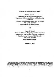
energy in the form of leakage energy [35], [36]. Hence, we aim at saving cache leakage energy. Some energy saving techniques work by statically allocating or turning off a part of cache and do not allow dynamic runtime reconfiguration [11], [14], [16]. However, since the behavior of applications varies significantly over their execution length, dynamic cache reconfiguration is important for realizing large energy savings. Karthik et al. [12] propose a technique which uses marginal utility values to allocate suitable number of ways to each core. Further, it uses way-alignment approach to force the data of a core to be in the given way(s) for all the sets of the cache. Using this information, on a cache access only the designated way(s) can be accessed which leads to saving in dynamic energy. Also, the unused ways can be turned off to save leakage energy. Other researchers perform way-partitioning in dynamic [15] or static manner [14]. However, as mentioned before, way-partitioning provides only limited granularity. For example, since at least a single way must be allocated to each core, a typical 8-way associative cache cannot be partitioned among 8 cores and even for a 4 core system, it provides only few options for partitioning and way turn-off. Thus, use of these techniques requires caches of large associativity, which have higher access time and dynamic energy. This limits the usefulness of these techniques. An important difference between MASTER and most existing cache energy saving techniques (e.g. [10], [12], [13], [21], [27], [30]) is that MASTER works to directly optimize energy value, while existing techniques do not directly work to optimize cache energy, rather they aim to keep the increase in cache misses resulting from cache turnoff small, which leads to energy saving. Due to this feature, MASTER can optimize for system (or subsystem) energy, instead of only cache energy. Several cache energy saving techniques proposed in literature (e.g. [12], [15], [16], [18], [36]–[38]) have been evaluated by considering their effect on LLC energy only. We model both LLC energy and main memory energy for a more comprehensive evaluation. III. S YSTEM A RCHITECTURE AND D ESIGN MASTER works on the idea that different programs and even different execution phases of a single program have different working set sizes and hence, by allocating just suitable amount of cache to the programs, the rest of the cache can be turned off, with little impact on performance. Figure 1 shows the flow diagram of MASTER. In the following, we explain each of the components of MASTER in more detail. Notations and Assumptions: We use N to denote the number of cores and n or k to show core indices. The interval index is shown using i. The maximum number of cache colors is shown as M . System page size is taken as 4KB and all caches use a block size of 64B. The terms “active” and “turned off” are used to refer to the cache space (either cache block, color or way), which is in normal leakage and low leakage mode, respectively. The term “color value” denotes the number of colors given to each core and “configuration” denotes the colors given to all the N cores, e.g. a 2-core configuration {37, 65} specifies that color values of core 0 and core 1 are
3
L2 Access (Address and Core ID)
Address
Physical Page No. Page Number in Region
Core ID
Region ID
Page Offset Set # Inside Color
Offset
L2 Tag
Counters RCE
Energy Saving Algorithm
Remap/control
Counters
Software/OS
Processor
Fig. 1. Flow diagram of MASTER approach (Assuming M = 128, page size = 4KB, cache block size = 64). Color indices for cache access are computed using mapping tables for each core. To partition the cache, the energy saving algorithm remaps the mapping table. RCE is accessed in parallel to L2.
37 and 65, respectively. We assume that the LLC is an L2 cache; and the discussion can be extended to the case where LLC is an L3 cache. The baseline cache is taken as shared LLC, as done in several recent works [12], [23], [39]. A. Cache Coloring Scheme For selective cache allocation, MASTER uses cache coloring scheme [23], [24], [40], which is as follows. First, we logically divide the cache into M disjoint groups, called cache colors, where total number of colors (M ) is given by M=
L2CacheSize PageSize × L2Associativity
(1)
Further, we logically divide the physical pages into disjoint groups, called memory regions. For each core, the number of memory regions is M . Thus, a memory region denotes the group of physical pages of a core that share log2 (M ) least significant bits of the physical page number. A cache color is given to one or more memory regions of a single core and thus, all physical pages in those memory regions are mapped to the same cache color. For each core, we use a small mapping table of M entries, each log2 (M )-bit wide, which stores the mapping of memory regions to cache colors. At any instance, if the number of colors allocated to core n is cn , then the mapping table of core n stores the mapping of its M regions to cn colors. Thus, cache quotas are enforced by mapping all the memory regions of a core to only its allocated cache colors. Further, when quota allocation is such that the sum of allocated colors is less than M , the remaining colors become unused which can be turned off for saving leakage energy. Using mapping tables, computation of cache index (set) is done as follows (Figure 1). For any L2 access from core n, its memory region ID is computed by simple bit-masking. Using memory region ID, the cache color is read from the mapping table of core n and the set number inside the color is decided by the most significant bits of the page offset. While previous set level allocation techniques [21], [29], [30] reconfigure the cache only to power-of-two set-counts,
MASTER allocates and turns off cache at the granularity of a single cache color and hence it reconfigures the cache to nonpower-of-two set-counts also; for example, at an instance, it may keep only 37 colors as active. From Eq. 1, we find that an 8-way 4MB cache has 128 colors. Thus, with merely an 8way cache, MASTER provides much finer granularity of cache allocation than the previous set, way or hybrid (set and way) level allocation techniques [12], [21], [26], [29], [30]. Also, MASTER turns off both tag and data arrays of the unused colors, in contrast with some techniques which only turn off data array and always keep the tag fields active [41], [42]. Lin et al. [23] present a coloring scheme which does not require hardware support and can control mapping of every OS page individually. In contrast, MASTER uses lightweight hardware support and can control the address mapping only at the level of a memory region which contains multiple pages. However, the limitation of their scheme is that repartitioning incurs significant overhead since the data of whole virtual page needs to be copied from an old physical page to a new physical page. Since MASTER uses mapping table to add a layer of mapping between physical pages and cache colors, it avoids the need of page migration and also keeps the reconfiguration overhead small. Further, as shown in Section V, the overhead of mapping tables is extremely small. B. Reconfigurable Cache Emulator (RCE) For estimating program energy consumption under different color values, the number of cache misses under them needs to be estimated. A challenge in obtaining profiling data for color (or set) level allocation is that, unlike for way level allocation [26], a single auxiliary tag structure cannot provide profiling information for different cache sizes (Note that since MASTER does not dynamically reconfigure associativity or block size, change in cache size simply means change in the set-count.). Hence, to estimate performance at multiple cache sizes, these cache sizes need to be individually profiled. However, since caches have a large number of colors, profiling for each possible color value would be extremely costly.
4
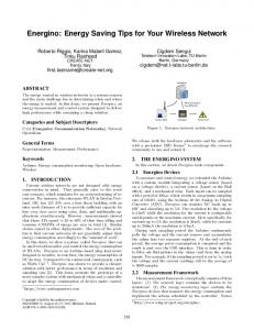
To address this issue, MASTER uses RCE, which profiles only a few selected cache sizes (called profiling points) and uses piecewise linear interpolation to estimate miss rates for other cache sizes. In this paper, we use seven profiling points, each denoted by (2j−1 X)/64, where j = {1, 2, 3, 4, 5, 6, 7} and X denotes the L2 cache size (or equivalently number of L2 colors). Corresponding to each profiling point, MASTER uses an auxiliary tag structure, called profiling unit for each core. To keep the overhead of profiling units small, MASTER leverages “set sampling” approach [43]. The ratio of set-counts of L2 and that of a profiling unit is called sampling ratio (Rs ). L2 Access (Address and Core ID)
Address Mappers
Finite State Control
64X/64
0 1 Queue RS
32X/64 16X/64 8X/64 4X/64 2X/64 X/64
MUX
Sampling Filter
in our experiments (see Section VI-A and VI-C) and have found values of FRCE in the same range. Taking into account both RCE and mapping tables, we conservatively assume the maximum storage overhead of MASTER as 0.8% of L2 which occurs for 4 core systems. Clearly, the overhead of MASTER is small. The RCE overhead can be further reduced by half by taking the sampling ratio as 128, although it leads to slight reduction in the energy saving achieved (Section VII-C). Note that RCE works in parallel to L2 and does not lie at the critical access path and does not store or communicate data. A miss in RCE does not generate any request for other caches. Each address mapper is simple, since it only performs bit-matching and additions. For each sampled address from core n, the RCE storage of core n is accessed seven times. However, due to the use of queue, large value of Rs and dataless operation of RCE, no congestion occurs, even in the case of bursty L2 accesses. RCE design is flexible and can be easily extended to also profile for sizes such as X/128 and X/256, although this also increases the number of profiling units consulted in each RCE access.
N-1 Storage for N cores
Fig. 2. RCE design (Assuming 64 or more colors). For every cache access, only 1/Rs accesses pass filter and then all the seven profiling units of originating core are accessed using set-decoding and MUX.
The RCE works as follows (Figure 2). Any L2 access address, originating from a core (say n) is sampled by a sampling filter which removes block offset bits and uses bitmatching to decide whether the address passes the filter. An address which passes the filter is further passed through a queue. Then, each address mapper (shown as A1 to A7) computes cache tag and set using traditional set-decoding (and not cache coloring). Also, to map the address to suitable region in the storage, it adds an offset corresponding to its profiling unit and core index of the address. Afterwards, using a small multiplexer (MUX), the incoming addresses are sequentially fed to the tag-only storage region for emulating cache access. In summary, the profiling units have a tag storage and setdecoding mechanism and thus, each profiling unit emulates a specific cache size. By using all the profiling units, the variation in miss-rate with cache size can be estimated for each core. We now compute the size of RCE. Let Q denote the number of sets in L2 and S denote the number of sets in RCE for all the cores. Further, let G and L denote the size of tag and block size in bits, respectively and FRCE denote the total size of RCE as a percentage of L2 size. Thus, we get ∑7 ( j=1 2j−1 ) × N × Q 127N Q 2N Q S= = ≤ (2) 64 × Rs 64Rs Rs RCESize N × 127G FRCE = × 100 = × 100 (3) L2CacheSize 64Rs (L + G) In our experiments Rs = 64, G = 28, L = 64×8 and hence, for 2 and 4-core systems, we get FRCE as 0.3% and 0.6%, respectively. To cross-check, we have computed areas of RCE and L2 using CACTI [44] for the cache sizes chosen
C. Marginal Color Utility (MCU) In each interval, MASTER computes marginal color utility values which are used by the energy saving algorithm (Section IV). The notion of marginal gain has been previously used [26], [45]. In context of MASTER which uses cache coloring and RCE, we define MCU for the non-uniformly spaced profiling points for which miss-rate information is available using RCE and use the unit as a single cache color. For each core n, at any color value cn , the value of MCU, MCUn (cn ), is defined as the reduction in cache misses per extra unit cache color. We assume that between two profiling points, the number of misses vary linearly with cache size (piecewise linear approximation) and hence, MCU remains constant between those profiling points. Let Cp1 = X/64, Cp2 = 2X/64 . . . Cp7 = 64X/64 denote the seven profiling points as mentioned above. Then, if the number of L2 misses of core n at these profiling points is denoted by Missn (Cpj ) (where j = {1, 2, 3, 4, 5, 6, 7} and n = {0, 1, . . . , N − 1}), then for Cp1 ≤ cn ≤ Cp7 , MCUn (cn ) is defined as follows. Missn (Cpj ) − Missn (Cpj+1 ) Cpj ≤ cn < Cpj+1 j+1 j C − C p p MCUn (cn ) = Missn (Cp6 ) − Missn (Cp7 ) cn = Cp7 Cp7 − Cp6 (4) IV. E NERGY S AVING A LGORITHM (ESA) We now discuss the energy saving algorithm of MASTER which runs after a fixed interval length (e.g. 5M cycles) and can be a kernel module. Since the future values are unknown, the algorithm works by using the observed values from interval i to make predictions about interval i + 1. Without loss of generality, we assume single-threaded workloads and hence, use the words ‘core’ and ‘application’ interchangeably. We discuss generic values of parameters, along with their specific values for 2 and 4 cores systems. Let cn (i) denote the color
5
value of core n in interval i. The algorithm has the following steps. 1. Selection of color values: For each core, ESA intelligently selects Tmax (= 4 in our experiments) possible color values. Let ConfigSpace[n] be the set of these color values. The selection of color values is done using following criteria. A. To avoid application starvation, ESA allocates at least Min (=M/64 in our experiments) colors to each core. Such color values are termed as ‘valid’ color values. B. To keep the reconfiguration overhead low and avoid oscillations, ‘valid’ color values are searched only in close vicinity of cn (i) (i.e. cn (i) ± 10). C. Based on intuitive observation, if an application has low MCU, then reducing its cache allocation does not significantly increase its miss rate but provides opportunities of turning off the cache or allocating the cache to other cores. Thus, for applications with low MCU, the color values having smaller number of active colors are likely to be energy efficient and vice-versa. To quantify smallness or largeness of MCU, we use four application-independent thresholds, viz. λq (q = 1, 2, 3, 4), which are heuristically taken as 50, 200, 300 and 1000, respectively in our experiments. By comparing MCUn (cn ) to the threshold values, its range is decided and thus, the color values for core n are chosen. For example, if for core 3, MCU3 (c3 ) equals 250 (λ2 < MCU3 (c3 ) ≤ λ3 ), then ConfigSpace[3] equals {c3 − 1, c3 , c3 + 4, c3 + 6}, assuming all the color values are all valid (if not, the invalid color value is replaced by a valid one). 2. Configuration Space Reduction: For each of the Tmax color values in ConfigSpace[n], the contribution of core n in memory subsystem energy is estimated (see next paragraph). Then, out of these Tmax color values, T color values with least energy are selected for each core and the other color values are discarded. In our experiments, for N = 2, T = Tmax = 4 and for N = 4, T = 2. Note that for N = 2, T = Tmax and hence, this step is not required for the 2-core system. For N = 4, the energy computations are done for a maximum of N Tmax (=16) color values. We model the total energy E as the sum of energy spent in L2 cache (EL2 ), DRAM (EDRAM ) and the energy cost of algorithm execution (EAlgo ). Thus, E = EL2 + EDRAM + EAlgo
(5)
The detailed computations of EL2 etc. are shown in Section VI-C. We use Equation 5 to estimate the contribution of core n in memory subsystem energy for any color value cn , as follows. Since we are only interested in comparing energy for different color values, and not in their actual magnitudes, we ignore the quantities which are common. L2 dynamic energy depends on number of L2 misses and hits at cn , which are estimated using RCE. For a fixed interval length, time consumed is fixed and hence L2 leakage energy only depends on the active fraction of cache, which is equal to cn /M . DRAM dynamic energy depends on DRAM accesses and hence on L2 misses and writebacks. L2 miss estimates are already available. The number of writebacks are assumed to be same for different color values and hence are ignored. This assumption has only a small affect on estimation accuracy
since most applications bring only small number of dirty blocks in L2, not all of which are expected to be evicted in an interval. 3. Selection of N -core configurations: ESA now generates all possible combinations of N -core configuration, using color values from ConfigSpace[n] of all N cores. Out of these, the configurations with sum of active colors greater than M are discarded. 4. Selection of Final Configuration: Depending on the number of remaining configurations, ESA chooses one of the following steps. A. For the remaining configurations, memory subsystem energy is computed (procedure is same as above, except that now it is for N -core configuration and not just for a single core) and the configuration with minimum energy (call it Cmin ) is selected. Memory subsystem energy for current configuration (call it Cnow ) is also computed. If compared to Cnow , Cmin improves energy by at least 0.3% (chosen arbitrarily), Cmin is chosen for the next interval. Otherwise Cnow is taken for i + 1. B. If no configuration remains, Cnow is taken for i + 1. Here Cij shows jth color value for ith core Step1: Select 4 color values for each core Core
Answer
Step 2: Choose 2 energy efficient color values for each core
0
1
2
3
0
1
2
3
C01 C02 C03 C04
C11 C12 C13 C14
C21 C22 C23 C24
C31 C32 C33 C34
C01 C02 C03 C04
C11 C12 C13 C14
C21 C22 C23 C24
C31 C32 C33 C34
1. C01 C11 C22 C33 2. C01 C11 C22 C34 3. C01 C11 C23 C33 ……….. 16. C03 C13 C23 C34 Step 4: Find most energy efficient configuration
1. C01 C11 C22 C33 2. C01 C11 C22 C34 3. C01 C11 C23 C33 ……….. 16. C03 C13 C23 C34 Step 3: Form 4-core configurations
Fig. 3. Illustration of ESA for N = 4. Except for step 2, similar steps apply for N = 2.
For N = 4, these steps are graphically shown in Figure 3. The maximum number of configurations tested is T N + 1. From above, for both N = 2 and 4, the maximum number of configurations tested is always 17. Discussion: In each execution, ESA only examines a maximum of 16 color values and 17 configurations and hence, the overhead of ESA is small. Also, by using MCU values, ESA makes an intelligent prediction about the configurations which are likely to be most energy efficient. The threshold values chosen are application-independent and hence, do not require per-application tuning. As can be seen from the results (Section VII), our chosen values provide significant energy saving for almost all the workloads and a designer can further exercise trade-off between algorithm efficiency and energy saving obtained by choosing a proper value of Tmax , T and the interval length. Algorithm implementation is further discussed in Sections V and VI-B.
6
V. I MPLEMENTATION Cache block switching: For hardware implementation of cache block switching, MASTER uses gated Vdd scheme [21] which has also been used by several researchers [10], [12], [32], [33]. We use a specific implementation of gated Vdd ( NMOS gated Vdd , dual Vt, wide, with charge pump) which reduces leakage energy by 97% and results in 5% area penalty and 8% access latency penalty [21]. We account for these overheads below and in Section VI. Also note that mechanism to turn off a subset of LLC is already provided by the existing commercial processor chips [3], [46]. Effect on cache access time: With MASTER, block switching only happens at the end of an interval and RCE is accessed in parallel to L2 and hence, these activities do not happen on the critical path. Further, MASTER does not require use of caches of large associativity which have higher access time and dynamic energy. Hence, the impact of MASTER on cache access time comes due to access to mapping table and use of gated Vdd scheme. To see the maximum overhead of mapping tables, which in our experiments occurs for 4core system, we take the example of an 8-way, 8MB cache which has 256 colors. Thus, the total size of mapping tables of all cores is 8192 bits (= 4 × 256 × 8), merely 0.012% of L2 cache size (tag+data) and hence their access latency and energy consumption are negligible. Since mapping tables are changed only during cache reconfigurations, access to them can be folded into the address decode tree of the cache’s tag and data arrays. The gated Vdd scheme increases access latency by 8%. With baseline L2 latency as 12 cycles, we take the L2 latency with MASTER as 13 cycles (Section VI-A). Counters: MASTER uses counters for RCE (recording number of misses in each profiling point, MCUs etc.) and ESA (recording color values, configurations and their energy values etc.). Since the energy consumption of counters is much smaller than that of memory subsystem (LLC+DRAM) and several processors already have counters for operating system or performance measurement [10], we ignore the overhead of counters in energy calculations. Also note that MASTER does not require tracking the application-ownership of each cache block or altering the replacement policy (unlike [12], [26]). MASTER works independent of the replacement policy used (see Section VII-C) and hence, does not require using a specific replacement policy such as true-LRU which has higher implementation overhead than the “approximate LRU” schemes [47]. Further, MASTER does not require using perblock counters to monitor cache access intensity (unlike [10], [31]) or tables for offline profiling (unlike [14], [18]). Handling reconfigurations: L2 reconfigurations are handled in the following manner. When a color (say cn ) is ‘allocated’ to a core (say n), one or more regions of core n, which were mapped to some other color, are now mapped to the color cn and the blocks of remapped region in the old color are flushed (i.e. dirty data is written back to memory and other blocks are discarded). Conversely, when a color (say ck ) is ‘taken away’ from a core (say k), the blocks of core k in cache color ck are flushed and then, the regions of core k, which were mapped to ck , are now mapped to some other
color(s) of core k. Change in mapping is accomplished by using the mapping table (Section III-A). The time taken in running the algorithm is accounted in Section VI-B. The existing set level allocation schemes turn off cache at power-of-two set counts [29], [30] and hence, the change in set-decoding on reconfigurations necessitates flushing a large number of blocks. In contrast, with MASTER, cache reconfiguration changes the set locations of only those addresses which were (or are going to be) stored in the transferred colors. Thus, MASTER incurs smaller reconfiguration overhead than the previous schemes. Compared to the lazy reconfiguration approach [23], [28], the reconfiguration scheme of MASTER is simpler, requires less state storage and always maintains consistency. Reconfigurations happen only at most once every interval which is of the order of a few million cycles and hence, the overhead of reconfigurations is amortized over the interval length. Indeed, our results (Section VII) show that MASTER keeps increase in number of DRAM accesses small (less than 0.5 per kilo instructions) and this confirms that the reconfiguration overhead of MASTER is small. VI. E XPERIMENTAL M ETHODOLOGY A. Simulation Environment and Workload We conduct out-of-order simulations using interval core model in Sniper x86-64 multi-core simulator [22], which has been verified against real hardware. Each core has a 128-entry ROB, dispatch width of 4 micro-operations and frequency of 2.8GHz. L1I and L1D caches are private to each core and L2 cache is shared among the cores. Both L1I and L1D are 32KB, 4-way, LRU caches with 2 cycle latency. The L2 cache is unified 8-way, LRU and its size for 2 and 4core simulations are 4MB and 8MB respectively. This range of cache sizes are typical in commercial processors [4], [5], [48]. L2 latency for baseline simulations is 12 cycles and for MASTER, DCT and WAC (Section VI-B), it is 13 cycles since they all use gated Vdd scheme. Main memory latency is 196 cycles and memory queue contention is also modeled. For 2core configuration, peak memory bandwidth is 12.8 GB/s and for 4-core configuration, it is 25.6 GB/s. Interval length is 5M cycles. We use all 29 SPEC CPU2006 benchmarks with ref inputs. For workload construction, the benchmarks are classified following a methodology similar to Jiang et al. [16]. Based on the change in L2 miss-rate from a 4MB L2 to 64KB L2, benchmarks were sorted and then classified into two groups namely high-gain (H) and low-gain (L) such that each group has nearly half the benchmarks. This is shown in Table I. TABLE I B ENCHMARK CLASSIFICATION High(H)
Low(L)
astar(As), bzip2(Bz), calculix(Ca), dealII(Dl) gcc(Gc), gemsFDTD(Gm), gromacs(Gr), lbm(Lb), leslie3d(Ls), omnetpp(Om), soplex(So) sphinx(Sp), xalancbmk(Xa), zeusmp(Ze) bwaves(Bw), cactusADM(Cd), gamess(Ga), gobmk(Gk), h264ref(H2), hmmer(Hm), libquantum(Lq) mcf(Mc), milc(Mi), namd(Nd), perlbench(Pe) povray(Po), sjeng(Sj), tonto(To), wrf(Wr)
7
TABLE II W ORKLOADS FOR 2 AND 4 CORE SYSTEMS . HxLy SHOWS THAT THE WORKLOAD HAS x HIGH - GAIN AND y LOW- GAIN BENCHMARKS
H2L0 H1L1 H0L2 H4L0 H3L1 H2L2 H1L3 H0L4
2-core workloads T1(AsDl), T2(GcLs), T3(GmGr), T4(LbXa), T5(BzLs) T6(SoMi), T7(ZeCd), T8(CaTo), T9(SpMc), T10(OmLq) T11(SjWr), T12(BwNd), T13(HmGa), T14(GkH2), T15(PePo) 4-core workloads F1(SoGrZeLb), F2(OmSpGmGc), F3(BzGrLsGm) F4(LsZeOmLq), F5(GmCaLbCd), F6(CaAsXaMc) F7(BzDlGaMc), F8(SpGcLqHm), F9(XaLbMiGk) F10(SoNdMiBw), F11(DlCdGkGa), F12(AsPeToWr) F13(BwPoNdH2), F14(HmSjPoH2), F15(SjToWrPe)
Using this classification, multiprogrammed workloads are randomly constructed with different combinations of H and L benchmarks (Table II). T1 to T15 are two-core workloads and F1 to F15 are four-core workloads. Except for completing the left-over groups, each SPEC benchmark is used exactly once for 2-core workloads and exactly twice for 4-core workloads. The evaluation metrics used are shown in Table III. Here TABLE III E VALUATION M ETRICS U SED Percent Energy Saved Weighted Speedup [23] Fair Speedup [23]
((E(base) − E(scheme)) × 100)/E(base) Σn (IPCn (scheme)/IPCn (base))/N N/Σn (IPCn (base)/IPCn (scheme))
scheme refers to either MASTER, DCT or WAC and E shows the total energy, as defined in Section IV. Each benchmark was fast-forwarded for 10B instructions and the workloads were simulated till each core completes at least 500M instructions. A core that has finished its 500M instructions is allowed to run, but for computation of fair speedup and weighted speedup, its IPC is recorded only for 500M instructions, following previous works [12], [26], [39]. Energy values are recorded for entire execution, following [14], since this enables us to account for the effect of increased execution time on energy consumption. Across the workload, average value of fair speedup and weighted speedups are calculated as geometric means (Gmean) of perworkload improvements. For all the other quantities reported in the paper, average values are calculated as arithmetic means (Amean). To gain insights, we also present results on the following two quantities. The first is ActiveRatio, which is defined as the active cache area fraction, averaged over the entire simulation length [10]. For any technique, ActiveRatio shows its aggressiveness of cache turnoff and thus, gives an estimate of effective cache capacity used. The second is absolute increase in DRAM accesses per kilo instructions (APKI) due to use of a scheme, over baseline. This is calculated as (APKI(scheme)−APKI(base)). Through this, we measure the increase in both L2 misses and writebacks due to cache turnoff and reconfigurations. APKI is very useful since it enables us to measure off-chip traffic or in other words, the effect of cache management on main memory. We have also checked the increase in L2 misses and writebacks individually and have found similar trends as in DRAM access increase. We report absolute difference values and not the relative difference, following previous works [29], [49].
B. Comparison with Other Techniques Decay Cache Technique (DCT): DCT [10] works by turning off a block which has not been accessed for the duration of ‘decay interval’ (DI). Following [10], [33], DCT is implemented using gated Vdd and hierarchical counters; both tag and data arrays are decayed and latency of waking up decayed block is assumed to be overlapped with memory latency. For computing DI, we used competitive algorithms theory [10]. As shown in Section VI-C, a 4MB, 8-way L2 cache has a leakage power consumption of 1.39 Watts and dynamic access energy of DRAM is 70nJ. Hence, for 2.8GHz frequency, the leakage energy per cycle per block for L2 is 1.39 /(2.8×65536) nJ. Thus, the ratio of DRAM access energy and L2 leakage energy per cycle per block is 9.2M cycles. Hence, we take the value of decay interval as 9.2M cycles. Way Adaptable Cache (WAC) Technique: WAC [13] saves energy by keeping only few MRU (most recently used) ways in each set of the cache active. WAC computes the ratio (call it Z) of hits to the least recently used active way and the MRU way. It also uses two threshold values, viz. T1 and T2 . When Z < T1 , it is assumed that most cache accesses of the program hit near MRU ways and hence, if more than two ways are active, a single cache way is turned off. Conversely, when Z > T2 , cache hits are distributed over different ways and hence, a single cache way is turned on [13]. WAC checks for possible reconfiguration after every K cache hits. Following [13], we take T1 = 0.005, T2 = 0.02, K = 100, 000 and use gated Vdd for hardware implementation. We have chosen these techniques, since, like MASTER, they both use state-destroying leakage control. Also, DCT turns off cache at block granularity (fine granularity), while WAC turns off cache at way granularity (coarse granularity) and hence, these techniques help us evaluate MASTER against different energy saving mechanisms. Time overhead of running MASTER, DCT and WAC energy saving algorithms is taken as 500, 300 and 20 cycles, respectively; and when cache is reconfigured, all the three techniques incur additional 600 cycles average overhead. The reasoning for choosing these values of algorithm overhead is as follows. The decision mechanism of WAC only requires division for computation of Z and comparison with T1 and T2 ; and thus, its execution overhead is quite small (20 cycles). DCT uses hierarchical counters where global counter sends ticks for all the cacheblock counters [10]. Thus, the decision mechanism of DCT includes comparison of all the 2-bit block counters with zero and assuming that some parallelism and/or pipelining is used to reduce the total overhead, we conservatively chose the overhead as 300 cycles. The decision mechanism of MASTER includes selecting candidate color values, estimating core energy values, configuration space reduction, estimating total energy values and choice of best configuration. MASTER does not scan per-block counters and computes energy for a small number (viz. 16+17) of configurations. Thus, assuming that by using some parallelism and/or pipelining the overhead can be reduced, we conservatively chose the overhead as 500 cycles. We believe that these overhead values are reasonable, reflecting the relative overhead of different techniques and also
8
comparing well with the typical overhead values assumed in the literature, for example [50]. We have also experimented with the statically, equallypartitioned cache. On average, for 2 and 4 core configurations, this scheme leads to nearly 2% and 4% loss in energy compared to the shared baseline, respectively. Hence, on taking this scheme as the baseline, the savings of MASTER will be even larger. For sake of brevity, we omit these results. C. Energy Modeling As stated in Section IV, we model the energy spent in L2 cache, DRAM and the energy cost of algorithm execution. Dyn Leak We use the following notations. Pxyz and Exyz show the leakage energy per second and the dynamic energy per access, respectively, in a component xyz (e.g. L2, DRAM and RCE). Dyn Gf and Df (= 1 − Gf ) show the fraction of EL2 , which is spent in accessing data array and tag array, respectively. DEL2 and LEL2 show the total dynamic and leakage energy consumed in L2. Etran shows the total energy consumed in block transitions and Eχ shows the energy consumed in a single block transition. Tran shows the number of block transitions. In an interval, FA , W , ML2 and HL2 show the active fraction of cache, number of active ways, L2 misses and L2 hits respectively. Assoc shows L2 associativity. Time denotes the time length of an interval in seconds. ADRAM and ARCE show the number of DRAM accesses and RCE accesses, respectively. Υ shows the area overhead of gated Vdd cell as a fraction of area of the normal cell. Poff shows the leakage power consumption at low leakage as a fraction of normal Leak leakage power, PL2 . For computing L2 leakage energy, we account for the consumption of both active and low-leakage portion of the cache and also assume that the increase in area due to the use of gated Vdd leads to an increase in leakage energy in the same proportion. The L2 dynamic energy in accessing data array is assumed to scale with the number of active ways [11], [15], [51] and an L2 miss is assumed to consume twice the dynamic energy as that of an L2 hit [29], [32]. Thus, we get EL2 = LEL2 + DEL2
+ Υ) × (FA + (1 − FA )Poff ) × Time (7) Df × W Dyn = EL2 × (2ML2 + HL2 ) × (Gf + ) (8) Assoc Dyn Leak = PDRAM × Time + EDRAM × ADRAM (9)
LEL2 = DEL2 EDRAM
(6)
Leak PL2 (1
Dyn Leak EAlgo = Etran + ERCE × ARCE + PRCE × Time
Etran = Eχ × Tran
(10) (11)
Note that for baseline experiments, EAlgo = 0, Υ = 0 and FA = 1 and Poff value is not required. RCE energy cost is only incurred in MASTER. For MASTER, DCT and baseline, W = Assoc, since these techniques do not turn off the cache ways. Based on CACTI, we take Gf = 0.03 and Df = 0.97 for all cache sizes. For MASTER, DCT and WAC, FA represents the fraction of active colors, active blocks and active ways, respectively. For gated Vdd scheme, Poff = 0.03 and Υ = 0.05 [21], which applies to MASTER, DCT and Dyn Leak WAC. The values of PL2 and EL2 are obtained using CACTI
[44] assuming 8-bank, 8-way at 32nm and they are shown in Dyn Leak Table IV. PDRAM and EDRAM are taken as 0.18 Watt and 70 nJ, respectively [29], [52] and Eχ is taken as 2 pJ [29]. The energy values of RCE are computed using CACTI [44] and Eq. 2. Since RCE only stores tags, we take the energy values of tag arrays only. These values act as upper bounds of RCE energy consumption, since without data arrays, dirty bits etc., RCE can be implemented even more efficiently. The Dyn Leak values of PRCE and ERCE are shown in Table IV, assuming 8B block size and a single bank structure. Noting that for every 64 L2 accesses, RCE is accessed only 7 times, we conclude that the energy consumption of RCE is a very small fraction of L2 energy consumption. TABLE IV E NERGY VALUES FOR L2 C ACHE AND C ORRESPONDING N - CORE RCE L2 cache Cache Size 4MB 8MB
Dyn
EL2 (nJ/access) 0.289 0.438
Leak PL2 (Watt) 1.39 2.72
RCE Number of cores (N ) 2 4
Dyn
ERCE (nJ/access) 0.005 0.016
Leak PRCE (Watt) 0.006 0.023
VII. R ESULTS AND A NALYSIS A. Example of Working of MASTER To get insights into working of MASTER, we first show examples of cache partitioning and reconfiguration taking place with selected workloads in Figure 4. The workloads have been selected to illustrate different types of patterns of cache allocation. For 2-core workloads, we see that for T3(gemsFDTD, gromacs), both benchmarks are in the H category (refer Table II) and hence, they compete for cache, and MASTER algorithm is able to turn-off some fraction of cache for saving energy. For T10(omnetpp, libquantum), libquantum is a streaming benchmark, while omnetpp has high cache demand and hence, the algorithm allocates most of the cache to omnetpp and turns off very small fraction of cache. For T15(perlbench, povray), both benchmarks are in the L category and hence, MASTER algorithm reduces their cache quota and turns off a large amount of cache for saving energy. Similarly, for 4-core workloads we see that for F3(bzip2, gromacs, leslie3d, gemsFDTD), all benchmarks are in the H category and hence, they compete for cache and a small fraction of cache is turned-off for saving energy. For F9(xalancbmk, lbm, milc, gobmk), the cache quota of different benchmarks settles after some time. Also, milc is a streaming benchmark and hence, its cache quota is significantly reduced since that does not harm its performance. Similarly the cache quota of lbm is reduced, while that of xalancbmk is increased from the initial quota since the performance of xalancbmk is improved from the extra cache allocation. Finally, for F15(sjeng, tonto, wrf, perlbench), all the benchmarks are in the L category and hence, MASTER algorithm turns-off a large fraction of cache for saving energy without hurting performance. Also note that different workloads take different execution time depending on the time required for finishing the slowest
9
Two core workload -- T3(gemsFDTD,gromacs)
Number of colors
128 96 64 32 gemsFDTD gromacs
0 Algorithm intervals Two core workload -- T10(omnetpp,libquantum)
Number of colors
128 96 64 32 omnetpp libquantum
0 Algorithm intervals Two core workload -- T15(perlbench,povray)
Number of colors
128 96 64 32 perlbench povray
0 Algorithm intervals
Number of colors
Four core workload -- F3(bzip2,gromacs,leslie3d,gemsFDTD) 256 224 192 160 128 96 64 32 0
bzip2 gromacs leslie3d gemsFDTD Algorithm intervals
Number of colors
Four core workload -- F9(xalancbmk,lbm,milc,gobmk) 256 224 192 160 128 96 64 32 0
xalancbmk lbm milc gobmk Algorithm intervals
Number of colors
Four core workload -- F15(sjeng,tonto,wrf,perlbench) 256 224 192 160 128 96 64 32 0
sjeng tonto wrf perlbench Algorithm intervals
Fig. 4.
Examples of working of MASTER for selected 2-core and 4-core workloads. Unallocated colors (empty portion of the graphs) are turned-off.
application. Hence, the number of algorithm intervals is also different for different workloads. B. Comparison of Energy Saving Techniques Figures 5 and 6 show the results on energy saving, weighted speedup and ActiveRatio. Other quantities are summarized in Table V and figures for them are omitted for brevity. For 2 and 4-core system, energy savings of MASTER (DCT and WAC) are 14.72 (9.43 and 10.18) and 11.16 (4.92 and 6.55), respectively.
TABLE V R ESULTS ON FAIR SPEEDUP, ACTIVE RATIO
MASTER DCT WAC
Fair speedup N=2 N=4 0.99 0.99 0.98 0.98 0.99 0.99
AND
DRAM APKI
INCREASE
APKI Increase N=2 N=4 -0.51 0.17 0.55 0.53 0.16 0.23
Clearly, MASTER provides largest improvement in energy efficiency, weighted speedup and fair speedup. With increasing
10
70 60 50 40 30 20 10 0 -10
% Energy saved (2-core system)
T1
T2
1.06 1.04 1.02 1 0.98 0.96 0.94 0.92 0.9
T3
T4
T5
T6
T7
T8
T9
T10
Weighted Speedup (2-core system)
T1
T2
T3
T4
T5
T11
T12
T6
T7
T8
T9
T10
T11
T13
WAC
T14
DCT
MASTER
T12
MASTER
ActiveRatio (2-core system)
1
DCT
MASTER
T13
T15
Avg
WAC
T14
DCT
T15
Avg
WAC
0.8 0.6 0.4 0.2 0 T1
Fig. 5.
T2
T3
T4
T5
T6
T7
T8
T9
T10
T11
T12
T13
T14
T15
Avg
Results on percentage energy saved, weighted speedup and ActiveRatio for 2 core system. MASTER provides largest energy savings.
N , intra-application interference increases and locality of memory access stream decreases and hence, the energy saving achieved by application-insensitive techniques such as DCT and WAC decreases. This fact is confirmed by the results on ActiveRatio which show that the average ActiveRatio values with DCT and WAC are more than 0.69. In contrast, MASTER turns off a large fraction of cache while keeping DRAM access increase low and this translates into large energy savings. With MASTER, fair speedup values are close to one. Thus, by allocating cache in proportion to the cache demand of individual applications, MASTER maintains fairness and does not affect QoS (quality of service) or cause thread starvation. Further, despite turning off and flushing a portion of L2, MASTER reduces the DRAM APKI for many workloads, such as T4, T6, T10, F9 etc. In fact, for 2-core system, on average, DRAM APKI is reduced by 0.51. This is because, by managing the cache quota of different applications and containing the thrashing applications, MASTER reduces the number of L2 misses and writebacks. DCT and WAC increase DRAM APKI more than MASTER. Looking into the essential energy saving mechanisms of different techniques, we observe that DCT considers the access intensity to cache block as a measure of its usefulness or liveliness and uses this information to turn off the cache. However, for many benchmarks and especially for streaming ones such as libquantum and milc, access intensity shows up to be a poor measure of data reuse and usefulness of a block and hence, for most workloads, DCT does not save large amount of leakage energy. With increasing N , the intra-application interference reduces the opportunity of turning off the cache even further. The advantage of DCT is that it turns off cache at block granularity and hence, achieves larger energy saving for some workloads such as T15. WAC works by using ratio of hits in MRU and LRU positions as a measure of locality present in the memory access stream and turns off cache at way granularity, while always keeping at least 2 ways active. Clearly, due to way
level allocation approach, WAC turns off cache only at coarse granularity and reduces the associativity of the cache. The advantage of WAC is that it always turns off least recently used blocks in the LRU chain which are less likely to be reused in the future. Further, by turning off ways, it also reduces the dynamic energy consumed in accessing data array of the cache. MASTER works by estimating energy consumption of a few configurations and choosing a configuration with highest energy efficiency. It takes into account the cache demands of each application and hence, can easily account for streaming or non-streaming applications. Further, MASTER enforces strict cache quotas and alleviates inter-application interference, which also helps in maintaining performance and fairness. MASTER allocates cache at color granularity and hence it does not hurt associativity. With MASTER, the contribution of EAlgo in total memory subsystem energy consumption for 2 and 4 core systems is 0.25% and 0.39%, respectively. Given the large energy saving achieved by MASTER, its small overhead is justified. A limitation of MASTER is that it allocates at least M/64 colors to each application and hence, for applications with very small working set size, it may lose the opportunity to turn off the cache further. This limitation can be easily addressed by reducing the lower limit (see Section III-B), depending on the typical working set size of the applications and acceptable RCE overhead. Based on our experiments, we have observed that M/64 color limit is reasonable since it enables significant energy savings and also avoids any possibility of performance degradation. The aggressiveness with which an energy saving technique should turn off the cache depends, not only on the application behavior, but also on other factors such as relative energy consumption of cache and other processor components. While DCT and WAC cannot directly take other components into account, their effect is implicitly seen in the choice of decay interval in DCT and K, T1 and T2 in WAC. Thus, statically choosing the optimal (or best) value(s) of the parameters in these techniques is likely to require significant efforts and the
11
50
MASTER
% Energy saved (4-core system)
40
DCT
WAC
30 20 10 0 -10 F1
F2
1.06 1.04 1.02 1 0.98 0.96 0.94 0.92 0.9 0.88
F3
F4
Weighted speedup
F1
F2
F3
F5
F6
F7
F8
F9
F10
(4-core system)
F4
F5
F6
F12
MASTER
F7
F8
F9
F10
F11
F13
F14
F15
DCT
F12
MASTER
ActiveRatio (4-core system)
1
F11
F13
Avg
WAC
F14
F15
DCT
Avg
WAC
0.8 0.6 0.4 0.2 0 F1
Fig. 6.
F2
F3
F4
F5
F6
F7
F8
F9
F10
F11
F12
F13
F14
F15
Avg
Results on percentage energy saved, weighted speedup and ActiveRatio for 4-core system. MASTER provides largest energy savings.
values may also vary for different platforms and optimization targets. In contrast, MASTER is capable of accounting and directly optimizing for system (or subsystem) energy at runtime and it can easily adjust its aggressiveness of cache turnoff depending on the trade-off between energy saving and performance loss from cache turnoff. In fact, the energy saving approach of MASTER presented here can be easily extended to optimize for overall system energy by merely including the energy model of other processor components. C. Sensitivity To Different Parameters We henceforth focus exclusively on MASTER. We study its sensitivity for different system parameters. In each case, only a single parameter is changed from the default configuration and the results are shown in Table VI. Wherever applicable, Dyn for changed parameters, the energy values such as ERCE etc. were computed as shown in Section VI-C. For sake of brevity, we omit these values. In all cases, the average fair speedup is more than 0.97 and hence, these results are also omitted. The following two parameters apply to MASTER technique. Interval length: To see the possibility of reducing reconfiguration overhead, we change the interval length to 10M cycles. As shown in Table VI, this slightly reduces energy saving and slightly improves performance, which is expected. Thus, MASTER can work at coarse interval sizes and is not very sensitive to the choice of a specific interval length. Sampling ratio (Rs ): We change Rs in RCE to 128. From Table VI, we observe a small reduction in energy saving, which is due to reduced accuracy in profiling information, although the energy savings are still large. Thus, at the cost of slightly reduced energy saving, the overhead of RCE can be further reduced. The following two parameters apply to both baseline and MASTER. Cache associativity: On changing L2 associativity (Assoc) to 16, while keeping the size same, we observe that MASTER still offers large energy savings (Table VI).
TABLE VI E NERGY SAVING , WEIGHTED SPEEDUP (WS) AND APKI I NCREASE FOR DIFFERENT PARAMETERS . D EFAULT PARAMETERS : INTERVAL LENGTH = 5M CYCLE , Rs = 64, A SSOC = 8, LRU POLICY. R ESULTS WITH DEFAULT PARAMETERS ARE ALSO SHOWN .
Default Interval=10M Rs = 128 Assoc = 16 FIFO policy PLRU policy
% Energy Saved N=2 N=4 14.7 11.2 14.0 11.6 12.9 10.3 15.8 13.9 12.9 12.8 14.3 12.0
WS N=2 N=4 0.99 0.99 1.00 1.00 0.99 0.99 0.99 0.99 0.99 1.00 0.99 0.99
APKI Increase N=2 N=4 -0.51 0.17 -0.68 -0.17 0.04 0.61 -0.51 0.23 -0.54 -0.18 -0.45 0.14
Replacement policy: We first change the replacement policy to FIFO (first-in, first-out) and then to MRU bits based pseudo-LRU (PLRU) [47]. The large values of energy savings (Table VI) show that MASTER works independent of the replacement policy used.
D. The Case When The Number Of Programs Is Less Than The Number Of Cores As discussed before, in several cases the actual number of programs running on a processor is much less than the number of cores. This is especially expected to be true for future processors which would have a large number of cores. To test the effectiveness of MASTER in such cases, we simulate 4-core configuration with 2-core workloads (shown in Section VI-A). We run one program each on the first two cores while the other two cores remain idle. The results are shown in Figure 7. Using MASTER, we observe an energy saving of 25.3%, weighted speedup of 0.96, fair speedup of 0.96 (considering only the two active cores for both weighted speedup and fair speedup), DRAM APKI increase of 1.29 and active ratio of 0.33. Clearly, since in this case, the cache size available to each core is large, MASTER aggressively reconfigures the cache to provide large energy saving.
12
80 70 60 50 40 30 20 10 0
% Energy saved (4-core system, 2-core workload)
T1
T2
1.02 1 0.98 0.96 0.94 0.92 0.9 0.88
T3
T4
T5
T6
T7
MASTER
T8
T9
T10
T11
T12
T13
T14
Weighted Speedup (4-core system, 2-core workload)
T1
T2
T3
T4
T5
T6
T7
T8
Avg
MASTER
T9
T10
T11
T12
T13
T14
T15
Avg
MASTER
ActiveRatio (4-core system, 2-core workload)
1
T15
0.8 0.6 0.4 0.2 0 T1
Fig. 7.
T2
T3
T4
T5
T6
T7
T8
T9
T10
T11
T12
T13
T14
T15
Avg
Results on percentage energy saved and weighted speedup for 4 core system with 2-core workloads
VIII. C ONCLUSION In this paper, we have presented MASTER, a cache leakage energy saving approach for multicore caches. MASTER uses coloring scheme to partition cache space at the granularity of a single cache color. By using low-overhead RCE for estimating performance and energy of running applications at multiple cache sizes, MASTER periodically reconfigures the LLC to most energy efficient configuration. Out-of-order simulations performed using SPEC06 workload have shown that MASTER is effective in saving memory subsystem energy and does not harm performance or cause unfairness. Our future work will focus on synergistically integrating MASTER with other techniques for saving energy (e.g. dynamic energy saving techniques, cache compression, etc.) and testing it for a system with a larger number of cores. R EFERENCES [1] S. Borkar and A. Chien, “The future of microprocessors,” Communications of the ACM, vol. 54, no. 5, 2011. [2] IBM, http://www-03.ibm.com/systems/power/hardware/. [3] N. Kurd et al., “Westmere: A family of 32nm IA processors,” IEEE International Solid-State Circuits Conference Digest of Technical Papers (ISSCC), pp. 96–97, 2010. [4] http://ark.intel.com/products/55452. [5] http://www.amd.com/US/PRODUCTS/SERVER/PROCESSORS/3000SERIES-PLATFORM/3300/Pages/3300-series-processors.aspx#4. [6] “International technology roadmap for semiconductors (ITRS),” www.itrs.net/Links/2011ITRS/2011Chapters/2011ExecSum.pdf, 2011. [7] S. Borkar, “Design challenges of technology scaling,” Micro, IEEE, vol. 19, no. 4, pp. 23 –29, Jul. 1999. [8] S. Rodriguez and B. Jacob, “Energy/power breakdown of pipelined nanometer caches (90nm/65nm/45nm/32nm),” ISLPED, pp. 25–30, 2006. [9] M. Monchiero, R. Canal, and A. González, “Design space exploration for multicore architectures: a power/performance/thermal view,” International Conference on Supercomputing, pp. 177–186, 2006. [10] S. Kaxiras, Z. Hu, and M. Martonosi, “Cache decay: exploiting generational behavior to reduce cache leakage power,” ISCA, pp. 240–251, 2001. [11] D. H. Albonesi, “Selective cache ways: on-demand cache resource allocation,” MICRO, pp. 248–259, 1999. [12] K. T. Sundararajan et al., “Cooperative partitioning: Energy-efficient cache partitioning for high-performance CMPs,” HPCA, pp. 1–12, 2012.
[13] A. Bardine et al., “Leveraging data promotion for low power D-NUCA caches,” 11th EUROMICRO Conference on Digital System Design Architectures, Methods and Tools, pp. 307–316, 2008. [14] W. Wang, P. Mishra, and S. Ranka, “Dynamic cache reconfiguration and partitioning for energy optimization in real-time multi-core systems,” DAC, pp. 948–953, 2011. [15] I. Kotera, K. Abe, R. Egawa, H. Takizawa, and H. Kobayashi, “Poweraware dynamic cache partitioning for CMPs,” Transactions on Highperformance Embedded Architectures and Compilers III, pp. 135–153, 2011. [16] X. Jiang et al., “ACCESS: Smart scheduling for asymmetric cache CMPs,” HPCA, pp. 527–538, 2011. [17] S.-H. Yang et al., “An integrated circuit/architecture approach to reducing leakage in deep-submicron high-performance I-caches,” HPCA, pp. 147–157, 2001. [18] R. Reddy and P. Petrov, “Cache partitioning for energy-efficient and interference-free embedded multitasking,” ACM Transactions on Embedded Computing Systems (TECS), vol. 9, no. 3, p. 16, 2010. [19] C. Zhang, F. Vahid, and W. Najjar, “A highly configurable cache architecture for embedded systems,” ISCA, pp. 136–146, 2003. [20] W. Zhang et al., “Compiler-directed instruction cache leakage optimization,” in MICRO-35, 2002, pp. 208–218. [21] M. Powell, S.-H. Yang, B. Falsafi, K. Roy, and T. Vijaykumar, “GatedVdd: a circuit technique to reduce leakage in deep-submicron cache memories,” ISLPED, pp. 90–95, 2000. [22] T. E. Carlson, W. Heirman, and L. Eeckhout, “Sniper: Exploring the level of abstraction for scalable and accurate parallel multi-core simulations,” International Conference for High Performance Computing, Networking, Storage and Analysis (SC), pp. 1–12, 2011. [23] J. Lin et al., “Gaining insights into multicore cache partitioning: Bridging the gap between simulation and real systems,” HPCA, pp. 367–378, 2008. [24] J. Lin et al., “Enabling software management for multicore caches with a lightweight hardware support,” International Conference on High Performance Computing Networking, Storage and Analysis, 2009. [25] S. Mittal, Z. Zhang, and Y. Cao, “CASHIER: A Cache Energy Saving Technique for QoS Systems,” 26th International Conference on VLSI Design and 12th International Conference on Embedded Systems (VLSID), pp. 43–48, 2013. [26] M. K. Qureshi and Y. N. Patt, “Utility-based cache partitioning: A low-overhead, high-performance, runtime mechanism to partition shared caches,” MICRO, pp. 423–432, 2006. [27] K. Kedzierski et al., “Power and performance aware reconfigurable cache for CMPs,” IFMT, 2010. [28] P. Ranganathan, S. Adve, and N. P. Jouppi, “Reconfigurable caches and their application to media processing,” ISCA, pp. 214–224, 2000. [29] S. Mittal and Z. Zhang, “EnCache: Improving cache energy efficiency using a software-controlled profiling cache,” IEEE International Conference On Electro/Information Technology, 2012.
13
[30] S. Yang, B. Falsafi, M. Powell, and T. Vijaykumar, “Exploiting choice in resizable cache design to optimize deep-submicron processor energydelay,” HPCA, pp. 151–161, 2002. [31] K. Flautner, N. Kim, S. Martin, D. Blaauw, and T. Mudge, “Drowsy caches: simple techniques for reducing leakage power,” ISCA, pp. 148– 157, 2002. [32] H. Hanson et al., “Static energy reduction techniques for microprocessor caches,” IEEE TVLSI, vol. 11, no. 3, pp. 303 –313, 2003. [33] Y. Li et al., “State-preserving vs. non-state-preserving leakage control in caches,” DATE, vol. 1, pp. 22–27, 2004. [34] J. L. Ayala et al., “Energy-aware compilation and hardware design for vliw embedded systems,” International Journal of Embedded Systems, vol. 3, no. 1, pp. 73–82, 2007. [35] H. Homayoun, A. Veidenbaum, and J. Gaudiot, “Adaptive techniques for leakage power management in L2 cache peripheral circuits,” ICCD, pp. 563–569, 2008. [36] L. Li et al., “Leakage energy management in cache hierarchies,” PACT, pp. 131 – 140, 2002. [37] S. Dropsho et al., “Integrating adaptive on-chip storage structures for reduced dynamic power,” PACT, pp. 141–152, 2002. [38] A. Udipi, N. Muralimanohar, and R. Balasubramonian, “Non-uniform power access in large caches with low-swing wires,” International Conference on High Performance Computing (HiPC), pp. 59–68, 2009. [39] D. Sanchez and C. Kozyrakis, “Vantage: scalable and efficient fine-grain cache partitioning,” ISCA, pp. 57–68, 2011. [40] R. Kessler and M. Hill, “Page placement algorithms for large realindexed caches,” ACM TOCS, vol. 10, no. 4, pp. 338–359, 1992. [41] J. Abella, A. González, X. Vera, and M. O’Boyle, “IATAC: a smart predictor to turn-off L2 cache lines,” ACM Transactions on Architecture and Code Optimization, vol. 2, no. 1, pp. 55–77, 2005. [42] H. Zhou, M. Toburen, E. Rotenberg, and T. Conte, “Adaptive mode control: A static-power-efficient cache design,” ACM Transactions on Embedded Computing Systems, vol. 2, no. 3, pp. 347–372, 2003. [43] T. Puzak, “Cache memory design,” Ph.D. dissertation, University of Massachusetts, 1985. [44] CACTI 6.5, http://www.hpl.hp.com/research/cacti/. [45] G. E. Suh, L. Rudolph, and S. Devadas, “Dynamic partitioning of shared cache memory,” J. Supercomput., vol. 28, no. 1, pp. 7–26, 2004. [46] A. Naveh et al., “Power and thermal management in the intel core duo processor,” Intel Technology Journal, vol. 10, no. 2, pp. 109–122, 2006. [47] “Performance evaluation of cache replacement policies for the SPEC CPU2000 benchmark suite,” Al-Zoubi, H. and Milenkovic, A. and Milenkovic, M., pp. 267–272, 2004.
[48] R. Kumar and G. Hinton, “A family of 45nm IA processors,” IEEE International Solid-State Circuits Conference Digest of Technical Papers (ISSCC), pp. 58–59, 2009. [49] D. K. Tam, R. Azimi, L. B. Soares, and M. Stumm, “RapidMRC: approximating L2 miss rate curves on commodity systems for online optimizations,” ASPLOS, pp. 121–132, 2009. [50] X. Ding, D. S. Nikolopoulos, S. Jiang, and X. Zhang, “Mesa: reducing cache conflicts by integrating static and run-time methods,” in IEEE ISPASS, 2006, pp. 189–198. [51] M. Powell, A. Agrawal, T. Vijaykumar, B. Falsafi, and K. Roy, “Reducing set-associative cache energy via way-prediction and selective directmapping,” MICRO, pp. 54–65, 2001. [52] H. Zheng et al., “Decoupled DIMM: building high-bandwidth memory system using low-speed dram devices,” ISCA, pp. 255–266, 2009.
Sparsh Mittal received his B.Tech in Electronics and Communications Engineering from the IIT, Roorkee, India. He was the graduating topper of his batch and his major project was awarded institute silver medal. At present, he is pursuing his PhD in Electrical and Computer Engineering at Iowa State University, USA. He has been awarded scholarship and fellowship from IIT Roorkee and ISU. His research interests include memory system power efficiency, cache architectures in multicore systems and real-time systems. Yanan Cao received his B.S. in Electronics Engineering from the Fudan University, Shanghai, China. At present, he is pursuing his PhD in Electrical and Computer Engineering at Iowa State University, USA. He has been awarded scholarship and fellowship from both Fudan University and ISU. His research interests include design of cache and memory architectures.
Zhao Zhang received the BS and MS degrees in computer science from Huazhong University of Science of Technology, China, in 1991 and 1994, respectively, and the PhD degree in computer science from the College of William and Mary in 2002. He is an associate professor of computer engineering at Iowa State University. His research interests include computer architecture, parallel and distributed systems, and architectural support for system security.