Palette: A Cache Leakage Energy Saving Technique For Green Computing Sparsh MITTAL a,1 , and Zhao ZHANG a of Electrical and Computer Engineering, Iowa State University, Iowa, USA
a Department
Abstract. With each CMOS technology generation, leakage energy has been increasing at an exponential rate. Since modern processors employ large last level caches (LLCs), their leakage energy consumption has become an important concern in modern chip design. To address this issue, several techniques have been proposed. However, most of these techniques require offline profiling and hence, cannot be used in real-life systems which run trillions of instructions of arbitrary applications. In this paper, we propose Palette, a technique for saving cache leakage energy using cache coloring. Palette uses a small hardware component called reconfigurable cache emulator, to estimate performance and energy consumption of multiple cache configurations and then selects the configuration with least energy consumption. Simulations performed with SPEC2006 benchmarks show the superiority of Palette over existing cache energy saving technique. With a 2MB baseline cache, the average saving in memory sub-system energy and EDP (energy delay product) are 31.7% and 29.5%, respectively. Keywords. Leakage Energy Saving, Dynamic Profiling, Cache coloring, Reconfigurable Cache Emulator, Dynamic Cache Reconfiguration
1. Introduction Large power consumption of high-performance processors has been identified as the most severe obstacle in scaling their performance towards Exascale computing [1, 2]. It has been estimated that an exascale machine using the technology used in today’s supercomputers will consume several giga watts of power [3]! For this reason, power management techniques are extremely essential for enabling high-performance computing (HPC) to transition towards Exascale processing. Further, in recent years, the cache energy consumption of computing systems has also increased. There are several trends motivating this shift. Several state-of-the-art applications executed on modern processors require high computation resources [4–7], and to improve their performance, designers use large sized last level caches (LLCs) as the last line of defense against memory wall; for example, Intel’s Enterprise Xeon processor uses 30 MB LLC [8]. Further, with each CMOS technology generation, the leakage energy consumption has been dramatically increasing [9] and hence, the energy consump1 Corresponding Author: Sparsh Mittal, Department of Electrical and Computer Engineering, Iowa State University, Iowa, USA, 50014 ; E-mail:
[email protected] The work is supported in part by the US National Science Foundation (NSF) under the grant CNS-1117604.
tion of LLCs is also on rise. Since caches consume a large fraction of chip area, they contribute significantly to the processor power consumption. To manage increased energy dissipation levels, expensive cooling solutions (e.g. liquid cooling) are required, which also increase the design complexity. Thus, saving cache energy is crucial for continuing to scale performance and also realize the goals of green computing. Recently several techniques have been proposed for saving energy in caches. However, these techniques have several limitations. Several existing techniques require offline profiling [10, 11], however, due to the large difference between profiled and actual runs, and the overhead of offline profiling, these techniques are not suitable for realworld systems. Several existing techniques turn off cache blocks based on number of accesses to them in a given time period. However, for many programs, the number of accesses does not accurately reflect the cache reuse characteristic and benefit obtained from cache allocation. Hence, these techniques fail to save large amount of energy for such programs. In this paper, we propose Palette, a cache coloring based leakage energy saving technique using dynamic cache reconfiguration. Palette uses a small hardware component called “reconfigurable cache emulator” (RCE) which provides miss rate estimates for multiple cache sizes. Using this, along with the memory stall cycle estimation model, Palette estimates program execution time under multiple possible cache configurations. Then, for these configurations, memory sub-system energy is estimated. Further, using the energy saving algorithm, the cache is reconfigured to the most energy efficient configuration and the unused colors are turned off for saving leakage energy. For switching (i.e. turning on/off) cache blocks, Palette uses the gated Vdd scheme [12]. Palette has several salient features which address the limitations of previous techniques. Palette uses dynamic profiling and not offline profiling and hence, it can be easily used in production systems. Palette optimizes for energy directly, unlike existing techniques, which control other parameters (e.g. miss rate, number of dead blocks [13, 14]) to save energy in an indirect manner. By virtue of this feature, Palette can optimize for system (or subsystem e.g. memory sub-system) energy, and not merely cache energy and hence, it can easily detect the case when saving cache energy may increase the energy consumption of other components of the processor. Palette allocates cache based on how much a program will benefit from extra cache. Hence, it saves large amount of energy for most programs, including streaming programs. We perform microarchitectural simulations using out-of-order core model from Sniper simulator [15] and benchmark programs from SPEC2006 suite. Further, we compare Palette with a well-known cache leakage saving technique, called “decay cache technique” (DCT) [14]. The experimental results show that Palette is effective in saving energy and outperforms the conventional energy saving technique. Using Palette, the average saving in memory sub-system energy and EDP (energy delay product), compared to a 2MB baseline cache are 31.7% and 29.5%, respectively. In contrast, using DCT, the saving in energy and EDP are only 21.3% and 10.9%, respectively. The rest of the paper is organized as follows. Section 2 discusses the related work and Section 3 explains the design of Palette. Section 4 presents the energy saving algorithm and Section 5 discusses the hardware implementation of Palette. Section 6 discusses the simulation environment, workload, and energy model. Section 7 presents results on energy saving. Finally, Section 8 concludes the work.
2. Background and Related Work Recent advances in high performance computing have made several applications computationally amenable [16–18]. High performance computing platforms provision large cache resources to bridge the gap between the speed of processor and main memory. This however, also brings the issue of managing power consumption of caches. In this paper, we address this issue using dynamic cache reconfiguration approach. In literature, several techniques have been proposed for saving cache energy. A few techniques aim to save cache dynamic energy [19]. However, a large fraction on energy dissipated in LLCs is in the form of leakage energy [20], and hence, cache dynamic energy saving techniques have only limited utility in saving energy in LLCs. Palette aims at saving leakage energy of the cache and hence, it is useful for saving energy in LLCs. Several techniques use static cache reconfiguration [21, 22], however, programs show a large variation in their cache demands over different phases and hence, dynamic cache reconfiguration is important to achieve large energy savings. Some leakage energy saving techniques always keep the tag fields turned on and turn off only the selected regions of the data-array, e.g. [23]. In contrast, Palette turns off both tag and data arrays of the inactive region. Different energy saving techniques turn off cache at different granularity, such as cache ways [22], cache sets [13], hybrid (sets and ways) [10, 24] and cache blocks [14, 23]. Selective ways approach incurs low reconfiguration overhead; however, its cache allocation granularity is limited by the number of cache ways. Selective sets and hybrid approaches generally incur higher reconfiguration overhead, since on a change in the setcounts, the set-decoding scheme changes and whole cache needs to flushed. In contrast, the cache coloring scheme used in Palette incurs smaller reconfiguration overhead than selective sets or hybrid approaches, since on a change in the number of active colors, the set-locations of only the affected cache colors are changed. Some existing cache energy saving techniques (e.g. [25]) work for QoS systems where tasks have deadlines. Hence, these techniques aims to meet deadline, even at the cost of losing the opportunity of saving energy. In contrast, Palette aims to save energy while keeping performance loss small; thus Palette is suitable for systems which do not have task deadlines and for such systems, Palette can provide even more energy saving than the techniques for QoS systems. As for circuit-level leakage control mechanism, both state-destroying [12] and statepreserving [26, 27] techniques have been used. The state-preserving techniques typically save less power in low-leakage mode than the state-destroying techniques and also increase the noise susceptibility of the memory cell [28]. For this reason, Palette uses state-destroying leakage control using gated Vdd mechanism [12].
3. Palette Design and Architecture It is well-known that there exists large intra-application and inter-application variations in the cache requirements of different applications. Since several applications executed on the modern processors are performance-critical [29–31] and hence, designers use an LLC size which meets the requirements of such performance-critical applications. However, this leads to wastage of energy in the form of cache leakage energy. Palette works
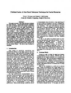
on the intuition, that in any interval, a suitable amount of cache can be allocated to a program, while the rest of the cache can be turned-off for saving leakage energy. Figure 1 shows the overall flow of Palette. In this section, we discuss each of the components of Palette in detail. We assume that the LLC is the L2 cache, and the discussion can be easily extended to the case when the LLC is an L3 cache.
Energy Saving Algorithm
Remap
Counters
Software Hardware
L2 Access Physical Address
RCE Tag
L2 Tag
63 Region Number
Mapping Table
2 1
Set Number Inside Color
Set
Block Offset
Offset
0 L2 Cache Storage (64 colors) L2 Cache
Figure 1. Palette Flow Diagram
3.1. Coloring Scheme To selectively reconfigure the cache, Palette uses cache coloring technique [32, 33]. Let B denote the L2 block size; H denote the physical page size and P denote the number of sets in L2. In modern memory management, physical memory is divided into physical pages (see Figure 2). Thus, the least significant log2 H bits of physical address are referred to as page offset and the remaining bits are referred to physical page number. Further, the least significant log2 B bits are used as block offset and the next log2 P bits are used for finding the set index of the address in the cache. Thus, there are several common bits between the physical page number and the cache set index, which are referred to as the cache color. The number of these bits is given by log2 N, where N shows the total number of cache colors. Thus, we have log2 N + log2 H = log2 P + log2 B =⇒ N =
P×B H
(1) (2)
Further, we logically group these pages into N memory regions. A memory region refers to a group of physical pages that share the log2 (N) least significant bits of the page number. Cache coloring works by controlling the mapping from memory regions to
Physical Page Number
Page Offset Set Index
Block offset
Memory Region ID
Figure 2. Different bits in physical address
cache colors such that all the physical pages in a memory region are mapped to the same color in the cache. To enable flexible cache indexing and also avoid the cost of page migration (which is incurred in [34]), we use a small mapping-table (MT), which stores the region-to-color mapping. Thus MT has N entries. To see the typical value of N, we note that for a page size (H) of 4KB and L2 block size (B) of 64 byte (or 512 bits), for 8-way, 2MB L2 cache, N = 64. Hence, the size of MT is 384 (= 64 × log2 (64)) bits. Clearly, the size of MT is extremely small and hence, its access latency and energy consumption are negligible. For enabling reconfiguration, the amount of cache allocated to the application is controlled by controlling the number of active cache colors. At any point of execution, if the number of colors allocated to an application is M (≤N), then the mapping-table stores the mapping of N regions to M colors. Note that, here M can have a non-power-of-two value also and thus Palette has the flexibility to allocate any cache size to the application. Thus a cache configuration is specified in terms of the number of active colors. 3.2. Reconfigurable Cache Emulator To estimate the cache miss-rate under various cache configurations, Palette uses a small microarchitectural component, called reconfigurable cache emulator (RCE). RCE has one or more profiling units. Each profiling unit is based on the principle of set sampling [35, 36] and thus estimates L2 miss rate by sampling only a few sets. The profiling unit is a data-less (tag-only) component and it emulates the L2 cache by having similar replacement policy and associativity. It does not store data and hence does not communicate with other caches on a hit or miss. It works in parallel to L2 and does not lie at the critical access path. We use the sampling-ratio (R) of 64, which implies that profiling unit samples only 1 out of 64 sets of the L2 cache. The sampling ratio of 64 is chosen, since it enables us to achieve reasonable accuracy of miss rate prediction, while still keeping the overhead of RCE small. The small size of profiling unit and parallel operation enables us to use multiple profiling units in the RCE. In this paper, we use six profiling units, each of which profiles a cache size of X/16, 2X/16, 4X/16, 8X/16, 12X/16, 16X/16, where X shows the L2 cache size (or equivalently number of L2 colors). A unique feature of the RCE design is that the profiling unit can profile a cache size for which the set-counts are not power-oftwo values. This becomes possible by using cache coloring scheme (as explained above). This is a significant improvement over previous works based on cache reconfiguration (e.g. [24]). The RCE works as follows (Figure 3). Each L2 access address is passed through a small queue and then passed through a sampling filter. The sampled addresses are fed to address decoding units (ADUs). Each ADU uses its own mapping table. To compute the set index and tag of the address, first, the region number of address is computed and then,
Address Decode Units L2 Access Address
A1
16X/16
A2
12X/16
A3
8X/16
A4
4X/16
A1
Queue
Sampling Filter RS
A2 A3 A4
MUX
A5 A6
A5
2X/16
A6
1X/16
Profiling Unit Storage
Figure 3. RCE block diagram
its color is read from the mapping-table. Using this, the set index value of the address is obtained. After ADU, the accesses are fed to the core storage using a simple MUX. Let P denote the number of sets in L2 cache and S denote the total number of sets in the RCE. Then, we have S=
2P 4P 8P 12P 16P 43P P + + + + + = 16R 16R 16R 16R 16R 16R 16R
(3)
To see the overhead of RCE (Fpro f ) compared to L2 cache size, we assume W way L2 cache, with B bit block size and T bit tag. Thus, Fpro f =
SizeRCE S ×W × T 43T = = SizeL2 P × W × (B + T) 16R(B + T)
(4)
For R = 64, T = 40, B = 512 (i.e. 64 byte), we get Fpro f =.003 or 0.3%. Thus, the overhead of RCE is small. 3.3. Predicting Memory Stall Cycle For Energy Estimation To compute the leakage energy of memory sub-system under different L2 configurations, the program execution time under those configurations needs to be estimated. This, however, presents several challenges, since modern out-of-order processors use ILP (instruction level parallelism) techniques which partially hide the cache miss latency [37]. To get an estimate of program execution time under different configurations, Palette uses a hardware counter to continuously measure effective memory stall cycles, taking into account possible overlap with other miss events (e.g. branch misprediction, L1 miss). Further, extra counters are used with RCE for also measuring the number of L2 load misses under different cache configurations. Using the above hardware support, we proceed as follows. First, the total-cycles of the program is decomposed into base-cycles and stall-cycles. We assume that in an interval i with configuration C⋆ , the effective stall-cycles (StallCyclesi (C⋆ )) are proportional to the number of load-misses (LoadMissesi (C⋆ )). Thus, their ratio (termed as stall-cycle
per load-miss or SPMi ) is independent of the number of load-misses. Using this, the StallCyclesi (C) for any configuration C can be estimated as StallCyclesi (C) = SPMi × LoadMissesi (C)
(5)
where LoadMissesi (C) shows the number of load-misses under that configuration. From StallCyclesi (C) value, the total-cycles (or equivalently execution time) under configuration C are computed by adding base-cycles value to it. Using this, the leakage energy of the program under any configuration can be easily estimated (Section 6.3). A limitation of this approach is that for those programs which show significant variation in the number of load-misses with the L2 cache size, the SPM value varies with L2 cache sizes and this affects the accuracy of energy estimation. However, as shown next, Palette only searches for configurations which differ in a small-number of colors from C⋆ and hence the above assumption holds reasonably well.
4. Palette Energy Saving Algorithm In each interval, Palette uses energy saving algorithm (ESA) which works by intelligently selecting a small number of candidate configurations, estimating their energy and then selecting the most energy efficient configuration from them. Before discussing the energy saving algorithm, we first discuss the concept of marginal gain and then show its use in ESA. 4.1. Marginal Gain Computation Palette computes marginal gain values and utilizes them to make an intelligent guess about candidate configurations. At any configuration C, the value of marginal gain, G(C), is defined as the reduction in cache misses on increasing a single color. Thus, G(C) is a measure of utility of increasing unit cache resource of the program. We assume that between two profiling points, the number of misses vary linearly with cache size (piecewise linear approximation) and hence, the marginal gain remains constant. For the six profiling points viz. C1p = N/16, C2p = 2N/16, . . . C6p = 16N/16, if the number of L2 misses at these profiling points (i.e. cache sizes) is denoted by Miss(C pj ) (where j = {1, 2, 3, 4, 5, 6}), then the marginal-gain G(C) at C (C1p ≤ C ≤ C6p ) is defined as Miss(C pj ) − Miss(C pj+1 ) j+1 j Cp − Cp G(C) = Miss(C5p ) − Miss(C6p ) C6p − C5p
C pj ≤ C < C pj+1 (6) C = C6p
4.2. ESA Description We now discuss the working of ESA and then present its pseudo-code. We use the following notations. Let ConfigSpace denote the set of candidate configurations, which are
Algorithm 1. Palette Energy Saving Algorithm (ESA)
Input: Estimates of Misses (from RCE), Current Config=C⋆ Output: Best configuration for interval i + 1 1: BestEnergy = ∞, BestCon f ig= -1 2: G(C⋆ ) = marginal gain at(C⋆ ) 3: ConfigSpace= config space for(C⋆ , G(C⋆ )) 4: for each config Ci in ConfigSpace do 5: Ei = estimated energy of(C⋆ ) 6: if Ei < BestEnergy then 7: BestEnergy= Ei 8: BestCon f ig= Ci 9: end if 10: end for 11: RETURN BestCon f ig
initially chosen in an interval. Also, let D be its cardinality, i.e. the number of candidate configurations. Also, we use C⋆ to denote the actual configuration in interval i. To keep the reconfiguration overhead small and avoid oscillation, ESA selects configurations in neighborhood of C⋆ using following criterion. 1. The algorithm always considers the current configuration (C⋆ ) as one of the candidates. 2. To keep algorithm overhead low, D is set to a small value. In our experiments, D is taken as 11 which includes C⋆ itself. 3. To avoid the possibility of thrashing/starvation of the application, ESA only selects configurations with at-least Min active colors; thus, at least Min colors are allotted to the application. In our experiments Min is set to N/16. 4. The granularity of cache allocation is taken as two colors, since this allows us to test a wider range of configurations, while still keeping algorithm overhead small. Thus a configuration C is ‘valid’ if it fulfills the criterion (N/16) ≤ C ≤ N and C (mod 2) = 0. 5. To allow for possible reduction or increase in number of active colors, the candidate configurations include both kinds of configurations, namely those with lower and higher number of active colors than C⋆ . Intuitively, for a program with low G(C⋆ ) value, configurations with smaller cache size are likely to be energy efficient and vice-versa. Thus, for programs with low G(C⋆ ) value, out of D configurations, the number of candidate configurations having colors less than C⋆ is higher than those having colors more than C⋆ . Similarly, for programs with high C⋆ value, out of D configurations, the number of candidate configurations having colors more than C⋆ is higher than those having colors less than C⋆ . Afterwards, for each configuration in the ConfigSpace, the memory subsystem energy is computed and the configuration with the least amount of energy is selected for the next interval. Algorithm 1 shows the pseudo-code of ESA.
5. Hardware Implementation For cache block switching (i.e. turning off and on), we use the well-known gated-Vdd technique [12]. Gated Vdd works on the basis of transistor stacking effect [38]. A gated Vdd memory cell uses an extra transistor in the supply or ground path. For the active regions of the cache, this transistor is kept on. For deactivating a memory cell, this transistor is turned off, which drastically reduces the leakage current supply in the cell and the memory cell loses its stored value. We use a specific implementation of gated-Vdd (NMOS with dual Vt, wide, with charge pump) which results in minimal impact on access latency but introduces a 5% area penalty. We account for the effect of increased area on leakage energy in Section 6. The reconfigurations are handled in the following manner. When the active cache colors are decreased, the contents of the disabled cache colors are flushed (i.e. dirty blocks are written-back to memory and other blocks are discarded). The memory regions mapped to these colors are remapped to other active colors. When the active cache colors are increased, some memory regions, which were mapped to another color, are remapped to newly active colors and the blocks of those memory regions in their previous colors are flushed. Our reconfiguration scheme is simple and requires less state storage than previous schemes [34, 39]. Moreover, since Palette uses a large interval length (e.g. 10M instructions), reconfigurations are minimized and their cost is amortized over the phase length. Our experimental results (Section 7) have shown that Palette provides large saving in energy and also keeps the increase in execution time and L2 misses per kilo instruction (MPKI) small. This confirms that the reconfiguration overhead of Palette is indeed small. In several techniques (e.g. drowsy cache [26]), the transitioning of cache blocks in low-power mode and vice-versa happens on the critical path of cache access. This, however, makes the hit time of cache variable, which also presents difficulties in efficiently scheduling dependent instructions in the program. In contrast, with Palette, transitioning happens only at the end of an interval, thus, cache color turning off/on does not lie at critical path of cache access. This ensures a fixed hit time for the cache. Palette allocates cache at the granularity of cache colors and not cache ways, and hence, Palette can easily work with caches of low-associativity, (e.g. a 4-way cache), which have low dynamic energy. Moreover, Palette uses dynamic reconfiguration and hence, it does not require storing values from offline profiling (unlike [11]).
6. Simulation Methodology 6.1. Platform, Workload and Evaluation Metrics For microarchitectural simulations, we have used Sniper [15], a state-of-art simulator, which has been validated against real hardware [15]. We model a processor with a dispatch width of 4 micro-operations and ROB (reorder buffer) size of 128. The frequency of processor is 1.5 GHz. Both L1 data cache and L1 instruction cache are 4-way set associative caches with a size of 32KB and a latency of 4 cycles. The L2 cache is unified and has a size of 2MB. It has latency of 12 cycles and its associativity is 8. All caches use LRU replacement policy and have a block size of 64B. The DRAM memory has a
latency of 105 cycles and a peak bandwidth of 6GB/sec and the queue contention is also modeled. To simulate the representative behavior, while still limiting the simulation time, we use 12 benchmarks from SPEC2006, which represent the behavior of entire SPEC2006 suite, as shown by Phansalkar et al. [40], based on their multivariate statistical data analysis. These benchmarks are 6 each from integer point (gcc, hmmer, libquantum, mcf, sjeng, xalancbmk) and floating point (cactusADM, lbm, milc, povray, soplex, wrf) benchmarks. We use reference inputs. Each benchmark was fast-forwarded for 10B instructions and then simulated for 1B instructions. Algorithm interval size is taken as 10M instructions. Our baseline is the full size L2 cache which does not use energy saving technique. For evaluation, we show results on five metrics, which are as follows. 1. Percent of energy saved over baseline. 2. Percent of simulation cycle increase over baseline. 3. Percent of EDP (energy delay product) saved over baseline. This metric balances both performance and energy. 4. Active ratio, which shows the average fraction of active cache lines over entire simulation and is expressed as a percentage [14]. 5. Absolute increase in L2 MPKI (miss-per-kilo-instructions). The computation of energy is shown in Section 6.3. For computation of EDP, delay is taken to be same as simulation cycles. For MPKI increase, we report absolute increase and not relative increase, following [24, 41], since MPKI value for some workloads can be arbitrarily small and hence, even a small change in a small value may show up as a large percentage, which misrepresents its contribution in the performance. 6.2. Comparison With Existing Technique For comparison purposes, we have implemented decay cache technique (DCT) [14]. Our choice of DCT is motivated by two reasons. Firstly, DCT, like Palette, uses state destroying leakage control. Secondly, it is a well-known technique and has been used/evaluated by several researchers (e.g. [20, 27, 42]). DCT monitors accesses to cache blocks and turns off a block which has not been accessed for the duration of ‘decay interval’ to save cache energy. For implementing DCT, we follow [14, 43] and use gated Vdd for hardware implementation and hierarchical counters for measuring the time spent after last access. Also, the latency of waking up decayed block is assumed to be overlapped with memory access latency and to maximize energy saving, both data and tag arrays are decayed [14, 43]. We compute decay interval using competitive algorithms theory [14]. As shown in dyn Section 6.3, the DRAM access energy (Emem ) is 70nJ and the leakage power consumption of 2MB, 8-way L2 cache is 1.568 Watts. Let U denote the leakage energy (in nJ) per block per cycle for L2 for 1.5GHz frequency, then U is given by U= dyn
1.568 1.5 × 32768
(7)
Then, the ratio Emem /U shows the ratio of DRAM access energy and the L2 leakage energy per block per cycle, which in our case is 2.19M cycles. This suggests the range
of decay interval. To choose a suitable decay interval, we simulated DCT with five decay intervals, viz. 3M, 5M, 7M, 9M and 11M cycles. We did not choose decay intervals which are smaller than 2.19M, since for several benchmarks, even at 3M cycle decay intervals, the performance degradation becomes very high. Based on these simulations, we chose the decay interval for DCT as 7M cycles, since this gives the largest average improvement (saving) in EDP. Kaxiras et al. [14] have evaluated DCT for L1 caches and used decay intervals in the range of hundreds of cycles. They also suggest that since the filtering of the reference stream in L1 changes the distribution of the access intervals in L2, the decay intervals for L2 should be much larger than that for L1 caches [14]. Thus, decay intervals for L2 are in the range of a few million cycles. As shown above, our own experiments and estimation using competitive algorithms theory confirm their observation. 6.3. Energy Model We take into account the energy spent in L2 cache (EL2 ), main memory (Emem ) and in execution of the algorithm (EAlgo ), since other components are minimally affected by our approach.
Energy = EL2 + Emem + EAlgo
(8)
where energy spent in L2 and memory is composed of both leakage and dynamic energy. To calculate EL2 , we note that the leakage energy depends on active ratio of the cache [13, 20]. Also, an L2 miss is assumed to consume twice the energy of an L2 hit [24, 25, 27]. Thus, dyn leak EL2 = EL2 × (HL2 + 2ML2 ) + (PL2 × Time × C⋆)/N
(9)
Here, for any interval, HL2 shows the number of L2 hits, ML2 shows the number of L2 misses, Time shows the execution time and C⋆ shows the number of active colors. dyn leak Also PL2 and EL2 denote the dynamic energy per L2 access and L2 leakage energy per second. We use CACTI 5.3 [44] to compute these values for 4-bank, 8-way caches leak =1.568 Watts and E dyn =0.985 nJ/access. with 64 byte block size. We obtained PL2 L2 To account for the effect of increased area due to gated Vdd (Section 5), we assume 5% leak for both Palette and DCT, but not for baseline LRU cache. higher value of PL2 leak = 0.18 Watt and To calculate Emem , we note that the leakage power of memory, Pmem dyn dynamic energy per access of memory Emem = 70 nJ [24, 45]. Using Amem to denote the number of memory accesses, we get, dyn leak Emem = Emem × Amem + Pmem × Time
(10)
The overheads of RCE (for Palette) and block transitions (for both Palette and DCT) are calculated as follows. pro f pro f EAlgo = Edyn × A pro f + Pleak × Time + ETran
(11)
pro f pro f Here A pro f = profiling cache accesses and Edyn and Pleak are dynamic energy per access and leakage energy per seconds for profiling cache. ETran shows the energy consumed in block transitions. To calculate energy values for profiling cache, we use CACTI along with Eq. 3, with R=64. Since CACTI only provides values for power-of-two size caches, we take an upper bound as S = 64P/16R. For the L2 caches used, we compute the energy values for corresponding profiling cache, by only taking tag energy values since profiling cache is leak a tag-only cache. For the RCE corresponding to a 2MB L2, we get PRCE =0.007 Watt and dyn ERCE =0.004 nJ/access. Clearly, profiling cache consumes a negligibly small fraction of energy compared to the energy consumed by L2 cache. Each block-transition is assumed to take 0.002 nJ [24], thus the energy spent in block transitions is
ETran = 0.002 × Tran nJ
(12)
where Tran denotes the total number of blocks transitions. For both DCT and Palette, we ignore the overhead of counters and algorithm execution etc., since many processors already contain counters for measuring performance etc. [14] and also because they work with a large interval size.
7. Results and Discussion
Percentage Energy Saved 90 80 70 60 50 40 30 20 10 0 -10 -20
Palette DCT
cactus gcc hmmer lbm libquan mcf
milc povray sjeng soplex
wrf
xalan
Avg
wrf
xalan
Avg
Percentage Simulation Cycle Increase 50 45 40 35 30 25 20 15 10 5 0
Palette DCT
cactus gcc hmmer lbm libquan mcf
milc povray sjeng soplex
Figure 4. Experimental Results with DCT and Palette
Figures 4 and 5 show the experimental results. On average, Palette saves 31.7% energy, while DCT saves 21.3% energy. The increase in simulation cycle using Palette and DCT are 3.4% and 11.4%, respectively. The percentage saving in EDP by using Palette and DCT are 29.7% and 10.9%, respectively. The cache active ratio using Palette
and DCT are 27.7% and 59.0%, respectively. Further, the increase in MPKI by using Palette and DCT is 0.99 and 0.52, respectively. The results clearly show that compared to DCT, Palette saves much larger amount of energy and EDP, and keeps increase in simulation cycle smaller. The average percentage saving in EDP using Palette are nearly double of that obtained using DCT. Further, Palette turns off nearly 72% of the cache, while DCT turns off only 41% of the cache. DCT turns off a cache block based on the number of accesses to the block in a given time. However, for some benchmarks, such as mcf, lbm, and libquantum, although the number of cache accesses is large, the miss rate is high and hence the cache reuse remains very small. For such benchmarks, DCT turns off a negligible fraction of cache and thus, DCT does not save energy for these benchmarks. In contrast, Palette turns off cache based on the marginal gain from the allocation of cache, and hence, Palette saves more than 15% energy for each of these benchmarks. As shown by other researchers [23], for DCT, finding a suitable decay interval for each program requires significant perapplication tuning. In contrast, Palette optimizes for energy and hence, does not require tuning and can easily work for a wide variety of benchmarks. DCT turns off cache at the granularity of a single cache block and hence, it can exercise very fine-grain cache reconfiguration. Hence, for povray and sjeng, DCT saves larger amount of energy than Palette. Towards this, we note that in RCE, by using extra levels of profiling units, such as X/32, the profiling information can be obtained for even smaller cache sizes (Section 3.2), and thus, the minimum number of colors allocated to the program can be lowered from X/16 to X/32. However, this increases the number of profiling units which are consulted in each cache access and hence, a designer can select a suitable trade-off between desired energy saving and acceptable RCE overhead. For DCT, choice of a suitable decay interval requires significant efforts in offline profiling. Moreover, the optimal value of decay interval varies for different benchmarks [23]. In contrast, Palette works by using dynamic profiling and optimizing based on energy estimates. Thus, Palette can be easily used in real-world systems, which execute trillions of instructions of arbitrary applications. The hardware-based techniques such as DCT work by reconfiguring the cache while trying to control the cache miss-rate. Hence, they do not directly optimize for energy and cannot easily take the energy consumption of components into account. As an example, on including the energy model of processor core, the optimal value of decay interval will also change. In contrast, Palette directly optimizes for energy and hence, it can easily take the energy consumption of components other than cache into account. The average increase in MPKI by using Palette is larger than that from DCT. However, still the increase is small and the extra energy dissipation due to increased DRAM accesses is compensated by the leakage energy saving achieved in the L2 cache. We do not model energy consumed in other components of the system; however, we can estimate the overall energy savings by assuming a particular breakdown between the energy consumed by the memory subsystem and the rest of the system. If the memory subsystem represents M% of the total system energy and the memory subsystem energy savings is m%, and the performance loss is assumed to be 0%, the overall system-wide energy savings is equal to (M × m)/100. Since the performance loss of Palette is nearly 3% (and not 0%), the actual system-wide energy saving will be slightly smaller, but still quite close to this figure.
Percentage EDP Saved 100 80 60 40 20 0 -20 -40 -60
Palette DCT
cactus gcc hmmer lbm libquan mcf
milc povray sjeng soplex wrf
xalan
Avg
xalan
Avg
Active Ratio (in percentage) 100 80
Palette DCT
60 40 20 0
cactus gcc hmmer lbm libquan mcf
milc povray sjeng soplex wrf
Increase in MPKI 4 3.5 3 2.5 2 1.5 1 0.5 0
Palette DCT
cactus gcc hmmer lbm libquan mcf
milc povray sjeng soplex wrf
xalan
Avg
Figure 5. Experimental Results with DCT and Palette
The results presented in this section confirm that Palette is effective in saving cache energy and also outperforms the conventional cache energy saving technique.
8. Conclusion We have presented Palette, a cache coloring based technique for saving leakage energy in last level caches. Palette employs online profiling to estimate memory subsystem energy for multiple cache configurations and then dynamically reconfigures the cache to optimize memory subsystem energy efficiency. The experimental results have shown that Palette offers large energy savings, while keeping the performance loss small and also outperforms a conventional leakage energy saving technique. Our future work will focus on integrating cache reconfiguration scheme of Palette with dynamic voltage/frequency scaling to further increase the energy savings.
References [1] H. Esmaeilzadeh, E. Blem, R. S. Amant, K. Sankaralingam, and D. Burger, “Dark silicon and the end of multicore scaling,” in 38th Annual International Symposium on Computer Architecture (ISCA). IEEE, 2011, pp. 365–376.
[2] S. Mittal, “A Survey of Architectural Techniques For DRAM Power Management,” International Journal of High Performance Systems Architecture, vol. 4, no. 2, pp. 110–119, 2012. [3] http://www.datacenterknowledge.com/archives/2010/12/10/exascale-computing-gigawatts-of-power/. [4] A. Pande et al., “BayWave: Bayesian Wavelet-based Image Estimation,” International Journal of Signal and Imaging Systems Engineering, vol. 2, no. 4, pp. 155–162, 2009. [5] A. Agrawal et al., “A new heuristic for multiple sequence alignment,” in IEEE International Conference on Electro/Information Technology, 2008, pp. 215–217. [6] S. Khaitan and J. McCalley, “Dynamic load balancing and scheduling for parallel power system dynamic contingency analysis,” High Performance Computing in Power and Energy Systems, pp. 189–209, 2012. [7] Y. Zhang et al., “Accelerating pairwise statistical significance estimation for local alignment by harvesting gpu’s power,” BMC bioinformatics, vol. 13, no. Suppl 5, p. S3, 2012. [8] Intel, http://ark.intel.com/products/53580/. [9] S. Rodriguez and B. Jacob, “Energy/power breakdown of pipelined nanometer caches (90nm/65nm/45nm/32nm),” in Proceedings of the 2006 international symposium on Low power electronics and design. ACM, 2006, pp. 25–30. [10] S. Yang, B. Falsafi, M. Powell, and T. Vijaykumar, “Exploiting choice in resizable cache design to optimize deep-submicron processor energy-delay,” in International Symposium on High-Performance Computer Architecture (HPCA), 2002, pp. 151–161. [11] W. Wang and P. Mishra, “Leakage-aware energy minimization using dynamic voltage scaling and cache reconfiguration in real-time systems,” in 23rd International Conference on VLSI Design (VLSID). IEEE, 2010, pp. 357–362. [12] M. Powell et al., “Gated-Vdd: a circuit technique to reduce leakage in deep-submicron cache memories,” in international symposium on Low power electronics and design (ISLPED), 2000, pp. 90 – 95. [13] S.-H. Yang et al., “An integrated circuit/architecture approach to reducing leakage in deep-submicron high-performance I-caches,” in 7th International Symposium on High-Performance Computer Architecture (HPCA), Washington, DC, USA, 2001. [14] S. Kaxiras, Z. Hu, and M. Martonosi, “Cache decay: exploiting generational behavior to reduce cache leakage power,” in 28th annual international symposium on Computer architecture (ISCA). New York, NY, USA: ACM, 2001, pp. 240–251. [15] T. E. Carlson, W. Heirman, and L. Eeckhout, “Sniper: Exploring the level of abstraction for scalable and accurate parallel multi-core simulations,” in International Conference for High Performance Computing, Networking, Storage and Analysis (SC), nov 2011. [16] S. Khaitan, J. McCalley, and Q. Chen, “Multifrontal solver for online power system time-domain simulation,” Power Systems, IEEE Transactions on, vol. 23, no. 4, pp. 1727–1737, 2008. [17] S. Misra et al., “Anatomy of a hash-based long read sequence mapping algorithm for next generation dna sequencing,” Bioinformatics, vol. 27, no. 2, pp. 189–195, 2011. [18] S. Mittal et al., “FPGA: An Efficient And Promising Platform For Real-Time Image Processing Applications,” in National Conference On Research and Development In Hardware and Systems (CSI-RDHS 2008), 2008. [19] M. Powell et al., “Reducing set-associative cache energy via way-prediction and selective directmapping,” in Proceedings of the 34th annual ACM/IEEE international symposium on Microarchitecture. IEEE Computer Society, 2001, pp. 54–65. [20] L. Li et al., “Leakage energy management in cache hierarchies,” in International Conference on Parallel Architectures and Compilation Techniques, 2002. IEEE, 2002, pp. 131–140. [21] C. Zhang, F. Vahid, and W. Najjar, “A highly configurable cache architecture for embedded systems,” in 30th annual international symposium on Computer architecture (ISCA). New York, NY, USA: ACM, 2003, pp. 136–146. [22] D. Albonesi, “Selective cache ways: On-demand cache resource allocation,” in Microarchitecture, 1999. MICRO-32. Proceedings. 32nd Annual International Symposium on. IEEE, 1999, pp. 248–259. [23] H. Zhou, M. Toburen, E. Rotenberg, and T. Conte, “Adaptive mode control: A static-power-efficient cache design,” ACM Transactions on Embedded Computing Systems, vol. 2, no. 3, pp. 347–372, 2003. [24] S. Mittal and Z. Zhang, “EnCache: Improving cache energy efficiency using a software-controlled profiling cache,” in IEEE International Conference On Electro/Information Technology, Indianapolis, USA, May 2012.
[25] S. Mittal, Z. Zhang, and Y. Cao, “CASHIER: A Cache Energy Saving Technique for QoS Systems,” 26th IEEE International Conference on VLSI Design, 2013. [26] K. Flautner et al., “Drowsy caches: simple techniques for reducing leakage power,” in 29th Annual International Symposium on Computer Architecture (ISCA), 2002, pp. 148–157. [27] H. Hanson et al., “Static energy reduction techniques for microprocessor caches,” IEEE Transactions on VLSI Systems, vol. 11, no. 3, pp. 303 –313, 2003. [28] J. Ayala et al., “Energy-aware compilation and hardware design for VLIW embedded systems,” IJES, 2007. [29] S. Khaitan et al., “Numerical methods for on-line power system load flow analysis,” Energy Systems, vol. 1, no. 3, pp. 273–289, 2010. [30] M. Raju et al., “Domain decomposition based high performance parallel computing,” International Journal of Computer Science Issues, 2009. [31] S. Gupta et al., “Guaranteed QoS with MIMO Systems for Scalable Low Motion Video Streaming Over Scarce Resource Wireless Channels,” in Proceedings Second International Conference On Information Processing. IK International Pvt Ltd, 2008, pp. 452–466. [32] J. Lin, Q. Lu, X. Ding, Z. Zhang, X. Zhang, and P. Sadayappan, “Enabling software management for multicore caches with a lightweight hardware support,” in Proceedings of the Conference on High Performance Computing Networking, Storage and Analysis. ACM, 2009, p. 14. [33] R. Kessler and M. Hill, “Page placement algorithms for large real-indexed caches,” ACM Transactions on Computer Systems (TOCS), vol. 10, no. 4, pp. 338–359, 1992. [34] J. Lin et al., “Gaining insights into multicore cache partitioning: Bridging the gap between simulation and real systems,” in High Performance Computer Architecture, 2008. HPCA 2008. IEEE 14th International Symposium on. IEEE, 2008, pp. 367–378. [35] T. Puzak, “Cache memory design,” Ph.D. dissertation, University of Massachusetts, 1985. [36] R. Kessler, M. Hill, and D. Wood, “A comparison of trace-sampling techniques for multi-megabyte caches,” IEEE Trans. on Computers, vol. 43, no. 6, pp. 664–675, 1994. [37] S. Mittal and Z. Zhang, “ESTO: A Performance Estimation Approach for Efficient Design Space Exploration ,” Design Contest at 26th International Conference for VLSI Design, January 2013. [38] Y. Ye, S. Borkar, and V. De, “A new technique for standby leakage reduction in high-performance circuits,” in VLSI Circuits, 1998. Digest of Technical Papers. 1998 Symposium on. IEEE, 1998, pp. 40–41. [39] P. Ranganathan, S. Adve, and N. P. Jouppi, “Reconfigurable caches and their application to media processing,” in 27th annual international symposium on Computer architecture (ISCA). New York, NY, USA: ACM, 2000, pp. 214–224. [40] A. Phansalkar, A. Joshi, and L. John, “Subsetting the SPEC CPU2006 benchmark suite,” ACM SIGARCH Computer Architecture News, vol. 35, no. 1, pp. 69–76, 2007. [41] D. K. Tam, R. Azimi, L. B. Soares, and M. Stumm, “RapidMRC: approximating L2 miss rate curves on commodity systems for online optimizations,” in 14th International conference on Architectural support for programming languages and operating systems (ASPLOS). New York, NY, USA: ACM, 2009, pp. 121–132. [42] J. Abella, A. Gonz´alez, X. Vera, and M. O’Boyle, “IATAC: a smart predictor to turn-off L2 cache lines,” ACM Transactions on Architecture and Code Optimization, vol. 2, no. 1, pp. 55–77, 2005. [43] Y. Li et al., “State-preserving vs. non-state-preserving leakage control in caches,” in Design, Automation and Test in Europe Conference and Exhibition, 2004. Proceedings, vol. 1. IEEE, 2004, pp. 22–27. [44] CACTI 5.3, http://quid.hpl.hp.com:9081/cacti/. [45] H. Zheng, J. Lin, Z. Zhang, and Z. Zhu, “Decoupled DIMM: building high-bandwidth memory system using low-speed dram devices,” in 36th annual international symposium on Computer architecture (ISCA). New York, NY, USA: ACM, 2009, pp. 255–266.