Aug 1, 2012 - and normalized to unit energy. Please note that due ... normalization the equivalent energy per bit Eb is identical .... talen ¨Ubertragungstechnik.
Matched Decoding for Punctured Convolutional Encoded Transmission Over ISI-Channels Fabian Schuh, Andreas Schenk, and Johannes B. Huber
arXiv:1208.0193v1 [cs.IT] 1 Aug 2012
Institute for Information Transmission, Friedrich-Alexander-Universit¨at Erlangen-N¨urnberg, Germany mail: {schuh, schenk, huber}@LNT.de
Abstract—Matched decoding is a technique that enables the efficient maximum-likelihood sequence estimation of convolutionally encoded PAM-transmission over ISI-channels. Recently, we have shown that the super-trellis of encoder and channel can be described with significantly fewer states without loss in Euclidean distance, by introducing a non-linear representation of the trellis. This paper extends the matched decoding concept to punctured convolutional codes and introduces a time-variant, non-linear trellis description. Index Terms—ISI-channel; punctured convolutionally encoded transmission; super-trellis decoding; matched decoding;
I. I NTRODUCTION Coded pulse-amplitude modulation poses an attractive digital transmission scheme when low over-all delay is desired but the channel induces intersymbol interference (ISI). Low latency is obtained by the use of convolutional codes instead of block codes (cf. [1]) and dispense with interleaving (as opposed to convolutional bit-interleaved coded modulation [2]). Punctured codes are widely used in applications where high code rates are required. With puncturing, a convolutional code with high code rate can be derived from mother code with a low code rate. At the receiver, equalization and decoding are usually performed subsequently in two separate processing steps, each based on its own trellis description. After equalization,1 bit probability 1/2 are inserted before decoding when symbols are punctured. In [3] we proposed a matched decoding scheme where super-trellis decoding of the ISI-channel and non-punctured convolutional encoding is performed jointly on a reduced number of states. There, the output of the rate-K/n convolutional encoder was mapped onto M = 2n symbols directly following the concept of trellis coded modulation. In our setup, we will perform equalization of the ISI-channel and decoding of the punctured convolutional code jointly in a single supertrellis [4]. This technique, however, is commonly not applied practically due to the large overall number of states of a supertrellis as well as the complex finite state machine to represent the encoding with a punctured convolutional code. However, we show how to extend the matched decoding (MD) concept to the use with punctured convolutional codes and therefore This work was supported by Bundesministerium f¨ur Wirtschaft und Technologie (BMWi) within the project C-PMSE. 1 The bit metrics of punctured symbols are set to an erasure (e.g., L = 0) before decoding.
reduce the total number of states. For this, we will first show how to describe the encoding with a punctured code as a finite state machine (FSM), only, and extend it to compute the hypotheses for the punctured convolutional code transmitted over an ISI-channel. We will show that the trellis described by the extended FSM is time-variant and can be used for decoding using a modified version of the Viterbi algorithm (VA) [5]. The paper is organized as follows: After the definition of the system model for punctured convolutional coded transmission over ISI-channels in Sec. II, we will first describe the FSM for non-punctured convolutional codes and briefly recall matched decoding in Sec. III. In Sec. IV we will describe the FSM for punctured codes and extend our MD approach. Numerical simulations are shown in Sec. V. The paper concludes with a summary. II. S YSTEM M ODEL We first introduce the system model for a convolutionally encoded PAM transmission over ISI-channel (cf. discrete-time example of Fig. 1). mod 2 +
P1 : {1 0} m[k] Mapper
u[k]
+ mod 2
P2 : {1 1}
h[0] ×
h[1] ×
h[2] ×
+
r[k]
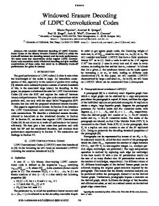
Fig. 1: System model for a encoded 4-ary transmission over ISI-channels with a punctured convolutional code and overall rate R = 4/3. The transmitter is composed of a rate-K/n binary convolutional encoder with generator polynomials [ gij ]; 1 ≤ i ≤ n; 1 ≤ j ≤ K, with K input symbols and n parallel output symbols at each time instant. At each output branch of the encoder, the symbols traverses through a non-linear timeinvariant puncturing system with periodic puncturing scheme Pi ; 1 < i ≤ n. For each encoder input symbol the puncturing scheme cyclically advances by one step. Whenever the scheme is zero, the current symbol at the output gets punctured (i.e., discarded), accordingly. The punctured output is mapped for a M -ary PAM transmission. The transmit signal traverses
through a memory-L discrete-time ISI-channel with L + 1 channel coefficients h[k] with k denoting the time index. The only requirement necessary for the matched decoding approach is that the rate-K/n convolutional code is matched to the M -ary modulation via M = 2n . For sake of simplicity, we here consider real-valued ASK, only. For clarity, we restrict ourselves to M = 4, but note that the concept can be extended to arbitrary M = 2n . III. M ATCHED D ECODING OF N ON -P UNCTURED C ODES In order to introduce maximum-likelihood sequence estimation (MLSE) for punctured codes, we first describe the encoding and mapping process for non-punctured convolutional encoding and natural labeling. We first ignore the ISI-channel for simplicity, i.e., L = 0, and later briefly recall our MD approach also considering an ISI-channel. Please note that here a single uncoded bit is encoded with a rate-1/2 convolutional encoder resulting in two coded bits, i.e., MSB and LSB, respectively. These coded bits contain the information of a single uncoded bit and are mapped onto a single transmit symbol m[k]. Thus, after mapping, the overall rate of the transmission is R = 1bit/symbol.
The resulting trellis is well-known and time-invariant as in each time step the same relation between input value, FSM state, and generator polynomials holds. B. Matched Decoding In the following, we recall the matched decoding approach briefly. As we derived in [3], the matched decoding approach combines the channel encoder with the ISI-channel in such a way, that fewer states are sufficient to describe the supertrellis. There, the rate-K/n convolutional code was matched to a 2n -ary ASK-transmission scheme. Instead of creating the super-trellis based on the M -ary channel, we represented the super-trellis based PL on log2 M = n parallel binary ISI-channels. With C = − k=0 h[k](M − 1) and the Gauss representation of the modulo operation the transmission can be represented as depicted in Fig. 3. There, the memory of the ISI-channel is binary only and a natural labeling is performed. This approach enables a first state reduction of the super-trellis without loss in minimum Euclidean distance. 2 +
�·�
× + − h[0] h[1] × ×
2
A. Description of the Finite State Machine Fig. 2 illustrates the encoding process (top) and the state transitions of the FSM (bottom) when no puncturing is involved. The uncoded unipolar information sequence u[k] ∈ {0, 1} is inserted into the FSM (light gray, ) as input values and later passes through all delay elements describing the state of the FSM (dark gray, ). Here, the generator polynomials gi , 1 < i < 2, process the input symbol together with the FSM state synchronously at each time instant. The resulting encoded bits, denoted with MSB and LSB, respectively, are naturally labeld and mapped to the 4-ary symbol alphabet of the transmission scheme, e.g., via m = 2(2MSB + LSB) − 1. g1
g1
g1
u[ν + 3]
g2
g1
u[ν + 2]
g2
g2
u[ν + 1]
g2
u[ν]
2 +
�·�
2 ×
+
× + − h[0] h[1] × ×
2
h[2] ×
2 C +×+
r[k]
h[2] ×
+
Fig. 3: Replacement of the mod 2 addition with the non-linear representation using floor function. (M = 4, i.e., n = 2, nonpunctured code). Figure 4 illustrates the state transitions of the transmitter FSM when non-punctured convolutional encoding and ISIchannel are considered jointly. ν+2 ν+1
ν
ν−1 ν−2 ν−3 h[0]
MSB
LSB
m[ν]
MSB
LSB
m[ν + 1] ν+2 ν+1
MSB
LSB
m[ν + 2] ν
ν−1 ν−2 g1
g2
h[1]
m[ν + 3]
h[0] h[1]
MSB
h[0] h[1]
MSB LSB
g2 g1
LSB
LSB
g2 g1
MSB
Fig. 4: State transitions of the FSM for matched decoding.
MSB LSB
Fig. 2: Top: Encoding process for a rate-1/2 convolutional code and 4-ary mapping. Overall transmission rate R = 1. Bottom: State transitions of the transmitter FSM and the relations between generator polynomials and FSM-state/input.
IV. M ATCHED D ECODING FOR P UNCTURED C ODES We now describe the encoding process and state transitions when punctured codes are used. We will discuss the FSM for punctured convolutional codes as well as the modifications necessary for the VA to run in the resulting trellis.
A. Description of the Finite State Machine When punctured convolutional codes are used, the strict relation between an uncoded information bit, n encoded bits and the mapped symbol is no longer valid. As can be seen from Fig. 5 (top), the third and seventh encoded symbol, for example, are punctured and do not contribute to the mapping process. Additionally, there is no strict relation between MSB, LSB and the output of the generator polynomials, anymore. The transitions of the FSM, depicted in Fig. 5 (bottom), show three differences when compared to non-punctured FSM transistions, cf. Fig. 2 (bottom). These are described subsequently. g1
g1
g1
g1
u[ν + 3]
× MSB
LSB
× MSB
m[ν]
g2
u[ν + 2]
g2
g2
u[ν + 1]
g2
u[ν]
LSB
MSB
m[ν + 1]
ν+5 ν+4 ν+3 ν+2 ν+1
LSB m[ν + 2]
ν
ν−1 ν−2 g1
Γ0
LSB
g2 g2
MSB
Γ1 g1 g2
Γ2 Γ0 g2
LSB MSB
Γ0
Γ1
Γ2
LSB
g2 g1
MSB
whenever no effect occurs for puncturing, i.e., an even number of puncturings occured up to time instant ν, and the generator polynomials are synchronized with LSB and MSB. Γ1 is used, whenever an odd number of puncturings has happened and Γ2 is used when an additional puncturing synchronize the generator polynomials with MSB and LSB again. The number of generator offsets needed to describe all steps depends on the size of the modulation alphabet whereas the generator offsets depend also on the puncturing scheme. 2) State Extension: The FSM transitions in Fig. 5 (bottom) show that the symbol m[ν + 1] contains information on the uncoded information bits u[ν + 1], for which the MSB output was punctured, and the consecutive information bit u[ν + 2]. We see that, when generating the output, the calculation of the LSB is one step ahead to the MSB and considers one extra information bit. This results in a trellis that has to be expanded (i.e., splitted) by a factor of two. This can be easily seen from the figure as the generator polynomials in the second step (generator offsets Γ1 ) now cover four blocks instead of just three. However, for a 4-ary transmission, when puncturing happens a second time, MSB and LSB are resynchronized with the generator polynomials and a so called merge happens in the trellis diagram.
MSB LSB
Fig. 5: Top: Encoding process for a rate-2/3 punctured convolutional code and natural labeling. Overall transmission rate R = 4/3. Bottom: State transitions of the transmitter FSM and the relations between generator polynomials and FSMstate/input. 1) Generator Offsets Γi : It becomes clear that the strict relation between the MSB, LSB and the generator polynomial g1 and g2 , respectively, no longer hold. The second symbol, i.e., m[ν +1], for example, contains information about u[ν +1] and u[ν + 2]. In addition, the MSB is now generated by g2 instead of g1 as was the case in the non-punctured approach. Accordingly, the LSB, which was generated by g2 in the nonpunctured case, is now generated by g1 . It is also clear that the third symbol is generated by u[ν + 2] and u[ν + 3] using the generator polynomial g2 twice. To handle these relations we introduce a set of so called generator offsets Γi which describe, depending on the puncturing scheme, the relations between generator polynomials, input value, FSM state, and mapping to MSB or LSB, respectively. For example, Γ1 indicates that the MSB output symbol is generated with the input value (light gray), the FSM state, and the generator polynomial g2 . On the other hand, to calculate the LSB we have to use the extension (hatched block, ) as input value so that g1 is one step ahead of the LSB. Therefore, the input value for the MSB is now part of the FSM state for the LSB. Note that, in the case of M = 4, Γ0 is used
Fig. 6: Super-trellis representation for a punctured rate-2/3 convolutional code. In the first to VA steps, two transitions arrive at each state, i.e., one bit can can be estimate, whereas the third step allows an estimation for two bits. Therefore, a trellis based decoding algorithm, such as the VA, has to be performed on a time-variant trellis diagram. As an example, Fig. 6 shows the resulting trellis diagram for a punctured convolutional code with a constraint length ν = 2. 3) Time Asynchronicity: The punctured code has a rate of RP = 2/3. As we can not insert Log-Likelihood Ratios (LLR) with L = 0 after equalization and before decoding, because of the joint trellises of equalization and decoding, the VA has to estimate four bits from just three received symbols to achieve the code rate. As one can see from the trellis in Fig. 6 the first two steps Γ0 have two transitions arriving at each state resulting in an estimation of a single bit per state. However, the last step Γ2 has four transitions into each state so that the decision for a survivor gives an estimate on two bits. The path register of the VA has to consider the fact that now four bits have been estimated within three received symbols. The last step can be described as a state merging, whereas the split is performed in the first step, e.g. by copying the state metrics of the first four states into the last four states.
ν+5 ν+4 ν+3 ν+2 ν+1
ν
ν−1 ν−2 ν−3 ν−4 ν−5 ν−6 h[0]
Γ2 Γ1
h[1] h[0]
Γ0 Γ2
h[1] h[0]
Γ1 Γ0
h[1] h[0]
Γ2 Γ1 Γ0 Γ2
h[1] h[0] h[1]
Fig. 7: State transitions of the transmitter FSM with R = 4/3 and the relations between generator polynomials, FSM-state/input and channel state for a memory-1 ISI-channel. B. Viterbi Modifications for Punctured Codes As mentioned above the VA has to estimate four bits within three symbols from the trellis transitions. To see the modifications of the VA we need to consider the state extension. Using Fig. 5 (bottom), we define in each step Γ0 , . . . , Γ2 the input value to be the first value which is used by either g1 or g2 . As a result, in step Γ0 the values at time instants k = {ν; ν + 4} can be defined as input values. When in step Γ1 or Γ2 , the input value is at time instant k = {ν + 2; ν + 3} (e.g., the hatched values, ). Unfortunately we can not estimate the input value u[ν + 2] in Γ1 because parts of the information has not been received, yet, (i.e., missing information is located in the MSB in Γ2 ). However, as all information on u[ν + 1] (for which the output of g1 was punctured) has been received we can estimate it. To do so we have to evaluate the most significant bit of the survivor state which is selected by the VA. In Γ2 , as already mentioned, selecting the survivor path allows a decision for two information bits (the most significant bit of the survivor and the input value) because four transitions end in each state, here. For implementations, keep in mind that the VA is thus running asynchronously to the desired information sequence at the output to achieve the overall rate R = 4/3. C. Matched Decoding The above description now enables the extension for supertrellis decoding of punctured convolutional coded transmission over ISI-channels. To extend matched decoding for punctured codes, one must ensure that the right generator offsets Γi are involved at the right time. Once the encoding and mapping is executed (here natural labeling and 4-ASK modulation are considered), the symbols traverse through the ISI-channel independent from the encoding and puncturing process. For an ISI-channel with two taps (channel memory L = 1), for example, two output symbols of the mapper are involved at each time instant. Thus, two out of the existing three generator offsets Γi and Γ(i−1) mod 3 have to be considered. This can be seen from Fig. 7. For a memory-1 channel, in the third step (generator offset Γ2 ), m[ν+2] is received and the ISI-channel memory contains m[ν + 1] which was generated
in the previous time instant using generator offset Γ1 . The resulting overall generator offsets are depicted in Fig. 7. This scheme can easily be extended to arbitrary lengths of the ISIchannel. V. N UMERICAL R ESULTS The effectiveness of the approach of punctured MD is now verified by means of numerical simulations. We restrict ourselves to rate-1/2 encoding schemes and a 4-ary modulation alphabet. As convolutional encoder we apply the generator polynomials [5oct ; 7oct ] which, in combination with Gray labeling, results in a trellis coded modulation scheme (TCM) for M -ary ASK. The puncturing scheme is defined as P1 = { 1; 0 } and P2 = { 1; 1 } as shown in Figure 1 and 5. Thus, the overall transmission rate is R = 4/3. Please note, that this combination of encoder, puncturing scheme, and mapper may not be the optimum choice. However, it allows a comprehensible description of our approach. For simplicity an exemplary minimum phase ISI-channel is generated by h[k] = α2 =
1 L−k+1 · ; α L+1 � �2 L X L−k+1 k=0
L+1
0≤k≤L
(1) (2)
and normalized to unit energy. Please note that due to the normalization the equivalent energy per bit Eb is identical at transmitter output and receiver input. The applied ISIchannel is described by (1) using L ∈ {2; 3; 4} with Zcha = {16; 64; 256} states, respectively. The simulation results in Fig. 8 shown the bit error rate (BER) over an ISI-AWGN-channel with ratio of energy per Eb information bit and one-sided power spectral density N . 0 Our MD approach of the VA operating on the time-variant equivalent non-linear trellis description is compared to separate equalization and decoding employing DFSE/BCJR [6] for equalization and full-state VA for decoding. Please note that by dispensing the interleaver between channel encoding and modulation for the separated approaches, block errors that
100
100
MD (64 states)
MD (128 states) DFSE-VA (4+4 states)
DFSE-VA (4+4 states)
DFSE-VA (16+4 states)
DFSE-VA (16+4 states)
10−1
10−1
BCJR-VA (16+4 states)
DFSE-VA (64+4 states)
BER
BER
BCJR-VA (64+4 states)
10−2
10−2
10−3
10−3 Zenc = 24 , Zcha = 42 10−4
3
5
7
10 log10
9
�
Eb N0
Zenc = 22 , Zcha = 43 11
�
13
10−4
15
3
5
7
10 log10
in dB
9
�
Eb N0
11
�
13
15
in dB
Fig. 8: Bit error performance for convolutionally encoded 4-ASK transmission (gray labeling) with overall rate R = 4/3 over 0 the ISI-AWGN-channel. Generator polynomials [5oct ; 7oct ] (Zcha = 4). Left: Memory-2 ISI-channel (L = 2, i.e., Zcha = 16). Right: Memory-3 ISI-channel (L = 3, i.e., Zcha = 64).
10
100
are caused by the equalization process reduce the ability to decode due to correlated errors. Obviously, the soft-decision separated approach results in improved −1bit error rates when compared to to hard-decision separated approach. However, the separated equalization and decoding approach is significantly outperformed by MD as decoding is carried out in the super-trellis. Note that the results are well-known for supertrellis decoding but are achieved with fewer states due to the −2 equivalent non-linear trellis description. We also conducted simulations for larger trellises as shown in Fig. 9. There, the convolutional code can be described with a four-state FSM and the ISI-channel has five taps resulting in 256 states, for a 4-ary ASK-transmission. In the case of a non-punctured code the straigt-forward super-trellis −3 has 1024 states. The matched decoding approach reduces the super-trellis to only 64 states using a non-linear trellis description [3]. However, for a punctured convolutional code, the time-variant super-trellis would have 1024 states,enc and 2048 states when splitted. The matched decoding approach allows a state reduction to 256 and 512 states,−4 respectively. Apparently, already for moderate encoder size and short ISI-channels, super-trellis decoding becomes intractable, when the code is punctured due to the state expansion. Therefore, we also implemented an algorithm to perform the VA on a reduced set of states. Due to lack of space we can not describe the modification to the reduced-state sequence estimtion (RSSE) in full detail, here. The state partitioning needed for RSSE uses the minimum-phase charateristic of the impulse response of the ISI-channel and can be related to decision feed-back sequence estimation, a partial solution of RSSE. A detailed description on the application of RSSE of non-punctured convolutional codes can be found in [3]. The simulation results shown in Fig. 9 indicate, that our MD-RSSE approach for punctured convolutional codes enables efficient super-trellis decoding and also allows a trade-off between complexity and performance, i.e., noise-robustness can be achieved. Obviously, the proposed decoding scheme significantly supersedes the separated equalization and decoding approaches already for only 16 states.
MD-RSSE (16-states)
10−1
10
3
BER
MD-RS
BER
MD (512-states, STD) DFSE (4)/VA (4)
10−2
DFSE (64)/VA (4) BCJR (64)/VA (4)
10−3
3
5
7
9
10 log10
�
Eb N0
DFSE ( 11
�
13
15
DFSE (
in dB
BCJR (
Fig. 9: Bit error performance for convolutionally encoded 4ASK transmission (gray labeling) with overall rate R = 4/3 over memory-4 the ISI-AWGN-channel (Zcha = 256) with 2Generator polynomials 4 [5oct ; 7oct ] (L = 4, i.e., Zcha = 256). VI. C ONCLUSION
7
9
11
13
15
In this paper we have shown that it is possible to perform trellis decoding of punctured convolutional encoded transmissions. We extended the well-known decoding approach for the Eb and described the differences of matched use over ISI-channels 10 between N0 non-punctured and punctured codes. By decoding using RSSE with DFSE-like partitioning we obtain an efficient method for a trade-off between complexity and performance.
10 log
MD (51
DFSE ( Zenc = 22 , Zcha = 44
10−4
MD-RS
DFSE (16)/VA (4)
= 2 , Zcha = 4 5
MD-RS
MD-RSSE (32-states) MD-RSSE (128-states)
10
Z
MD-RS
MD-RSSE (8-states)
10
10
MD-RSSE (4-states)
MD-RS
�
�
in dB
R EFERENCES [1] T. Hehn and J. Huber, “LDPC Codes and Convolutional Codes with Equal Structural Delay: A Comparison,” IEEE Transactions on Communications, vol. 57, no. 6, pp. 1683–1692, Jun. 2009. [2] E. Zehavi, “8-PSK Trellis Codes for a Rayleigh Channel,” Communications, IEEE Transactions on, vol. 40, no. 5, pp. 873 –884, May 1992. [3] F. Schuh, A. Schenk, and J. Huber, “Reduced Complexity Super-Trellis Decoding for Convolutionally Encoded Transmission Over ISI-Channels,” ArXiv e-prints, Jul. 2012. [4] J. Huber, Trelliscodierung: Grundlagen und Anwendungen in der digi¨ talen Ubertragungstechnik. Springer, 1992. [5] A. Viterbi, “Error Bounds for Convolutional Codes and an Asymptotically Optimum Decoding Algorithm,” Information Theory, IEEE Transactions on, vol. 13, no. 2, pp. 260 –269, Apr. 1967. [6] L. Bahl, J. Cocke, F. Jelinek, and J. Raviv, “Optimal Decoding of Linear Codes for Minimizing Symbol Error Rate (Corresp.),” Information Theory, IEEE Transactions on, vol. 20, no. 2, pp. 284 – 287, Mar. 1974.