attached to a digital multimeter for four-point measurement. An additional silver epoxy contact. (contact number 5 in figure 1) was used to apply the voltage ...
Mat. Res. Soc. Symp. Proc. Vol. 699 © 2002 Materials Research Society
Materials Characterization Heterostructure
and
Device
Performance
of
a
CMR-Ferroelectric
S. R. Surthi, S. Kotru, and R. K. Pandey Department of Electrical and Computer Engineering The University of Alabama, Tuscaloosa, AL 35487-0286, U.S.A. ABSTRACT The films of colossal magnetoresistive La0.67Ca0.33MnO3 (LCMO) and ferroelectric SbSI were grown by pulsed laser deposition method for fabricating their heterostructures. By varying the processing conditions during film growth and controlling subsequently the annealing conditions, the resistivity transport properties of the LCMO films could be greatly modified. Preliminary tests on the ferroelectric field effect transistor (FeFET) based on LCMO-SbSI heterostructure showed that the device behaves like a nonvolatile memory element. The FeFET showed a maximum channel modulation of ~10% at room temperature, and the switching voltage was less than 2 V.
INTRODUCTION Since the discovery of colossal magnetoresistance (CMR) in the early 1990s, the Mn-based perovskite oxides of the form R1-xBxMnO3 (R = rare earth, B = divalent cations like Ca, Sr, Ba) have experienced a huge resurgence [1-3]. This has triggered intense studies on the fundamental physics and the future industrial applications of these materials. Under a certain range of doping, these oxides exhibit simultaneous electronic and magnetic transitions, where the magnetic Curie temperature (TCM) marks a transition from a high temperature paramagnetic insulator (or semiconductor) to a low temperature ferromagnetic metal. Additionally, the magnetic and transport properties of CMR materials are very sensitive to the oxygen content and doping and can be changed by varying the materials processing conditions. A measurable field effect, i.e. field induced modulation of resistance, has also been reported in the CMR manganates [4]. This effect is independent of field-direction and occurs above TCM, where the temperature dependence of resistivity is semiconductor-like (i.e. activated resistivity transport). This makes the CMR oxides a likely candidate for use as semiconductors in novel field effect transistors with ferroelectric gate. These devices can be interrogated by reading the resistance (or conductance) of the CMR-based channel. Unlike ferroelectric capacitive memory elements, the act of reading does not affect the state of the device and hence the memory readout is nondestructive. Even though the ferroelectric field effect transistors (FeFETs) have been studied since the 1950s [5-8] an acceptable nonvolatile memory element with adequate retention and write-erase speed has not been demonstrated. This is mainly due to the difficulty in controlling the interface between the ferroelectric and semiconductor [9]. Recently, researchers have proposed the use of all-perovskite ferroelectric/semiconductor heteroepitaxial structures to improve upon the quality of the interface [10]. Most of the heterostructure devices reported so far are based on ferroelectric Pb-Zr-Ti-oxide (PZT) or related perovskite oxides [9-12]. In this paper, we report the properties of thin films of La0.67Ca0.33MnO3 (LCMO) and the effect of substrate temperature and oxygen post-annealing on resistivity of the films. We have R10.2.1
also built a ferroelectric FET (FeFET) with ferroelectric antimony sulpho iodide (SbSI) as a gate insulator and LCMO film as a semiconductor. SbSI has the advantage of low processing and annealing temperatures (up to 250 oC) as compared to perovskite ferroelectrics like PZT (typically 600-900 oC). Ferroelectric SbSI is a group V-VI-VII compound, and it crystallizes in orthorhombic structure (a = 8.49 Å, b = 10.1 Å, and c = 4.16 Å) with the c-axis being the polar axis [13]. In the SbSI films, we have observed a peak dielectric constant of up to ~5000 with a ferroelectric Curie temperature TCF of 18-21 oC [14]. These films show a diffused transition from ferroelectric to paraelectric state. Even though the TCF is around room temperature these SbSI films exhibit a small remnant polarization at and above room temperature up to ~40 oC [15].
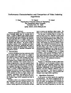
EXPERIMENTAL DETAILS We have fabricated thin films of LCMO and the LCMO-SbSI heterostructures by the pulsed laser deposition (PLD) technique. Thin films of LCMO (50-140 nm) were grown on single crystal NdGaO3 substrates at different conditions to analyze the effect of various processing parameters on the properties of the LCMO films. The details about LCMO ceramic target preparation and PLD growth of films are presented elsewhere [15, 16]. The as-grown LCMO films were annealed in flowing oxygen in a tube furnace at 600-900 oC for 0.5-12 hours [15]. The film of ferroelectric SbSI was later grown on the annealed film of LCMO. Before mounting these samples on the substrate holder, the LCMO film was masked in such a way that an area of about 3 mm x 6 mm in the center of the film remained exposed for the SbSI film growth. The SbSI films were grown by PLD at room temperature. The LCMO-SbSI heterostructure was post- annealed at 200-250 oC for 5-15 minutes in air to promote crystallinity in SbSI. The schematic of the heterostructure with gate, source, and drain contacts is shown in figure 1. Here, the area of LCMO film underneath the SbSI film forms the channel for the FeFET.
Pt top electrode
5
Gate
Silver wire contacts
3 6
SbSI film
4 Drain
1
Source
LCMO film
NdGaO3 Substrate
2
Figure 1. Schematic of the ferroelectric field effect transistor (FeFET) based on LCMO-SbSI heterostructure. R10.2.2
For electrical measurements on the heterostructure, a Pt electrode was sputter deposited on the SbSI film. Electrical connection from this electrode was made by silver wire and an epoxy. Other electrodes on the LCMO films were also formed similarly. The resistivity of the LCMO films was measured by the van der Pauw four-point technique. Structural analysis was performed using x-ray diffraction (XRD) and film thickness and composition was determined by Rutherford backscattering spectroscopy (RBS).
RESULTS AND DISCUSSION Figures 2 (a) and (b) show the resistivity versus temperature for LCMO films grown at a substrate temperature of 700 and 800 oC. The oxygen partial pressure was 100 mTorr for both experiments. Films grown at 700 oC show a metal to semiconductor transition, as shown in figure 2 (a). These films were annealed in oxygen at 850 oC for 3 and 12 hours, respectively. As the annealing time was increased, the Tp (temperature at resistivity peak) increased from 119 K to 169 K, whereas ρp (peak resistivity corresponding to Tp) decreased from 19.93 Ω-cm to a substantially lower value of 0.72 Ω-cm. The films grown at a substrate temperature of 800 oC were also annealed at 850 oC for 0.5 and 3 hours. The film annealed for 0.5 hours did not show a transition to metallic state (measured down to ~80 K), whereas the film annealed for 3 hours showed a transition at Tp of 110 K (figure 2 (b)). The ρp for this thin film was 41.2 Ω-cm. Hence, we observe that ρp increased as the substrate temperature increased from 700 to 800 oC, whereas Tp of the film decreased with increasing substrate temperature. With the same ceramic targets, another PLD experiment was carried out at a substrate temperature of 600 oC. Concurrently, the oxygen partial pressure was increased from 100 to 200 mTorr. The resistivity for these two films, post-annealed at 850 oC and 900 oC for 0.5 hours, is plotted in figure 3. Comparing the resistivity in figures 2 and 3, we can conclude that the Tp substantially increased with decreasing substrate temperature and increasing oxygen partial pressure. The Tp is 211 K and 277 K for samples deposited at 600 oC versus 110-169 K for thin films grown at 700-800 oC. The films deposited at 600 oC also exhibited lower ρp.
1000
100
Film thickness = 86 nm
Resistivity (Ω -cm)
10
Substrate temperature = 800 °C O2 partial pressure = 100 mTorr 100
Post-annealed at 850 °C for 3 hr
(169 K, 0.7187 Ω-cm)
1
0.1
(a)
Post-annealed at 850 °C for 12 hr
Resistivity (Ω -cm)
(119 K, 19.931 Ω-cm)
(110 K, 41.2 Ω-cm)
10
Film thickness = 90 nm
Post-annealed at 850 °C for 0.5 hr
1
0.1
0.01 Substrate temperature = 700 °C O2 partial pressure = 100 mTorr
(b)
Post-annealed at 850 °C for 3.0 hr
0.01
0.001 0
50
100
150 200 Temperature (K)
250
300
350
0
50
100
150 200 Temperature (K)
250
300
Figure 2. Effect of annealing time on the resistivity of two different sets of LCMO films grown at substrate temperature of (a) 700 oC and (b) 800 oC. R10.2.3
350
10 Film thickness = 104 nm
(211 K, 2.122 Ω-cm)
Resistivity (Ω-cm)
1
0.1 Post-annealed at 850 °C for 0.5 hr
(277 K, 0.0449 Ω-cm)
0.01 Post-annealed at 900 °C for 0.5 hr
0.001
Substrate temperature = 600 °C O2 partial pressure = 200 mTorr
0.0001 0
50
100
150 200 Temperature (K)
250
300
350
Figure 3. Effect of annealing temperature on the resistivity of LCMO thin films deposited at a substrate temperature of 600 oC.
The results show that the transport properties of LCMO films are extremely sensitive to the process conditions during film growth or subsequent annealing. A summary of the resistivity data (peak temperature and resistivity) and the processing conditions during film growth and post-annealing is presented in table I. Two processes, namely, film deposition at higher temperature and post-annealing in oxygen at high temperature, have opposite influence on the resistivity behavior of LCMO films in this study. A higher deposition temperature (i.e., the substrate temperature) resulted in a higher ρp and a lower Tp. Annealing the films in oxygen atmosphere at higher temperatures (or for longer time) reduces the ρp and shifts the Tp to a higher temperature. These opposite effects can be understood by considering the variation of the oxygen content during film deposition and subsequent annealing. The hole doping (i.e., partial doping of La3+ with Ca2+) creates the Mn mixed valence in LCMO type oxides, which in turn, gives rise to ferromagnetism and metallic behavior [17, 18]. The mixed valence ratio
Table I. Summary of the film growth conditions, post-annealing details and the resistivity transport behavior for La0.67Ca0.33MnO3 thin films. Substrate Temperature (oC) 600
O2 pp (mTorr)
700
100
800
100
200
O2 Annealing Temperature Time (hrs) (°C) 850 0.5 900 0.5 850 3 850 12 850 0.5 850 3
R10.2.4
Tpeak (K)
ρpeak (Ω-cm)
211 2.122 277 0.045 119 19.931 169 0.719 No transition 110 41.2
(Mn3+/Mn4+) can also be controlled by varying the oxygen content. During film growth by PLD, higher deposition temperatures result in more oxygen deficiency [19]. An annealing process in oxygen atmosphere can compensate the oxygen deficiency. Thus the oxygen introduced by annealing leads to an increased oxygen state of the Mn3+ ions to Mn4+ due to charge disproportionation [19, 20]. This change in the Mn3+/Mn4+ ratio subsequently shifts the ferromagnetic transition temperature (TCM) or the peak temperature (Tp) where a metal to semiconductor transition is observed. Similarly, increasing the oxygen partial pressure during the film growth will increase the oxygen content and, hence, decrease the ρp and shift the Tp to higher temperature. A small composition change during the film deposition also cannot be ruled out, especially at higher substrate temperature [18]. Figure 4 shows the XRD pattern (θ-2θ scan) for a typical LCMO film after oxygen annealing. Only two peaks, corresponding to (002) and (004) orientations are observed, confirming the epitaxial nature of the film (c-axis oriented). The LCMO films have a very small lattice mismatch (< 1%) with NdGaO3 substrate and, hence, the substrate peak is almost indistinguishable from the film peak. The RBS analysis was also employed to measure the thickness of the LCMO films. The film thickness was found to be 104 nm, 86 nm, and 90 nm for films deposited at 600, 700, and 800 oC, respectively. The RBS elemental analysis suggests that the actual film composition is very close to the nominal target composition of La0.67Ca0.33MnOZ. For the FeFET based on LCMO-SbSI heterostructure, the channel modulation is indicative of the quality of the device. The modulation, which represents the change in the channel resistance with applied gate voltage, can be quantified as % channel modulation. To characterize the device, the two contacts on the source and drain side (contact numbers 1-4 in figure 1) were attached to a digital multimeter for four-point measurement. An additional silver epoxy contact (contact number 5 in figure 1) was used to apply the voltage between drain and gate. During the measurements, voltage was applied to the ferroelectric and a wait time of 3 s was used after removing the poling voltage. This allowed any switching transients in the ferroelectric to die 2000
(004) LCMO (004)NdGaO3
Intensity (arb. units)
1600
1200
800
(002) LCMO (002)NdGaO3
400
0 10
20
30
40 50 2 Theta (deg)
60
70
80
Figure 4. A typical XRD pattern for PLD grown thin films of La0.67Ca0.33MnO3 on single crystal substrate NdGaO3.
R10.2.5
down. Then the channel resistance of the FeFET was read off the digital multimeter. Hence, the gate was actually floating when the channel resistance was measured. Figure 5 shows the hysteresis loop obtained by measuring the channel resistance as a function of the poling voltage, which is opposite of the actual gate voltage. For this FeFET, the thickness of the LCMO and SbSI films was 85 nm and 2 µm, respectively. Based on figure 5, the % channel modulation can be calculated as [(Rmax-Rmin)*100/Rmin], where Rmax and Rmin represent the maximum and minimum channel resistance, respectively. Our integrated device showed a maximum channel modulation of approximately 10% and all measurements were performed at room temperature. The LCMO thin film, which acts as the semiconductor in this FeFET, is a p-type semiconductor because of the hole doping (i.e. partial substitution of La3+ by Ca2+). Assuming a p-type semiconducting behavior of LCMO, the channel modulation effect observed here can be attributed to a field effect. When a positive voltage is applied to the gate (i.e. negative poling voltage), the ferroelectric SbSI polarizes so that the electric dipoles are pointing down into the LCMO film. The polarization effect causes a build-up of positive charge on the bottom side of the ferroelectric film. In order to maintain the ‘charge neutrality’ at the LCMO-SbSI interface, there will be a build-up of negative charge carriers in the LCMO channel near the interface. Hence, we can say that the p-type LCMO channel is now depleted of the majority carriers (i.e., positive charged carriers). This explains the increase in the channel resistance when the applied gate voltage is positive [9]. Conversely, when a negative gate voltage is applied (i.e positive poling voltage), the negative charges in the ferroelectric tend to be compensated by positive charge carriers in the LCMO channel. This is equivalent to accumulation of holes, the majority carriers, in a p-type material like LCMO. In this case, the channel resistance decreases. Based on the results in figure 5 and the clockwise direction of the hysteresis loop, it can be confirmed that the channel modulation was the result of a field effect.
Channel Resistance (kΩ)
32 Rmax 31 Channel modulation ~ 10% 30
29 Rmin 28 -3
-2
-1
0
1
2
3
Poling Voltage (V)
Figure 5. Channel modulation of a ferroelectric FET based on LCMO-SbSI heterostructure measured at room temperature.
R10.2.6
The LCMO-SbSI heterostructure is also expected to behave like a nonvolatile memory element. The remnant polarization of the ferroelectric allows the device to retain its memory state (i.e. high or low resistance state) even when the power is tuned off. To test the retention of low (or high) resistance state, a positive (or negative) gate voltage was applied for a few seconds and switched off. The resistance of the LCMO channel was measured for about two hours after a wait time of three seconds. The observed change in channel resistance was less than 1%, showing good retention properties. An advantage of using CMR manganates as the semiconductor in the FeFET is that the memory device can be tuned both electrically as well as magnetically. Additionally, ferroelectric SbSI is also an excellent infrared detector material, which potentially can allow the device to be tuned optically [21].
CONCLUSIONS We have achieved a ferroelectric field effect in the heterostructure of ferroelectric SbSI and p-type semiconducting LCMO. The films of LCMO and SbSI were grown by pulsed laser deposition method. The transport properties of the LCMO films are very sensitive to the processing conditions, which modify the oxygen content of the oxide. When the films were deposited at lower temperature or annealed at higher temperature or longer time, the temperature at resistivity peak was higher and the resistivity was lower. The field effect observed in LCMOSbSI heterostructure based memory device showed a channel modulation of ~10% at room temperature. The field effect also confirms that the semiconducting LCMO film is a p-type conductor, as expected for a hole doped system. The switching voltage of the nonvolatile memory device was less than 2 V, which is smaller than similar devices based on ferroelectrics like PZT. The preliminary investigations suggest that the CMR manganates and SbSI are desirable materials for the fabrication of FeFETs for nonvolatile memory applications.
ACKNOWLEDGMENTS This work was supported in part by Advanced Technologies Program (ATP) of the Texas Higher Education Coordinating Board and the Texas Engineering Experimentation Station (TEES)/NSF Center for Electronic Materials, Devices and Systems at Texas A&M University. The authors would also like to thank the Materials for Information Technology (MINT) Center and the School of Mines and Energy Development (SOMED) at the University of Alabama for allowing the use of their materials characterization facilities. One of the authors (SRS) acknowledges the graduate school at the University of Alabama for the grant of a fellowship to pursue this research.
REFERENCES 1. R. von Helmolt, J. Wecker, B. Holzsapfel, L. Schultz and K. Samwer, Phys. Rev. Lett. 63, 2331 (1993). 2. S. Jin, T.H. Tiefel, M. McCormack, R.A. Fastnatcht, R. Ramesh and L.H. Chen, Science 264, 413 (1994). R10.2.7
3. C. N. R. Rao and A. K. Raychaudhari, “Colossal Magnetoresistance, Charge Ordering and Other Novel Properties of Manganates and Related Materials,” in Colossal Magnetoresistance, Charge Ordering and Related Properties of Manganese Oxides, edited by C. N. R. Rao and B. Raveau, World Scientific Publishing, Singapore (1997). 4. S. B. Ogale, V. Talyansky, C. H. Chen, R. Ramesh, R. L. Green, and T. Venkatesan, Phys. Rev. Lett. 77, 1159 (1996). 5. D. H. Looney, U.S. Patent No. 2791758 (1957); W. L. Brown, U.S. Patent No. 2791759 (1957); I. M. Ross, U.S. Patent No. 2791760 (1957); J. A. Morton, U.S. Patent No. 2791761 (1957). 6. P. M. Heyman and G. H. Heilmeier, Proc. IEEE 54, 842 (1966). 7. S. S. Perlman and K. H. Ludewig, IEEE Trans. Electron Devices ED-14, 816 (1967); G. G. Teather and L. Young, Solid State Electron 11, 527 (1968). 8. S. Y. Wu, IEEE Trans. Electron Devices ED-21, 499 (1974); Y. Higuma, Y. Matsui, M. Okuyama, Y. Nakagawa, and Y. Hamakama, Jpn. J. Appl. Phys. Suppl. 17-1, 209 (1978). 9. S. Mathews, R. Ramesh, T. Venkatesan, and J. Benedetto, Science 276, 238 (1997). 10. Y. Watanabe, Appl. Phys. Lett. 66, 1770 (1995); C. H. Ahn, J. -M. Triscone, N. Archibald, M. Decroux, R. H. Hammond, T. H. Geballe, Ø. Fischer, and M. R. Beasley, Science 269, 373 (1995). 11. C. H. Ahn, R. H. Hammond, T. H. Geballe, M. R. Beasley, J. -M. Triscone, M. Decroux, Ø. Fischer, L. Antognazza, and K. Char, Appl. Phys. Lett. 70, 206 (1997). 12. W. Wu, K. H. Wong, C. L. Mak, C. L. Choy, and Y. H. Zhang, J. Appl. Phys. 88, 2068 (2000). 13. E. Fatuzzo, G. Harke, W. J. Merz, R. Nitsche, H. Roetschi, and W. Ruppel, Phys. Rev. 127, 2036 (1961); R. Nitsche, and W. J. Merz, J. Phys. Chem. Solids 13, 154 (1960). 14. S. Kotru, W. Liu and R. K. Pandey, Proceedings of the 12th IEEE International Symposium on Applications of Ferroelectrics, (2001) 231. 15. S. R. Surthi, Ph.D. Dissertation, The University of Alabama (2001). 16. S. R. Surthi, S. Bhat, R. K. Pandey, K. D. D. Rathnayaka, A. Parasiris, A. C. DuMar and D. G. Naugle, Integrated Thin Films and Applications, Ceramic Transactions (86), 109 (1997). 17. G. H. Jonker and J. H. van Santen, Physica 16, 337 (1950); G. H. Jonker, Physica 22, 337 (1956). 18. G. C. Xiong, Q. Li, H. L. Ju, S. N. Mao, L. Senapati, X. X. Xi, R. L. Green, and T. Venkatesan, Appl. Phys. Lett. 66, 1427 (1995). 19. W. Zhang, W. Boyd, M. Elliot, and W. Herrenden-Harkerand, Appl. Phys. Lett. 69, 3929 (1996). 20. K. Raychaudhari, Adv. Phys. 44, 21 (1995). 21. J. F. Li, D. Viehland, A. S. Bhalla, and L. E. Cross, J. Appl. Phys. 71, 2106 (1992).
R10.2.8