Hindawi Publishing Corporation Journal of Applied Mathematics Volume 2014, Article ID 747134, 11 pages http://dx.doi.org/10.1155/2014/747134
Research Article Mathematical Modeling of a Multilayered Drift-Stabilization Method for Micro-UAVs Using Inertial Navigation Unit Sensor Hyeok-June Jeong,1 Myunggwon Hwang,2 Hanmin Jung,2 and Young-guk Ha1 1
Department of Computer Science & Engineering, Konkuk University, Neungdong-ro 120, Gwangjin-gu, Seoul 143-701, Republic of Korea 2 Department of Computer Intelligence Research, Korea Institute of Science and Technology Information (KISTI), 245 Daehak-ro, Yuseong-gu, Daejeon 305-806, Republic of Korea Correspondence should be addressed to Young-guk Ha;
[email protected] Received 19 February 2014; Accepted 6 May 2014; Published 22 June 2014 Academic Editor: Young-Sik Jeong Copyright © 2014 Hyeok-June Jeong et al. This is an open access article distributed under the Creative Commons Attribution License, which permits unrestricted use, distribution, and reproduction in any medium, provided the original work is properly cited. This paper proposes a multilayered quadrotor control method that can move the quadrotor to the desired goal while resisting disturbance. The proposed control system is modular, convenient to design and verify, and easy to extend. It comprises three layers: a physical layer, a displacement control layer, and an attitude control layer. The displacement control layer considers the movement of the vehicle, while the attitude control layer controls its attitude. The physical layer deals with the physical operation of the vehicle. The two control layers use a mathematical method to provide minute step-by-step control. The proposed control system effectively combines the three layers to achieve drift stabilization.
1. Introduction Unmanned aerial vehicles (UAVs) are expected to become a major part of the aviation industry as they can perform tasks such as traffic control, video recording, reconnaissance, and surveillance. Concomitant with developments in computer science, automatic control, sensors, and communications technologies, the quadrotor, in particular, is being evaluated as a suitable platform for small UAVs. Among its many advantages is the fact that it can move both vertically and horizontally, it can be made very small, and it can carry a variety of electrical devices. A quadrotor flies by means of four propellers, which are controlled by an automatic system programmed in a microprocessor. This means that the control system has minute control over its flight. Consequently, it is relatively easier to fly a quadrotor than other aircrafts such as helicopters and airplanes. However, controlling the desired behavior of the quadrotor is never easy. Because it flies in air, the quadrotor has to overcome inertia and undesirable wind disturbance.
Consequently, in order for the quadrotor to be useful, it has to have an effective control system. Efforts have previously been made to solve this problem; however, this goal has not yet been definitively achieved. The control systems proposed thus far are more complicated than effective. Some researchers have proposed vision-based control systems; however, such systems are inefficient and heavy and therefore not suitable for small UAVs. In this paper, we propose a quadrotor control system that uses the four motors and nine EOF-axis inertial navigation sensors, which measure the quadrotor’s attitude and movement, to achieve minute control. The control system operates on the basis of positioning; that is, it can move the quadrotor to any desired point while resisting external forces such as wind. Of course, drift stabilization is possible in any current position. In particular, the proposed control system is implemented in a modular form, so its design efficiency and performance can be easily verified. The proposed controller significantly increases the quadrotor’s stability and hovering performance and thereby facilitates the use of the quadrotor for various applications.
2
2. Related Work Over the past decade, much research has been devoted to quadrotor control systems, a large portion of which has focused on the use of vision. Grzonka et al. [1] pioneered work in this area. Their research focused on indoor quadrotor flight control systems that are able to pilot the quadrotor in indoor spaces via real-time image processing [2]. However, even though their research is excellent, the stability of their control system is in doubt. Bills et al. [3] also proposed a control system that uses vision; however, their proposed system cannot guarantee stable quadrotor movement. Romero et al. [4] proposed a control system that uses optical signals. The proposed system is stable because it only traces certain points. Gu et al. [5] focused their research on systems flying in formation, with each UAV designed hierarchically according to its role, such as flight leader or wingman. These systems have the advantage of stability but are limited to operating only in particular situations. Zhang et al. [6] proposed a control system that combines vision with an IMU sensor. The system is stable; however, the efficiency of the control system is poor—it performs well for small vehicles but is too large for microquadrotors. Consequently, in spite of research efforts expended to date, a suitable implantable control system for micro-UAVs has not been realized. We believe our proposed multilayered drift-stabilization method can provide an effective solution that resolves these problems.
Journal of Applied Mathematics Displacement feedback (double integration)
Displacement PID
Target angle
Displacement control layer
Pitch roll yaw angle feedback (sensor)
Motor control
Pitch, roll, yaw PID
Attitude control layer
Motor
Sensor
MCU
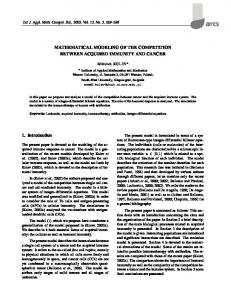
3. Design of the Proposed Control System In this section, we discuss the design of the proposed control system in terms of its layers and the algorithms used by each layer. 3.1. The Combined Layers. Our proposed multilayered control system has advantages in terms of its design, verifiability, and extendibility. These advantages result from the fact that each control layer is in charge of an assigned function. That is, each layer is considered to be abstracted. The architecture of our proposed multilayered driftstabilization control system is depicted in Figure 1. It comprises three layers. The first layer consists of physical components such as motor, frame, rotor, and battery. The rotation of the motor is controlled in accordance with a control value. The sensor calculates such parameters as the angular velocity and acceleration and passes the feedback values to the other layers. The second layer, the “attitude control layer,” is in charge of the attitude angle, “roll, pitch, and yaw.” The attitude control layer receives attitude feedback and an objective angle. However, the layer does not care about how the actual angle is calculated. This layer is simply responsible for ensuring that the quadrotor is at the correct angle received. Finally, the “displacement control layer” is in charge of the movement of the vehicle. This layer receives displacement feedback and control signals (reference) that it uses to calculate an appropriate angle to pass to the attitude control layer. The displacement control layer does not care how the
Physical layer (UAV)
Figure 1: Architecture of the multilayered drift-stabilization control system.
angle of the vehicle is controlled. This is why we say that the control system design is abstracted. Consequently, the proposed multilayered control system can be a powerful and convenient system, in which each section only fulfills its specified roles. 3.2. The Physical Layer. A quadrotor has four rotors and four motors on a rigid framework. A sensor is mounted at the center of the frame for accurate operations. Other components, such as circuit and batteries, are mounted in the same position as the sensor to ensure a balanced center of gravity. Our proposed control system is designed for the shape shown in Figure 2 and takes into consideration the dynamics of this shape. Despite the shape of the camera, the quadrotor is assumed to be symmetrical in quality and structure. The physical characteristics of the quadrotor are listed in Table 1. In order to establish the dynamic model of the quadrotor, we can make the following general assumptions. (i) Gravity and resistance of the quadrotor are not affected by flight altitude and other factors.
Journal of Applied Mathematics
3 F4
F1
z y F3
x F2
g
Figure 2: Physical appearance/shape of a quadrotor. Figure 3: Definition of axis and rotor output.
Table 1: Quadrotor physical parameters. Parameters
Value
𝐼𝑥 𝐼𝑦 𝐼𝑧
7.5 × 10⁻³ kg⋅m2 7.5 × 10⁻³ kg⋅m2 1.5 × 10⁻³ kg⋅m2
𝐿
0.23 m
𝑚 𝑔
0.65 kg 0.98 m⋅s−2
Inertia around 𝑋-axis Inertia around 𝑌-axis Inertia around 𝑍-axis Distance to the center of the quadrotor Mass of the quadrotor Gravitational acceleration
z
Two main effects are taken into consideration: generation of the thrust and the drag force. The thrust, 𝑇, produced by each motor is a force calculated as 𝐹𝑖 =
=
𝑘𝑡 𝜔𝑖2 ,
(1)
where 𝐶𝑡 is the thrust coefficient, 𝜌 is the air density, 𝐴 is the rotor disk area, and 𝑅 is the blade radius. Further, the drag force is defined as 1 (2) 𝐷𝑖 = 𝜌𝐶𝑑 V2 = 𝑘𝑑 V2 , 2 where 𝐷 is the drag force, 𝐶𝑑 is the drag force coefficient, and V is the speed of the quadrotor. In the fixed coordinates of the body, the direct inputs are revolutions per minute (RPM) commands for the motors. The resultant outputs are 𝑍 direction thrusts in these coordinates. However, the outputs under consideration are the attitude and position. To eliminate this gap, four control variables are defined as follows: 𝐹1 + 𝐹2 + 𝐹3 + 𝐹4
4
𝑘𝑖 ∑ 𝜔𝑖2
] [ ] [ ] 𝑖=1 ] [ ] 2 2 ] 𝑙 (𝐹4 − 𝐹2 ) ] [ 𝑘𝑡 (𝜔4 − 𝜔2 ) ] [ ] ]=[ ], ] ] [ 𝑙 (𝐹3 − 𝐹1 ) ] [ 2 2 ] 𝑘𝑡 (𝜔3 − 𝜔1 ) ] [ ] ] [ 2 2 2 2 [𝐹2 + 𝐹4 − 𝐹3 − 𝐹1 ] (𝜔 − 𝜔 + 𝜔 − 𝜔 ) 𝑘 [ 𝑑 1 2 3 4 ] (3)
[ 𝑈1 [ [𝑈2 ] [ [ ]=[ [𝑈3 ] [ [ [ [𝑈4 ] [
y
x O
(ii) Thrust in all directions is proportional to the square of the rotor speed. (iii) The quadrotor is a symmetrical rigid body. (iv) The origin of the inertial coordinate system is in the same position as the geometric center and the centroid of the quadrotor.
𝜌𝐶𝑡 𝐴𝜔𝑖2 𝑅2
z
{B}
x
y O {E}
Figure 4: Model of the structure of the quadrotor.
where 𝜔1 , 𝜔2 , 𝜔3 , and 𝜔4 are the respective rotational speed of each rotor, 𝐹1 , 𝐹2 , 𝐹3 , and 𝐹4 are the lift forces of the motor’s axis, 𝑙 is the length of the quadrotor, 𝑈1 is the total lift force, 𝑈2 is the rolling moment, 𝑈3 is the pitching moment, and 𝑈4 is the pitching moment. 3.3. The Attitude Control Layers. Let us now derive a mathematical model for the quadrotor shown in Figure 2 (see Figure 4). But this layer is not our main interest. For that reason, this layer is designed using existing excellent research. Descriptions, expressions, sentences, and equations also are quoted in those papers (especially reference [7]). The origin of the inertial coordinate system E is the initial position of the quadrotor. The positive direction of the 𝑂𝑋 axis is the designated heading of the quadrotor and is perpendicular to the horizontal plane. This coordinate system is used to study the relative movement of ground and quadrotor. The 𝑂𝑌 axis is perpendicular to the 𝑂𝑋𝑍 plane. The quadrotor’s spatial coordinates (𝑋, 𝑌, 𝑍) can be obtained through the inertial coordinate system. The origin of quadrotor coordinate system B (𝑜𝑥𝑦𝑧) is the center of the quadrotor, and 𝑜𝑥 is parallel to the center connection of the front and rear rotors and the positive direction points to the front. 𝑜𝑧 is parallel to the center connection of the left and right rotors and the positive direction points to the right. The 𝑜𝑦 axis is perpendicular
4
Journal of Applied Mathematics Z
Then, we can obtain 4
𝐹𝑥 = 𝑘𝑡 ∑ 𝜔𝑡2 (cos 𝜓 sin 𝜃 cos 𝜙 + sin 𝜓 sin 𝜙) , 𝑖=1 4
𝐹𝑦 = 𝑘𝑡 ∑ 𝜔𝑡2 (sin 𝜓 sin 𝜙 cos 𝜙 + cos 𝜓 sin 𝜙) ,
𝜃
X 𝜃
4
𝐹𝑧 = 𝑘𝑡 ∑ 𝜔𝑡2 (cos 𝜙 cos 𝜙) . 𝑖=1
Figure 5: Directional diagram of the control system.
By Newton’s second law of motion
Disturbance + Error Reference −
PID control
(6)
𝑖=1
u
+
+
Plant
(7)
By Newton’s second law, the dynamic equation of the quadrotor, the line motion equation can be obtained. It is defined as follows:
Feedback
Figure 6: Block diagram of the PID feedback.
to the 𝑜𝑥𝑧 plane; the positive direction is the direction conforming to the right hand rule. These two coordinates can be converted to each other through transition matrix 𝑅. Euler angles are defined as follows. Pitch angle 𝜃: angle between the 𝑍-axis and the projection of 𝑂𝑧 in the 𝑂𝑋𝑌 plane. Yaw angle 𝜑: angle between the 𝑋-axis and the projection of 𝑂𝑥 in the 𝑂𝑋𝑌 plane. Roll angle 𝜓: angle between the 𝑌-axis and the projection of 𝑂𝑦 in the 𝑂𝑋𝑌 plane. Consequently, we can obtain the transition matrix 𝑅, which is from the quadrotor coordinate system to the inertial frame. Consider 1 0 0 𝑅𝑥 = [0 cos 𝜙 − sin 𝜙] , [0 sin 𝜙 cos 𝜙 ] cos 𝜃 0 sin 𝜃 1 0 ], 𝑅𝑦 = [ 0 [− sin 𝜃 0 cos 𝜃]
→ 𝑑𝑉 𝐹⃗ = 𝑚𝑎 = 𝑚 . 𝑑𝑡
y
𝑥̈ = = 𝑦̈ = = 𝑧̈ = =
(𝐹𝑥 − 𝐾1 𝑥)̇ 𝑚 𝑘𝑡 ∑4𝑖=1 𝜔𝑡2 (cos 𝜓 sin 𝜃 cos 𝜙 + sin 𝜓 sin 𝜙) − 𝐾1 𝑥̇ , 𝑚 (𝐹𝑦 − 𝐾2 𝑦)̇ 𝑚 𝑘𝑡 ∑4𝑖=1
𝜔𝑡2 (sin 𝜓 sin 𝜃 cos 𝜙 + cos 𝜓 sin 𝜙) − 𝐾2 𝑦̇ , 𝑚
(𝐹𝑧 − 𝐾3 𝑧̇ − 𝑚𝑔) 𝑚 𝑘𝑡 ∑4𝑖=1 𝜔𝑡2 (cos 𝜙 cos 𝜙) − 𝐾3 𝑦̇ − 𝑔, 𝑚 (8)
(4)
cos 𝜓 − sin 𝜓 0 𝑅𝑧 = [ sin 𝜓 cos 𝜓 0] . 0 1] [ 0 With attitude angles defined as in Figure 2, the transformation matrix from the inertial coordinates to the fixed body coordinates is 𝑅 (𝜙, 𝜃, 𝜓) = 𝑅𝑥 ⋅ 𝑅𝑦 ⋅ 𝑅𝑧 cos 𝜓 cos 𝜙 cos 𝜓 sin 𝜃 sin 𝜙 cos 𝜓 sin 𝜃 cos 𝜙 + sin 𝜓 sin 𝜙 = [ sin 𝜓 cos 𝜃 sin 𝜓 sin 𝜃 sin 𝜙 sin 𝜓 sin 𝜃 cos 𝜙 − sin 𝜙 cos 𝜓] . − sin 𝜃 cos 𝜃 sin 𝜙 cos 𝜃 cos 𝜙 (5)
where, 𝐾1 𝑥,̇ 𝐾2 𝑦,̇ and 𝐾3 𝑧̇ is the air resistance. According to the relationship between Euler angle and angular velocity of the quadrotor, the following result can be obtained: 𝜙 ̇ − 𝜓̇ sin 𝜃 𝑝 [ 𝑞 ] = [ 𝜃̇ cos 𝜙 + 𝜓̇ sin 𝜙 cos 𝜃 ] . [ 𝑟 ] [−𝜃̇ sin 𝜙 + 𝜓 cos 𝜙 cos 𝜃]
(9)
Expressed with regard to 𝜓, we obtain 𝑟 − 𝜓 cos 𝜙 cos 𝜃 −𝜃 ̇ = , sin 𝜙 𝜃̇ =
𝑞 − 𝜓 sin 𝜙 cos 𝜃 , cos 𝜙
𝜓 cos 𝜙 cos 𝜃 − 𝑟 𝑞 − 𝜓 sin 𝜙 cos 𝜃 = . sin 𝜙 cos 𝜙
(10)
Journal of Applied Mathematics
5 𝜓 To workspace 3 𝜓
𝜙
Input 𝜃
G1
𝜃
𝜃
𝜃 desired
𝜓
𝜙 desired Input 𝜙
G2
G2
G3
G3
X
𝜙 + X
G4
x
++
Z G4
𝜙 To workspace 5
Y
Z 𝜓
𝜃
𝜙 G1
𝜓 desired
Input 𝜓 Input Z
𝜃 To workspace 4
To workspace ++
U1
Y
y
Quadrotor system
PID controller
To workspace 1
Sine wave
1 1 s s Integrator Integrator 1
Sine wave 1
1 1 s s Integrator 2 Integrator 3
Sine wave 2
1 1 s s Integrator 4 Integrator 5
Z
z To workspace 2
ax To workspace 6 ay To workspace 7 az To workspace 8
Figure 7: Implementation of the control system in MATLAB Simulink (layer 3 is excluded).
Then, this equation can be expressed as follows:
By calculating the angular momentum, we can obtain the three axial components’ angular motion equations of 𝑀 in the quadrotor coordinate system: 𝑀𝑥 , 𝑀𝑦 , and 𝑀𝑧 . Consider
𝜓 (cos2 𝜙 cos 𝜃 + sin2 𝜙 cos 𝜃) = 𝑟 cos 𝜙 + 𝑞 sin 𝜙, 𝜓=
𝑟 cos 𝜙 + 𝑞 sin 𝜙 . cos 𝜃
(11)
𝑝̇ =
𝐼[ [
𝐼𝑦
], 𝐼𝑧 ]
𝐼𝑥
(14) ,
𝑀𝑦 = 𝑞𝐼̇ 𝑦 + 𝑝𝑟 (𝐼𝑥 − 𝐼𝑧 ) , 𝑞̇ =
𝑀𝑦 + 𝑝𝑟 (𝐼𝑧 − 𝐼𝑥 ) 𝐼𝑦
(12)
(15)
,
𝑀𝑧 = 𝑟𝐼̇ 𝑧 − 𝑝𝐼̇ 𝑥𝑧 + 𝑝𝑞 (𝐼𝑦 − 𝐼𝑥 ) + 𝑞𝑟𝐼𝑥𝑧 , 𝑀𝑧 = 𝑟𝐼̇ 𝑧 + 𝑝𝑞 (𝐼𝑦 − 𝐼𝑥 ) ,
The quadrotor was previously assumed to be symmetrical in quality and structure, so the inertia matrix. So it can be defined as a diagonal matrix: 𝐼𝑥
𝑀𝑥 + 𝑞𝑟 (𝐼𝑦 − 𝐼𝑧 )
𝑀𝑦 = 𝑞𝐼̇ 𝑦 + 𝑝𝑟 (𝐼𝑥 − 𝐼𝑧 ) + (𝑝2 − 𝑟2 ) 𝐼𝑥𝑧 ,
Finally, the following expression is obtained: 𝑝 cos 𝜃 + 𝑞 sin 𝜙 sin 𝜃 + 𝑟 cos 𝜙 sin 𝜃 [ ] cos 𝜃 [ ] 𝜙̇ [ ] [ 𝜃̇ ] = [ ]. 𝑞 cos 𝜙 + 𝑟 sin 𝜙 [ ] [ ] ̇ [𝜓] [ ] 𝑟 cos 𝜙 + 𝑞 sin 𝜙 [ ] cos 𝜃
𝑀𝑥 = 𝑝𝐼̇ 𝑥 + 𝑞𝑟 (𝐼𝑧 − 𝐼𝑦 ) ,
(13)
where 𝐼𝑥𝑥, 𝐼𝑦𝑦, and 𝐼𝑧𝑧 are the rotary inertia around the 𝑋, 𝑌, and 𝑍 axes, respectively.
𝑟̇ =
𝑀𝑧 + 𝑝𝑞 (𝐼𝑥 − 𝐼𝑦 ) 𝐼𝑧
(16)
.
After simplification, the formula becomes 𝑀𝑥 + 𝑞𝑟 (𝐼𝑦 − 𝐼𝑧 ) ] [ ] [ 𝐼𝑥 ] [ 𝑝̇ [ 𝑀 + 𝑝𝑟 (𝐼 − 𝐼 ) ] ] [ 𝑦 𝑧 𝑥 [ 𝑞 ̇] = [ ]. ] [ 𝐼 𝑦 ̇ 𝑟 ] [ [ ] [ ] [ 𝑀𝑧 + 𝑝𝑞 (𝐼𝑥 − 𝐼𝑦 ) ] [
𝐼𝑧
]
(17)
6
Journal of Applied Mathematics
1.2
0.4
1
0.2 0 − 0.2
0.6
Noise
Noise
0.8
0.4
− 0.6
0.2
− 0.8
0 − 0.2
− 0.4
−1 0
1
2
3
4
5 6 Time
7
8
9
− 1.2
10
0
1
2
3
4
5 6 Time
7
8
9
10
(a) Continuous disturbance
30
5
25
0 Displacement
Displacement
10 15 10 5
− 10 − 15 − 20
0 −5
−5
0
1
2
3
4
5 6 Time
7
8
9
− 25
10
0
1
2
3
4
5 6 Time
7
8
9
10
Desired Current
Desired Current
1
1
0.8
0.8
0.6
0.6
0.4
0.4
0.2
0.2
Angle
Angle
(b) Position of quadrotor
0 − 0.2
0 − 0.2
− 0.4
− 0.4
− 0.6
− 0.6
− 0.8
− 0.8
−1
0
1
2
3
4
5 6 Time
7
8
9
10
−1
0
1
2
3
4
5 6 Time
(c) Attitude of quadrotor (𝜑, 𝜃)
Figure 8: Results from the partially simulated system (layer 3 is excluded).
7
8
9
10
Journal of Applied Mathematics
7
𝜓 To workspace 3 𝜓 Desired X
𝜙
G1 X1 Input X
Input Y
𝜃 desired
Y1
𝜓 desired
Z desired G3
𝜙 desired
𝜓
G2
G2
G3
G3
𝜓
G4
𝜙
𝜓 +
X
Y
++
Z G4
G4
++
U1
Y
Band-limited white noise 1
y To workspace 1
PID controller 1
Input 𝜓
x To workspace
Quadrotor system
PID controller
𝜙 To workspace 5
𝜃
X
Z
Z
Input Z
G1
𝜃
Desired Y G2
𝜃
𝜙
G1
𝜃 To workspace 4
1 s
1 s
1 s
1 s
Z
Integrator Integrator 1
Band-limited Integrator 2 white noise 1 s Band-limited Integrator 4 white noise 2
z To workspace 2
ax To workspace 6
Integrator 3 1 s
ay To workspace 7
Integrator 5
az To workspace 8
Figure 9: Implementation of the control system in MATLAB Simulink (full system).
1 Desired X
+ − Subtract 1
2 X1
3 Desired Y 4 Y1
5 Z desired 6 Z 7 𝜓
PID(s) PID control 1
− + Subtract 2
PID control 2
+ − Subtract 3
PID control 3
PID(s)
PID(s)
f(u) Fon
Saturation
f(u) Fon 1
Saturation 1
m m
1 G1
2 G2
3 G3
4 G4
Figure 10: Inside of layer 3 block.
Equations (3)–(14) are mathematically considered state equations and can be implemented at the attitude control layer. 3.4. The Displacement Control Layer. The displacement control layer controls the movement of the quadrotor to the desired location while resisting disturbances. At this layer, the control system adjusts the attitude of the quadrotor to
make it move. That is, this layer receives the input value for position, which it then uses to calculate the proper angle for the quadrotor. The algorithm is derived from situations such as those shown in Figure 5. The 𝑈1 is known, and the force of 𝑥-axis can be obtained by flowing equations. Consider 𝐹𝑥 = 𝑈1 sin 𝜃.
(18)
8
Journal of Applied Mathematics 25
Displacement
Noise
20 15 10 5 0 −5
0
1
2
3
4
5 Time
6
7
8
9
10
1 0.8 0.6 0.4 0.2 0 −0.2 −0.4 −0.6 −0.8 −1
0
1
2
3
4
5 Time
6
7
8
9
10
Desired Current
Noise (a) Step disturbance of the 𝑥-axis
(b) Position of quadrotor
1
Angle
0.5 0 −0.5 −1 −1.5
0
1
2
3
4
5 Time
6
7
8
9
10
(c) Attitude of quadrotor (𝜑)
Figure 11: Results for the full system (disturbance only).
The quadrotor is tilted to the 𝑧-axis. This angle is defined as theta. The force is generated in the 𝑥-axis by the rotation of the rotor: 𝐹𝑥 = 𝑚𝑎𝑥 .
(19)
Equation (19) is Newton’s second law on the 𝑥-axis. Consider sin 𝜃 =
𝑎𝑥 𝑚 , 𝑈1
𝑎 𝑚 𝜃 = sin ( 𝑥 ) , 𝑈1 −1
−1 ≤
𝑎𝑥 𝑚 ≤ 1. 𝑈1
appropriate angle of the quadrotor’s respective displacement. Therefore, we propose another equation derived from (18). If the system is designed to simply resist the acceleration, it cannot achieve its desired target because of the value of the instantaneous acceleration. Our proposed control system needs to know the tendency of the movement due to acceleration. For this reason, the acceleration in (18) is replaced by a different function:
(20)
𝑎𝑥 ⇒ 𝑢𝑥 (𝑡) .
(21)
The conversion of expression (23) does not use the mathematical meaning of equal. The transform function is inferred from (18):
(22)
𝑒𝑥 (𝑡) = 𝑑ref (𝑡) − 𝑑 (𝑡) ,
Equation (21) can be obtained by substituting in (18) and (19). Then, an angle can be obtained for the desired acceleration. The respective domain and range of the sine function must be satisfied (22). The physical meaning of (21) is as follows. (i) In order to obtain a large acceleration, a large angle is necessary. (ii) A large mass requires a large angle. (iii) If the motor output is large, the desired angle is reduced (Figure 3). Given the angle of the quadrotor, the respective acceleration can be derived easily; however, this system needs the
(23)
(24)
where 𝑑ref is a desired location in the absolute coordinate system and 𝑑 is the current position in the absolute coordinate system. The function (24) means the distance from the target point, in this sense called “error” in control engineering: 𝑑 (𝑡) = 𝑑 (𝑡 − 1) + ∬ 𝑎𝑥di (𝑡) 𝑑𝑡 (cos 𝜓 sin 𝜃 cos 𝜙 + sin 𝜓 sin 𝜙) 𝑈1 +∬ 𝑑𝑡, 𝑚
(25)
where 𝑑(𝑡 − 1) is the previous position in the absolute coordinate system and 𝑎𝑥di is the acceleration of the disturbance of the 𝑥-axis. This means that the current position is the sum of the previous position, the current attitude of the aircraft, and the acceleration of the disturbance.
9
5
5
4
4 3
3 Angle
Displacement
Journal of Applied Mathematics
2 1
1 0
0 −1
2
−1 0
1
2
3
4
5
6
7
8
9
−2
10
0
1
2
3
4
5 6 Time
7
8
9
10
2
3
4
5 6 Time
7
8
9
10
2
3
4
5 6 Time
7
8
9
10
Time Desired Current
5
5
4
4 3
3 Angle
Displacement
(a) Position of quadrotor (𝑥-axis)
2 1
1 0
0 −1
2
−1 0
1
2
3
4
5
6
7
8
9
−2
10
0
1
Time Desired Current
5
5
4
4
3
3 Angle
Displacement
(b) Position of quadrotor (𝑦-axis)
2
2
1
1
0
0
−1
0
1
2
3
4
5 6 Time
7
8
9
10
−1
0
1
Desired Current (c) Position of quadrotor (𝑧-axis)
Figure 12: Tracking displacement without noise.
6 5 4 3 2 1 0 −1 −2 −3 −4
Displacement
Journal of Applied Mathematics
Noise
10
0
1
2
3
4
5 Time
6
7
8
9
10
7 6 5 4 3 2 1 0 −1
0
1
Noise
2
3
4
5 Time
6
7
8
9
10
Desired Current (a) Disturbance of 𝑥-axis
(b) Position of quadrotor (𝑥-axis)
5 4 Angle
3 2 1 0 −1 −2
0
1
2
3
4
5 Time
6
7
8
9
10
(c) Attitude of quadrotor (𝜑)
Figure 13: Tracking displacement with noise.
That is, the transform function refers to the error value in the PID feedback control shown in Figure 6, and the feedback control system can minimize the error by adjusting the process control outputs. Consider 𝑢 (𝑡) = 𝐾𝑝 𝑒 (𝑡) +
𝑑𝑒 (𝑡) 1 𝑡 , ∫ 𝑒 (𝜏) 𝑑𝜏 + 𝑇𝑑 𝑇𝑖 0 𝑑𝑡
(26)
where 𝜏 is a variable of integration and takes values from time zero to the present time, 𝑡. 𝐾𝑝 , 𝑇𝑖 , and 𝑇𝑑 signify the gain, a tuning parameter. Consider 𝑢𝑥 (𝑡) 𝑚 ), 𝑈1
(27)
𝑢𝑥 (𝑡) 𝑚 ≤ sin 𝜃max . 𝑈1
(28)
𝜃 = sin−1 ( − sin 𝜃min ≤
Table 2: Control parameter values. 𝑃 term 𝐼 term 𝐷 term
Parameters 𝑃 𝐼 𝐷
Value 1.2 0.1 0.4
Invariably, it also makes it possible for the quadrotor to hover. However, this control layer calculates only the angle for the respective distance error. In other words, this layer is designed to faithfully conduct an indigenous mission.
4. Implementation and Experimentation
The appropriate angle can be calculated using (28). The physical meaning of this expression is as follows (Figure 7, left block). (i) A large mass requires a large angle. (ii) If the motor output is large, the desired angle is reduced. (iii) The larger the control signal, the more the angle tilts. The displacement control layer enables the quadrotor to move to the desired point while resisting disturbance.
We implemented our proposed control system in MATLAB Simulink and conducted several simulations (Figure 7). The experimental values obtained are listed in Tables 1 and 2. Optimization is not within the scope of this paper. As a result, approximate values were used. To verify our proposed multilayered control system, only layers 1 and 2 were implemented in the first set of experiments. In Figure 7, the left block is the attitude control layer and the right block is the physical layer. The remaining small blocks are the input and output gates. Figure 8 shows the results of the first set of experiments. As expected, in situations where there is a continuous disturbance, the quadrotor is able to maintain its attitude.
Journal of Applied Mathematics However, it can be seen that the quadrotor is being gradually pushed by the disturbance. The quadrotor control system is intended to give results such as those shown in Figure 8. In the second set of experiments, we added layer 3 to the system. The left block is the displacement control layer. It receives position feedback and outputs the appropriate angle (Figure 9). Figure 10 shows the inside block that implements (26) and (27). With the addition of layer 3 to the system, the results depicted in the figure were obtained. It can be seen in Figure 11 that the attitude changes to resist the disturbance. This appropriate change in the attitude enables the quadrotor to have drift stabilization. The control system knows the acceleration due to the quadrotor control position; thus, control is possible. Figure 12 shows that it is moved to a point that maintains its objective. Figure 13 shows that it moves to a point to maintain its objective even though the disturbance is very irregular. When there are large angular changes it is designed to move to a certain point, whereas for small angular changes it is designed to resist the disturbance. The final experimental results show that our proposed multilayered drift-stabilization control system can be a useful and powerful solution for microquadrotors.
5. Conclusion The design and implementation of mathematical modeling of our multilayered drift-stabilization method were successful. Each of the layers is designed separately and drift stabilization is achieved by cooperation with each layer. Our proposed system provides powerful solutions for some of the problems that have not yet been solved. The system can be mounted on small vehicles and can make the quadrotor move to its objective even when there are irregular disturbances. The proposed control system has good performance and is easily expandable. Therefore, it is a useful micro-UAV control system. However, this control system presently has an integration error. In order to overcome this limitation, we plan to implement a process that corrects it using vision. The system also lacks optimization, particularly in the PID term. Therefore, we hope to conduct further studies from which we can present optimized results that further enhance the usefulness of our proposed control system.
Conflict of Interests The authors declare that there is no conflict of interests regarding the publication of this paper.
Acknowledgment This research was supported by the Basic Science Research Program of the National Research Foundation of Korea (NRF) funded by the Ministry of Science, ICT & Future Planning (Grant no. 2012006817).
11
References [1] S. Grzonka, G. Grisetti, and W. Burgard, “A fully autonomous indoor quadrotor,” IEEE Transactions on Robotics, vol. 28, no. 1, pp. 90–100, 2012. [2] S. G. Fowers, D. Lee, B. J. Tippetts, K. D. Lillywhite, A. W. Dennis, and J. K. Archibald, “Vision aided stabilization and the development of a quad-rotor micro UAV,” in Proceedings of the IEEE International Symposium on Computational Intelligence in Robotics and Automation (CIRA ’07), pp. 143–148, Jacksonville, Fla, USA, June 2007. [3] C. Bills, J. Chen, and A. Saxena, “Autonomous MAV flight in indoor environments using single image perspective cues,” in Proceedings of the IEEE International Conference on Robotics and Automation (ICRA ’11), pp. 5776–5783, Shanghai, China, May 2011. [4] H. Romero, S. Salazar, and R. Lozano, “Real-time stabilization of an eight-rotor UAV using optical flow,” IEEE Transactions on Robotics, vol. 25, no. 4, pp. 809–817, 2009. [5] D. L. Gu, G. Pei, H. Ly, M. Gerla, and X. Hong, “Hierarchical routing for multi-layer ad-hoc wireless networks with UAVs,” in Proceedings of the 21st Century Military Communications Conference (MILCOM ’00), pp. 310–314, October 2000. [6] T. Zhang, Y. Kang, M. Achtelik, K. K¨uhnlenz, and M. Buss, “Autonomous hovering of a vision/IMU guided quadrotor,” in Proceedings of the IEEE International Conference on Mechatronics and Automation (ICMA ’09), pp. 2870–2875, Changchun, China, August 2009. [7] J. Li and Y. Li, “Dynamic analysis and PID control for a quadrotor,” in Proceedings of the IEEE International Conference on Mechatronics and Automation (ICMA ’11), pp. 573–578, College of Mechanical and Electrical Engineering China Jiliang University, August 2011.
Advances in
Operations Research Hindawi Publishing Corporation http://www.hindawi.com
Volume 2014
Advances in
Decision Sciences Hindawi Publishing Corporation http://www.hindawi.com
Volume 2014
Journal of
Applied Mathematics
Algebra
Hindawi Publishing Corporation http://www.hindawi.com
Hindawi Publishing Corporation http://www.hindawi.com
Volume 2014
Journal of
Probability and Statistics Volume 2014
The Scientific World Journal Hindawi Publishing Corporation http://www.hindawi.com
Hindawi Publishing Corporation http://www.hindawi.com
Volume 2014
International Journal of
Differential Equations Hindawi Publishing Corporation http://www.hindawi.com
Volume 2014
Volume 2014
Submit your manuscripts at http://www.hindawi.com International Journal of
Advances in
Combinatorics Hindawi Publishing Corporation http://www.hindawi.com
Mathematical Physics Hindawi Publishing Corporation http://www.hindawi.com
Volume 2014
Journal of
Complex Analysis Hindawi Publishing Corporation http://www.hindawi.com
Volume 2014
International Journal of Mathematics and Mathematical Sciences
Mathematical Problems in Engineering
Journal of
Mathematics Hindawi Publishing Corporation http://www.hindawi.com
Volume 2014
Hindawi Publishing Corporation http://www.hindawi.com
Volume 2014
Volume 2014
Hindawi Publishing Corporation http://www.hindawi.com
Volume 2014
Discrete Mathematics
Journal of
Volume 2014
Hindawi Publishing Corporation http://www.hindawi.com
Discrete Dynamics in Nature and Society
Journal of
Function Spaces Hindawi Publishing Corporation http://www.hindawi.com
Abstract and Applied Analysis
Volume 2014
Hindawi Publishing Corporation http://www.hindawi.com
Volume 2014
Hindawi Publishing Corporation http://www.hindawi.com
Volume 2014
International Journal of
Journal of
Stochastic Analysis
Optimization
Hindawi Publishing Corporation http://www.hindawi.com
Hindawi Publishing Corporation http://www.hindawi.com
Volume 2014
Volume 2014