MATHEMATICAL MODELS AND NUMERICAL ALGORITHMS FOR STABILITY INVESTIGATION OF SWIRLING HYDRODYNAMIC SYSTEMS by Mat. Diana Alina BISTRIAN A dissertation submitted for the degree of Doctor of Philosophy at “Politehnica” University of Timişoara in the field Computers and Information Technology Scientific Advisors:
Prof.dr.eng. George Gustav SAVII Prof.dr.eng. Romeo Florin RESIGA
Scientific Committee:Prof.dr.eng.mat. Dumitru Dan BURDESCU C.S.I.dr.eng. Sebastian MUNTEAN Prof.dr.eng. Vladimir Ioan CREŢU Date of public dissertation: March 21, 2011
Seriile Teze de doctorat ale UPT sunt: 1. 2. 3. 4. 5. 6.
Automatică Chimie Energetică Ingineria Chimică Inginerie Civilă Inginerie Electrică
7. Inginerie Electronică şi Telecomunicaţii 8. Inginerie Industrială 9. Inginerie Mecanică 10. Ştiinţa Calculatoarelor 11. Ştiinţa şi Ingineria Materialelor
Universitatea „Politehnica” din Timişoara a iniţiat seriile de mai sus în scopul diseminării expertizei, cunoştinţelor şi rezultatelor cercetărilor întreprinse în cadrul şcolii doctorale a universităţii. Seriile conţin, potrivit H.B.Ex.S Nr. 14 / 14.07.2006, tezele de doctorat susţinute în universitate începând cu 1 octombrie 2006.
Copyright © Editura Politehnica – Timişoara, 2006
Această publicaţie este supusă prevederilor legii dreptului de autor. Multiplicarea acestei publicaţii, în mod integral sau în parte, traducerea, tipărirea, reutilizarea ilustraţiilor, expunerea, radiodifuzarea, reproducerea pe microfilme sau în orice altă formă este permisă numai cu respectarea prevederilor Legii române a dreptului de autor în vigoare şi permisiunea pentru utilizare obţinută în scris din partea Universităţii „Politehnica” din Timişoara. Toate încălcările acestor drepturi vor fi penalizate potrivit Legii române a drepturilor de autor.
România, 300159 Timişoara, Bd. Republicii 9, tel. 0256 403823, fax. 0256 403221 e-mail:
[email protected]
Preface This thesis is an outcome of research during my Ph.D. study at „Politehnica” University of Timisoara from October 2007 until March 2011. During these years my work was supported, encouraged and inspired by a number of people. Therefore, I would like to express my gratitude towards them. First of all, I would like to thank my advisors Prof. dr. eng. George Savii and Prof. dr. eng. Romeo Resiga from „Politehnica” University of Timisoara, who introduced me to the challenging research topics of computational mathematics and swirling flows stability. Their dedication and hardworking attitude are definitely reflected in this thesis. I am also indebted to dr. eng. Sebastian Muntean (senior researcher at Centre of Advanced Research in Engineering Sciences, Romanian Academy Timisoara Branch) for entire support given during the research developed at the National Center for Engineering of Systems with Complex Fluids, at “Politehnica” University of Timisoara as well as for close collaboration into the challenge to develop and apply new mathematical instruments for solving open problems of hydropower industry. I express my gratitude to Prof. dr. eng. Vladimir Creţu, Director of Computer and Software Engineering Department from Faculty of Automation and Computers, University „Politehnica” of Timisoara for the continuous encouragement and support during the research and development of this thesis and for the valuable discussions on parallel computation topics. I am also honored to express my gratitude to the distinguished Prof. dr. Dumitru Burdescu from the University of Craiova for referencing of my work. I am indebted to prof. Florica Rotea who was my first teacher and mentor in mathematics. I will never forget her dedication and eminently precise in her teaching, who marked me and led me on the way of educational field. Special thanks also go to Prof. dr. math. Ştefan Maksay from the Faculty of Engineering of Hunedoara for his mental coaching and encouraging discussions in the field of mathematics and fluid dynamics. Furthermore, I am particularly appreciative to all my colleagues from „Politehnica” University of Timisoara for illuminating discussions and cooperation in some of my research topics, during our discussions in coffee breaks, on the university halls, through emails and phone calls. They have demonstrated that the distance cannot break a true friendship.
Deva, January 2011
Diana Alina Bistrian
Bistrian, Diana Alina Mathematical Models And Numerical Algorithms For Stability Investigation Of Swirling Hydrodynamic Systems Teze de doctorat ale UPT, Seria 14, Nr. 2, Editura Politehnica, 2011, 140 pagini, 56 figuri, 30 tabele. ISBN: 978-606-554-264-8 ISSN: 2069-8216 ISSN-L: 2069-8216 Cuvinte cheie: swirling flows, hydrodynamic instability, discrete differential operators, critical frequency. Rezumat, Teza abordează domeniul mecanicii fluidelor computaţionale şi analizei numerice, într-un demers interdisciplinar al cărui subiect este reprezentat de o problemă fundamentală de hidrodinamică corespunzătoare stabilităţii curgerilor cu rotaţie cu aplicaţii la curgerile decelerate cu vârtej în turbomaşini. Principalele obiective ale acestei teze sunt extinderea metodelor analitice de stabilitate hidrodinamică la obţinerea unor modele ale sistemelor fluide care dezvoltă vârtejuri, în paralel cu dezvoltarea unor aplicaţii informatice care să permită analiza calitativă a sistemului fluid prin prisma investigaţiilor numerice ale stabilităţii spaţio/temporale, procesate pe o structură distribuită de calcul paralel de tip cluster. Aceste instrumente sunt de mare relevanţă aplicativă nu numai din punct de vedere al reducerii drastice a costurilor legate de timp şi resurse, dar pot oferi informaţii şi despre cauzele fenomenelor de instabilitate hidrodinamică, conducând la optimizarea metodelor de control al stabilităţii. Aceste metode au fost validate pentru studii de stabilitate spaţială în cazul curgerilor paralele pentru profile de viteză existente în literatură (în cazul vârtejurilor de tip Batchelor) şi apoi aplicate pe exemple concrete derivate din măsurători experimentale în cazul vârtejurilor elicoidale în mişcare de precesie într-o curgere decelarată cu vârtej în turbine Francis.
TABLE OF CONTENTS Preface List of figures List of tables
3 7 9
1
Introduction 1.1 Motivation ...................................................................... 1.2 Literature review ……………………………………………………………......... 1.3 Thesis objectives …………………………………………………………………….. 1.4 Dissertation outline ………………………………………………………………....
11 11 12 14 15
2
Mathematical issues on stability of swirling hydrodynamic systems 2.1 Linearized disturbance equations ....................................... 2.2 The method of normal modes analysis ................................ 2.3 Definition of temporal and spatial instability ........................ 2.4 Studies upon stability of swirling flows cited in literature ……..
16
Mathematical model of swirling flow downstream a Francis turbine runner 3.1 Discrete operator formulation of the hydrodynamic model …… 3.2 Axis and wall boundary conditions ………………………………………….
26
Computational approaches for stability eigenvalue problems 4.1 Motivation of using the spectral methods in hydrodynamic stability problems ......................................................................
33
3
4
4.1.1 The L2 -Projection method …………………………………………… 4.1.2 The collocation method ........................................... 4.2 A new orthogonal base of polynomial expansion .................. 4.2.1 Considerations on shifted Chebyshev polynomials ....... 4.2.2 Orthogonality of the shifted Chebyshev polynomials …. 4.2.3 Evaluation of the shifted Chebyshev derivatives ………... 4.3 Computational domain and grid setup ................................ 5
6
Numerical algorithm for non-axisymmetric stability investigation 5.1 Boundary adapted radial spectral approximation ………………….. 5.1.1 Description of the method ....................................... 5.1.2 Interpolative derivative matrix ................................. 5.1.3 Implementation of the boundary adapted collocation method ……………………………………………………………………………………............ 5.2 Summary and published papers supporting this chapter ……... Numerical algorithm for axisymmetric and bending modes stability investigation 6.1 A modified L2 -Projection method based on shifted polynomials .............................................................................. 6.1.1 Description of the method .......................................
16 20 22 23
26 28
33 34 35 39 39 40 41 42 46 46 46 48 50 52 54 54 54
6.1.2 Implementation of the projection method using symbolic and numeric conversions …………………………………………………….. 6.2 Summary and published papers supporting this chapter ………. 7
8
Parallel computation based on spectral descriptor technique for analysis of swirling flows hydrodynamic stability 7.1 The analytical investigation of the eigenvalue problem …………. 7.2 Numerical approach based on collocation technique ……………… 7.2.1 Interpolative derivative operator ............................. 7.2.2 Parallel implementation of the spectral collocation algorithm ................................................................................. 7.3 Summary and published papers supporting this chapter ……... Validation of the new numerical procedures on a Batchelor vortex problem 8.1 The Batchelor vortex profile .............................................. 8.2 Radial boundary adapted method validation and results ………. 8.3 L2 -Projection method validation and results …………………………. 8.4 Spectral descriptor method validation and results ………………… 8.5 Comparative results .........................................................
9
10
58 62 64 64 67 67 67 76 78 78 79 83 86 91
Parallel and distributed investigation of the vortex rope model using Matlab Distributed Computing Server on a Windows operating system cluster 9.1 Considerations about parallel computing ………………………………… 9.2 Theoretical model and computational domain ...................... 9.3 Influence of discharge coefficient on hydrodynamic stability .. 9.3.1 Investigation of axisymmetric mode ......................... 9.3.2 Investigation of bending modes ................................ 9.4 Study of absolute and convective instability of the swirl system with discrete velocity profiles ........................................... 9.4.1 Computational aspects ............................................ 9.4.2 Validations with experimental results ……………………….... 9.5 Accuracy and convergence of the algorithm …………………………… 9.6 Evaluation of the parallel algorithm performance ………………….. 9.7 Summary and published papers supporting this chapter ……….
104 104 105 112 117 120
Conclusions 10.1 Thesis summary ............................................................ 10.2 Contributions ................................................................ 10.3 Future work ..................................................................
122 122 124 126
Bibliography and references ...................................................
127
APPENDIX
133
Published papers ……………………………………………………………
92 92 94 96 98 100
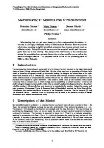
List of Figures Figure 3.1 Types of perturbations for a core of columnar vortex: 1-core boundary, 2-lines of fixed phase kz m const (from Alekseenko et al. [35]). ..... 29 Figure 4.1 Various modal basis functions on the interval
1,1 , for N 4 . ...... 38
Figure 4.2 Illustration of a one-dimensional collocation grid used to compute the disturbance profile. ..............................................................................44 Figure 5.1 The basis functions domain
r
on the clustered grid with
N 7
nodes, on
0,3 . ...................................................................................47
Figure 6.1 The basis of shifted Chebyshev functions
Tk*
on domain
0,3 . ..... 55
Figure 8.1 Spectra of the hydrodynamic eigenvalue problem computed at 0.01 , m 3 , a 0 , q 0.1 . .................................................. 79 Figure 8.2 Comparative absolute values of eigenfunction amplitudes of the most unstable mode 0.01 , m 3 , a 0 , q 0.1 . ............................. 81 Figure 8.3 Behavior of the eigenvalue problem residual as function of the spectral parameter N . ....................................................................................82 Figure 8.4 Radial distribution of velocity field for perturbed flow with nonaxisymmetric mode m 2 , a 0 , q 0.05 0.1 . ......................... 82 Figure 8.5 Absolute values of eigenfunction amplitudes .................................... 84 Figure 8.6 Residual of the eigenvalue problem and corresponding histogram. ...... 86 Figure 8.7 Spectra of the q-vortex hydrodynamic eigenvalue problem computed at parameters 0.01 , m 3 , a 0 , q 0.1 ................................... 87 Figure 8.8 Comparison of the absolute values of disturbances of the most unstable mode 0.01 , m 3 , a 0 , q 0.1 , without stabilization (a) and with lanczos stabilization (b). ....................................................................... 88 Figure 8.9 Comparison of the radial evolution of the disturbances of the most unstable mode m 1 , at 0.78 , a 1.268 , q 0.6 . ............... 89 Figure 8.10 Comparison of the radial evolution of the disturbances of the most unstable mode m 1 , at 0.2 , q 0.6 , a 0.01 . ...................... 90 Figure 8.11 Comparison of the radial evolution of the disturbances of the most unstable mode m 1 , at 0.0425 , q 0.7 , a 0 ......................... 90 Figure 9.1 Computer aided mathematics and numerical analysis laboratory of the Engineering Faculty of Hunedoara, “Politehnica” University of Timisoara. ..... 92 Figure 9.2 Scheme of cluster configuration. .................................................... 93 Figure 9.3 The model of helical vortex............................................................95 Figure 9.4 The flow chart of the vortex hydrodynamic stability algorithm............. 95 Figure 9.5 The axial velocity component for different discharge coefficients. ........ 97 Figure 9.6 The circumferential velocity component for different discharge coefficients. ........................................................................................97 Figure 9.7 Comparison of radial distribution
rG
corresponding to the eigenvalue
with the largest negative imaginary part in axisymmetric mode for discharge coefficient
m 0, 0 ,
0.36 . ....................................................... 98
Figure 9.8 Evolution of the radial disturbance
|G |
along the radial direction for
several increasing discharge coefficients. ................................................ 99 Figure 9.9 Evolution of the critical frequency as function of discharge coefficient for axisymmetric mode m 0 . ............................................................... 100 Figure 9.10 Evolution of the axial disturbance
|F |
on radial direction, for
m 1, 0 , for several discharge coefficients......... 101 Figure 9.11 Evolution of the radial disturbance | G | on radial direction, for investigated mode m 1, 0 , for several discharge coefficients......... 101 investigated mode
Figure 9.12 Distribution of the critical eigenvalues of the perturbed flow at several operating points, in bending modes spatial investigation. ........................ 102 Figure 9.13 Evolution of the critical frequency as function of discharge coefficient for mode m 1 .................................................................................. 103 Figure 9.14 Evolution of the critical frequency as function of discharge coefficient for mode m 1 . ................................................................................... 104 Figure 9.15 Axial and circumferential velocity profiles of the vortex rope model.. 105 Figure 9.16 Maximum growth rate as function of mode in spatial analysis and temporal analysis. ............................................................................. 106 Figure 9.17 Convective instability of the flow in hydraulic turbine draft tube after perturbing flow. the curves are extracted at several non-dimensional time units t 10,15,18,22,25 at the wall boundary. ........................................... 107 Figure 9.18 Fluctuating pressure as function of time, at the wall boundary, extracted at several locations on the draft tube: non-dimensional axial coordinates z 1.71,2.43,3.30, 4.12, 4.25 .......................................................... 107 Figure 9.19 Absolute instability of the flow in hydraulic turbine draft tube after perturbing flow. the curves are extracted at several non-dimensional time units t 10,15,18,22,25 at the wall boundary. ........................................... 108 Figure 9.20 Critical frequency as function of mode. the value of the critical frequency
cr 0.3
for modes
m 0,1
is the same as in the
experiments [110] and [111]. ............................................................. 109 Figure 9.21 Critical axial wavenumber as function of mode. the value of the critical wavenumber
kcr 3.2
for modes
m 0,1,2
is the same as in the
experiment [110]. ............................................................................. 110 Figure 9.22 Variation of perturbed pressure at mode m 0 . ......................... 111 Figure 9.23 Variation of perturbed pressure at mode
m 1 . .......................... 111
3 ....................................... 113 2 ....................................... 113 Figure 9.26 Dominant frequency for mode 1 ....................................... 114 0 ......................................... 114 Figure 9.27 Dominant frequency for mode Figure 9.28 Dominant frequency for mode 1 . ........................................ 114 2 ......................................... 114 Figure 9.29 Dominant frequency for mode Figure 9.30 Dominant frequency for mode 3 ......................................... 114 Figure 9.31 Residual along the optimum range for mode m 3 . .................. 115 Figure 9.24 Dominant frequency for mode
Figure 9.25 Dominant frequency for mode
m m m m m m m
Figure 9.32 Residual along the optimum range for mode Figure 9.33 Residual along the optimum range for mode Figure 9.34 Residual along the optimum range for mode Figure 9.35 Residual along the optimum range for mode Figure 9.36 Residual along the optimum range for mode Figure 9.37 Residual along the optimum range for mode
m m m m m m
2 ................... 115 1 ................... 115 0 ..................... 115 1 ...................... 116 2 ..................... 116 3 ..................... 116
Figure 9.38 Elapsed time for mode m 1 , on four cluster configurations. ...... 117 Figure 9.39 Parallel algorithm speedup as function of the number of parallel processors, computed for spectral parameter
N 83,61, 46 . .............. 119
Figure 9.40 Parallel algorithm efficiency as function of the number of parallel processors, computed for spectral parameter
N 83,61, 46 . .............. 119
List of Tables Table 2.1 A synthesis of the methods used in literature for flow stability investigations...................................................................................... 24 Table 3.1 Axis boundary equations comparison. .............................................. 31 Table 4.1 The function gridcheb.m generates the clustered grid. ....................... 43 Table 4.2 The function mapcheb.m for mapping the clustered grid onto the physical domain. .............................................................................................44 Table 4.3 The function polycheb.m generates the values of the nth shifted Chebyshev polynomial in the collocation nodes, by polynomial relation. ....... 45 Table 4.4 The function shiftrec.m generates the shifted Chebyshev polynomials by recurrence. .........................................................................................45 Table 5.1 Interpolative derivative matrix implementation.................................. 52 Table 6.1 The function policevs.m generates symbolically the polynomial defined on domain
n th
Chebyshev
0, rwall ................................................. 59
Table 6.2 Functions to generate symbolically the integrands.............................. 59 Table 6.3 Function integrala.m......................................................................61 Table 6.4 Sequence for construction of the evaluation matrices. ........................ 61 Table 7.1 Dynamic matrices and boundary condition implementation in temporal analysis for mode m 0 . ....................................................................71 Table 7.2 Dynamic matrices and boundary condition implementation in spatial analysis for mode m 0 . ....................................................................74
a 0 , q 0.1 , m 3 : eigenvalue with
Table 8.1 Comparative values of the most unstable mode at
0.01
for the case of the counter-rotating mode
largest imaginary part
kcr .................................................................... 80
Table 8.2 Convergence behavior of the critical eigenvalue for the most unstable mode m 3 with 0.01 , a 0 , q 0.1 . ................................... 81 Table 8.3 The most amplified axial wavenumber for various modes. ................... 81
Table 8.4 Comparative results of the most amplified spatial wave of the Batchelorvortex: eigenvalue with largest imaginary part
kcr kr , ki . .................. 83
Table 8.5 Comparison of the convergence behavior of the algorithm assessing radial
2
boundary adapted method and L -projection method. ............................. 85 Table 8.6 Comparative results of the most amplified spatial wave of the Batchelorvortex: eigenvalue with largest imaginary part
kcr kr , ki . .................. 87
Table 8.7 Numerical results comparison for bending modes investigation. ........... 89 Table 8.8 Comparative results of the most unstable spatial mode of the Batchelorvortex at a 0 , q 0.1 , 0.01 for the case of mode m 3 : eigenvalue with largest imaginary part
kcr kr , ki
and estimated numerical
error..................................................................................................91 Table 9.1 Swirl parameters for investigated turbine operating points: φ .............. 96 Table 9.2 Eigenvalues of the most unstable axisymmetric mode at several operating points. ...............................................................................................99 Table 9.3 The critical frequencies corresponding to axisymmetric mode m 0 at several operating points. .................................................................... 100 Table 9.4 Eigenvalues of the most unstable modes for bending modes investigation, at several operating points.................................................................. 102 Table 9.5 The critical frequencies corresponding to bending mode m 1 ....... 103
Table 9.6 The critical frequencies corresponding to bending mode m 1 . ........ 103 Table 9.7 The critical frequency and the maximum growth rates obtained for the investigated modes............................................................................ 106 Table 9.8 Convergence of the algorithm for the investigated mode numbers. ..... 113 Table 9.9 Elapsed time (in seconds) of numerical simulations for mode m 1 , in sequential processing and on four cluster configurations parallel processing118
1. Introduction 1.1 Motivation Renewable energy resources recently have become used in energy production of electrical energy. One of these resources is represented by the energy produced in hydropower plants. The possibility to store it and the fact that it has a relative simple production makes the hydro energy to become a preferred resource compared to other system of production. Production of energy at variable discharge coefficients makes that the turbines used in practice to be operated far from optimal exploit conditions. In particular, at part load operating conditions Francis turbine fixed-pitch runner shows a strong swirl at the runner outlet. As the incoming swirling flow is decelerating in the diffuser cone, a hydrodynamic instability arises under the form of a characteristic precession flow, named the vortex rope, see Jacob [1]. The vortex rope creates high-pressure unsteady fluctuations on the walls of the draft tube (Baya et al. [2]). These can lead to a poor performance of the turbine including fatigue damage (Frunzăverde et al. [3]). This phenomenon is especially severe when the frequency of the oscillations of the vortex rope matches the resonant frequency of the turbine or circuit. Modeling of the hydrodynamic phenomena which lead to vortex rope occurrence represent a complex task which requires to consider all the combinations which generate the instability in the fluid system. Experimental investigations of the conditions leading to vortex rope occurrence are difficult from technological point of view, requiring complex measurement systems (in case of laboratory investigation, Iliescu et al. [4]) which are not suited in the real systems evaluation. This makes that the mathematical modeling of the flow to become an important tool in the design of hydraulic system. The unsteady system must be dynamically analyzed which assumes solving the Navier-Stokes model for different sets of conditions enforced by the real characteristics of the flow. Due to the nonlinearity of the Navier-Stokes equations, the solution of the mathematical model requires a careful approach. Despite the latest progresses of the computational fluid dynamics (CFD) and in the computational resources respectively, modeling of turbulent flows remains a cumbersome task. The computational resources required by the software applications to accurately simulate the turbulent flows are huge, caused by several factors. These applications are mostly based on numerical methods like finite element or finite volume method. Beside the fact that these methods require a very fine mesh having a large number of nodes, methods based on finite element face difficulties also due to the instability of the real phenomenon. Finite element methods can lead to long computational time and parallel computational resources. In these conditions, stability analyses of swirling flow can help to better understand the dynamical behavior of the flow and offer an insight of the physical mechanics of the observed dynamics.
12 Introduction – 1 As an alternative to classical methods the present thesis proposes a new approach of the analysis of the swirling flows, based on a recently mathematical method of spectral collocation. The stability investigation of the swirling flows supposes few steps. The first step is the boundary conditions determination for the studied situation. A problem which was studied in this thesis is the quality of the solution depends on the boundary conditions imposed. Many surveys cited in literature consider the problem of simulating the flow downstream the hydropower runner, but there no exists so far investigations considering the swirling flow in hydropower turbine from the point of hydrodynamic stability analysis. This thesis intend to cover this gap and presents the methodology developed for spatial/temporal stability investigation of the swirl flow in Francis diffuser and the results obtained.
1.2 Literature Review Characterizations of the part load operating conditions in the Francis turbine have been carried out extensively by Susan-Resiga et al. in [5] and the technology for overcoming the draft tube surge through active control has been established. Thicke [6] reviews some optimum design rules for draft tubes, as well as some practical solutions for draft tube instability problems. McDonald et al. [7] provide basic design information for diffusers with incompressible swirling inlet flow. They show that swirling inlet flow does not affect the performance of diffusers which were no separated or only slightly separated with axial inlet flow. Resiga et al. [8] carried out an experimental and theoretical investigation of the flow at the outlet of a Francis turbine runner, in order to elucidate the causes of a sudden drop in the draft tube pressure recovery coefficient at a discharge near the best efficiency operating point. It was found that the investigated mean swirling flow can be accurately represented as a superposition of three distinct vortices. An eigenvalue analysis of the linearized equations for steady, axisymmetric and inviscid swirling flow revealed that the swirl reaches a critical state precisely (within 1.3%) at the discharge where the sudden variation in draft tube pressure recovery is observed. This is very useful for turbine design and optimization, where a suitable runner geometry should avoid such critical swirl configuration within the normal operating range. The availability of advanced optical instrumentation, such as laser Doppler velocimetry (LDV) or particle image velocimetry (PIV) systems, gives the opportunity to perform flow surveys in turbo machinery and in particular to investigate the unsteady characteristics of the complex flow velocity fields in the case of, for instance, the rotor-stator interactions, the draft tube, or the spiral casing. The progress of the numerical techniques in the prediction of the turbine characteristics for the operating ranges in the vicinity of the best efficiency point (BEP) insure a good accuracy, see Vu et al. [9]. The massively parallel computations development permits now the numerical simulation of the whole turbine, see Ruprecht et al. [10], or to detail the flow in a specific part of the turbine. One of the new challenges for the numerical turbine simulation is to predict the partial or full flow rate operating regimes and the first simulations are promising. Ruprecht et al. [11] are focused on the influence of different turbulence models on the modeling of the draft tube vortex, carried out in a straight daft tube
1.2 – Literature Review 13
as well as in a real draft tube. Based on the length of the predicted vortex structure, certain turbulence models tend to have a damping effect and from this point of view, the most accurate is found to be a two-scale model, reduced to a two equations set by a Very Large Eddy Simulation (VLES) approach. An overview of unsteady simulations in hydraulic machineries is presented in [12]. Problems with self-excited unsteadiness, vortex rope in the draft tube, applications with externally forced unsteadiness and rotor-stator interactions are solved using a finite element code. The pressure is calculated by a pressure correction algorithm. The time discretization is obtained by a fully implicit 3-level scheme of 2nd order and the spatial discretization is done by using bi-linear 8-node brick elements. For the solution of the linear equation systems a conjugated gradient method is used for non-symmetrical matrices. Scherer et al. [13] reported the turbine design improvement for the draft tube operating at partial flow rate conditions by Computational Fluid Dynamics (CFD). An unsteady one-phase Reynold’s Averaged Navier-Stokes (RANS) simulation of the draft tube vortex in a Francis turbine model is used to compare two draft tube configurations. By comparing the calculated performances of two model machines over the operating range, the second one is found to have better draft tube efficiency at low flow rate operation, justified by the obtained pressure pulsations improvement, the diminishing of the strong velocity gradients, and backflow zone in the cone. The comparison with wall pressure experimental data shows a good agreement for the vortex frequency and a systematic underestimation of the pressure fluctuation amplitudes. Miyagawa et al. [14] performed an unsteady simulation of the draft tube vortex for a Francis pump turbine, consecutively for two different runners. The purpose was to analyze the influence of the velocity profile at the runner outlet on the flow instability in the draft tube. Two runner designs are tested for the same draft tube geometry using a mesh of 620.000 nodes. The same vortex behavior changes are observed in CFD and experimentally by qualitative comparisons with the rope visualizations. The authors tested a one phase and a two-phase model as well, and found that it influences mainly the fluctuation amplitude and has no influence on the vortex frequency, but no further details are given. A numerical study of the real flow through a Francis turbine having a high/medium specific speed was carried out by Magnoli [15], to predict the pressure pulsations induced by the interaction between rotor and stator. The numerical model reproduce as accurately as possible the model behavior at the test rig. Numerous numerical schemes and parameters were tested and verified with the available experimental results. Recently, the influence of turbine location on the flow system stability has been studied by Alligne et al. [16]. The hydro-acoustic models of hydraulic components have been made based on electrical equivalent schemes. An eigenanalysis tool, based on eigenvalues and eigenvectors computation of the nonlinear set of differential equations modeling the hydrodynamic system has been developed. An example of experimental investigation is carried out in paper [17] focusing on vortex rope breakdown on a high specific speed Francis turbine scale model. Observations of the cavitation vortex carried out with high speed camera have been recorded and synchronized with pressure fluctuations measurements at the draft tube cone.
14 Introduction – 1
1.3 Thesis Objectives The main objectives of this thesis are the modeling of the swirling flows hydrodynamic instability assessing both analytically mathematical methods and development of numerical algorithms to investigate the spatial/temporal stability of the swirling flows systems. These instruments may offer information concerning the parameters that produce the hydrodynamic instability, which may lead to the optimization of flow control problems. Sophisticated mathematical calculations are needed to analytically modeling the swirling flows and we have no information concerning the software application for hydrodynamic stability investigation of the vortex structures. The numerical stability algorithms developed and presented in this thesis allow the sensing of the hydrodynamic instability states for characteristic parameters sets, in the process of understanding of the real fluid flow dynamic. Selection of the spectral methods as a tool for solving the eigenvalue problems governing the flow hydrodynamic stability is motivated by the accuracy of these methods and the exponentially decreasing of the error, differently form the finite element methods having an algebraic convergence rate. A major benefit of collocation based method is given by a fast processing time and available hardware resources. The spectral algorithms presented in this thesis have been validated with existing stability investigations concerning the swirling flow system with known velocity profiles, namely the Batchelor vortex problem and applied for the investigation of practical problems based on experimental test measured parameters of fluid flow in Francis turbine draft tube. The originality of the new spectral algorithms developed in this thesis consists in: Rebuilt of the mathematical model governing the swirling flow with differential operators; Development of a special orthogonal test functions defined directly on the physical space of the practical problem, increasing the solution accuracy; Recasting of the unknown eigenvectors in series of orthogonal expansions by means of boundary adapted test functions, satisfying the boundary conditions, this technique allowing to eliminate the axis singularities; Approximation of derivatives of the unknown eigenvectors by means of spectral differentiation matrices, particularly derived in different flow problems; Determination of an optimal clustered grid; Optimal implementation of the Dirichlet, Neumann and mixed boundary conditions; Inclusion of some efficient numerical libraries with eigensolvers in the software platform. The environment for algorithms development and test was Matlab, due to the very advanced mathematical embedded functions, allowing the user to focus on developing algorithms instead of the details of the implementation. It is not possible to consider advanced computational algorithms without including the parallel and distributed processing. In this thesis, the numerical algorithms developed were further improved by means of parallel and distributed processing on a cluster structure.
1.4 – Dissertation Outline 15
1.4 Dissertation Outline This thesis is outlined as follows: Chapter 1 gives a motivation for the study of hydrodynamic stability of the swirling flow in Francis hydropower turbine using computer aided techniques of parallel and distributed computation. Chapter 2 gives an overview of the linear stability analysis of vortex hydrodynamics. The mathematical model of the swirling flow downstream the Francis turbine runner is developed in Chapter 3. Chapter 4 presents theoretical considerations about the spectral methods used in forthcoming numerical stability algorithms. Computational approaches for stability eigenvalue problems are presented here and a new orthogonal base of polynomial test functions is introduced. A boundary adapted radial spectral approximation for non-axisymmetric stability investigation is presented in Chapter 5. A modified L2 -projection method based on shifted polynomials for axisymmetric and bending modes stability investigation is presented in Chapter 6. A parallel computation method based on spectral descriptor technique for analysis of swirling flows hydrodynamic stability with sophisticated boundary conditions is presented in Chapter 7. In Chapter 8 validation of the numerical procedures on a Batchelor vortex problem is assessed. Chapter 9 presents the results of parallel and distributed investigation of the vortex rope model using Matlab Distributed Computing Server on a Windows operating system cluster. This thesis ends in Chapter 10 where conclusions and future work are outlined.
2. MATHEMATICAL ISSUES ON STABILITY OF SWIRLING HYDRODYNAMIC SYSTEMS 2.1 Linearized Disturbance Equations The role of the hydrodynamic stability theory in fluid mechanics reach a special attention, especially when researchers deal with problem of minimum consumption of energy. This theory deserves special mention in many engineering fields, such as the aerodynamics of profiles in supersonic regime, the construction of automation elements by fluid jets and the technique of emulsions. The field of hydrodynamic stability has a long history, going back to Reynolds and Lord Rayleigh in the late 19th century. Since then, its central role in many research efforts involving fluid flow resulted in a huge number of studies. The main interest in recent decades is to use the theory of hydrodynamic stability in predicting transitions between laminar and turbulent configurations for a given flow field. R.E. Langer [18] proposed a theoretical model for transition based on supercritical branching of the solutions of the Navier-Stokes equations. This model was substantiated mathematically by E. Hopf [19] for systems of nonlinear equations close to Navier-Stokes equations. C.C. Lin, a famous specialist in hydrodynamic stability theory, published his first paper on stability of fluid systems in which the mathematical formulation of the problems was essentially different from the conservative treatment [20]. The intermittent character of the transition of motions in pipes was identified for the first time by J.C. Rotta [21]. J.T. Stuart in [22] developed an energetic method frequently used in the investigation of transition, method that was undertaken by D.D. Joseph whose intensive activity has lead to the theory of the global stability of fluid flows [23]. The Nobel laureate Chandrasekhar [24] presents in his study considerations of typical problems in hydrodynamic and hydro magnetic stability as a branch of experimental physics. Among the subjects treated are thermal instability of a layer of fluid heated from below, the Benard problem, stability of Couette flow, and the Kelvin-Helmholtz instability. The access to computers at an institutional and personal level has defined a new era in teaching and learning. The opportunity to extend the subject of hydrodynamic stability from the matter of traditional science and engineering disciplines into the realm of scientific computing has become not only desirable, but also necessary. The new environment has motivated the writing of texts and monographs with a modern perspective that incorporates numerical and computer programming aspects. In a beautiful monograph C. Pozrikidis [25] offer an introductory course in fluid mechanics, covering the traditional topics in a way that unifies theory, computation, computer programming and numerical simulation. Canuto et al. [26] introduce the main strategies for constructing numerical spectral approximations in complex domains, in particular, the spectral element method, the mortar element method, the spectral discontinuous Galerkin method, as well as the more traditional patching collocation method. Recently, new techniques to numerically solve all kinds of ordinary and partial differential equations connected with problems in fluid dynamics, quantum mechanics, vibrations, linear and
2.1 – Linearized Disturbance Equations 17
nonlinear waves and other fields were developed. The aim of the book of L. Trefethen [27] is to present the essentials of spectral collocation methods with the aids of a computer algebra system, presenting advanced numerical algorithms and solutions of nontrivial problems. Many publications in the field of hydrodynamics are focused on vortex motion as one of the basic states of a flowing continuum and effects that vortex can produce. Such problems may be of interest in the field of aerodynamics, where vortices trail on the tip of each wing of the airplane and stability analyses are needed and to study the hydrodynamics of rotating machines where confined vortices are developed due to the turbine rotation. Mayer [28] and Khorrami [29] have mapped out the stability of Q-vortices, identifying both inviscid and viscous modes of instability and studies of Leibovich et al. [30], Orszag [31], Parras et al. [32], Payne et al. [33], Reddy et al. [34] have examined the stability of vortex cores with axial velocities component. Hydrodynamic stability theory is concerned with the response of a laminar flow to a disturbance of small or moderate amplitude. If the flow returns to its original laminar state one defines the flow as stable, whereas if the disturbance grows and causes the laminar flow to change into a different state, one defines the flow as unstable. Instabilities often result in turbulent fluid motion, but they may also take the flow into a different laminar, usually more complicated state. Stability theory deals with the mathematical analysis of the evolution of disturbances superposed on a laminar base flow. In many cases one assumes the disturbances to be small so that further simplifications can be justified. In particular, a linear equation governing the evolution of disturbances is desirable. As the disturbance velocities grow above a few percent of the base flow, nonlinear effects become important and the linear equations no longer accurately predict the disturbance evolution. Although the linear equations have a limited region of validity they are important in detecting physical growth mechanisms and identifying dominant disturbance types. In this chapter we will derive the nonlinear equations, governing the development of a disturbance on a laminar base flow, define various types of stability and discuss some general concepts and results. The equations governing the general evolution of fluid flow are known as the Navier-Stokes equations. They describe the conservation of mass and momentum. The radial and axial coordinates and also the time scale for the system equation governing the flow were considered normalized by a reference dimension and they are nondimensionalized, i.e. z where Lref
z* , Lref
r
r* , Lref
t
t* Uc , Lref
(2.1)
represents a characteristic length scale of the problem that will be
defined for specific cases as the analysis proceeds, Uc represents a characteristic flow velocity of the problem and superscript * denotes a dimensional quantity. To nondimensionalize the velocity field and pressure, we introduce the following scaling uz
u*z , Uc
ur
ur* , Uc
u* u , Uc
p
p*
U c
2
(2.2)
For an incompressible fluid, in terms of these normalizing variables using Cylindrical coordinates z, r , , the Navier-Stokes equations read
18 Mathematical Issues on Stability of Swirling Hydrodynamic Systems – 2 1 1 u uz 0, rur r r r z uz 1 p u uz uz , t z Re
(2.3) (2.4)
u2 ur ur 1 2 u p u ur ur 2 2 , r t r Re r r u uu u 1 p 1 2 ur u u r u 2 2 , t r r Re r r
where
u uz , ur , u
(2.5) (2.6)
is the velocity vector of axial, radial and tangential
components, 1 1 2 2 (2.7) r 2 r r r 2 2 z 2 is the Laplace operator, the function p is the fluctuating pressure, Re represents the Reynolds number and u (2.8) uz u ur r r z The coordinates z , r , and the time t are independent variables and the functions uz , ur , u , p z, r , , t are the dependent variables. Equations (2.4), (2.5)
2
and (2.6) are nonlinear, making the solution of the system nontrivial. As a result, theoretical assumptions and simplifications are made to reduce the nonlinear partial differential equations to solving a problem of either linear partial differential equations or linear ordinary differential equations. To derive the equations that control the small oscillations the parallel and steady mean flow assumptions are made. By parallel flow we mean that the dependent variables for the base flow are at most function of only one independent variable, while steady denotes that the mean flow does not change with time. This derivation is done in three steps: separation of fluctuations, linearization and solve the system for complex functions applying the method of normal modes. Since we are considering the class of stationary basic states, we assume that the flow can be decomposed into a laminar basic state U U, 0, W , p ' and a fluctuating component that oscillates about the basic flow the fluctuation being of order 0 1 uz z, r , , t U(r ) v z z, r , , t ,
V v z , vr , v , ,
with
(2.9)
ur z, r , , t vr z, r , , t ,
(2.10)
u z, r , , t W(r ) v z, r , , t ,
(2.11)
p z, r , , t p '(r ) z, r , , t .
(2.12)
Consistent with the parallel mean flow assumption is that the functional form for the mean part of the velocity components only involves the cross-stream coordinate r and also zero mean radial velocity. Expressing each flow quantity in the form of (2.9)-(2.12) and substituting these expressions into equations (2.3)-(2.6), gives v v 1 (2.13) r r W v U v z 0, r r r z
2.1 – Linearized Disturbance Equations 19
W v U v z vr U v z U v z t r r 1 U v z U v z p ' U v z Re z z v v W v vr U v vr r 2vr r z t r r z
W v 2
v 1 2 p ' vr 2r 2 W v , Re r r r r W v W v vr W v W v r t r v W v 1 U v z W v r p ' r r z W v 1 2 vr 2 W v Re r2 r The basic-state quantities
U U, 0,W , p '
(2.14)
(2.15)
(2.16)
are always solutions of the
Navier-Stokes equations by themselves so equations (2.13)-(2.16) can be separated into disturbance-state equations and basic-state equations. The linearized disturbance equations are obtained after considering contributions of first order in delta. Basic state equations: 1 W U 0, r z U p ' 1 U U U 0, t z Re
W 2 p ' 1 2 W 0, r r Re r 2
W 1 p ' 1 W U W W 2 0 t r Re r
(2.17) (2.18) (2.19) (2.20)
where U
W U z r
Linearized disturbance equations: v r v r 1 v v z 0, r z r r v z v U v U W v z U 1 vr U z vz v z 0, r r t r z z z Re Wv vr W vr v vr 1 2 v U r 2 vr 2 2 0, t z r Re r r r r v v W W v v W W vr U vz t r r r z z v v W 1 1 2 vr r v 2 2 0 r r Re r r
(2.21)
(2.22) (2.23) (2.24)
(2.25)
20 Mathematical Issues on Stability of Swirling Hydrodynamic Systems – 2 The linearized Navier-Stokes equations are derived also in Alekseenko et al. [35] and in Drazin and Reid [36] and presented in a system equations form. For the stability studies concerning Francis turbine the fluid element being water the analysis can be simplified on the basis of hypothesis that viscosity can be neglected. In this case, for high Reynolds numbers as 105 106 for the flow in Francis hydraulic turbine, respectively 107 108 for the flow in the Francis turbine prototype, the linearized Euler equations are used instead of Navier-Stokes. The Euler basic state equations are the following: 1 W U (2.26) 0, r z U p ' (2.27) U U 0, t z
W 2 p ' 0, r r W 1 p ' U W 0 r t
(2.28) (2.29)
where U
W U r z
(2.30)
The linearized Euler disturbance equations are presented in the following: vr vr 1 v v z (2.31) 0, r z r r v z v U v U W v z U (2.32) vr U z vz 0, r r t r z z z Wv vr W vr v (2.33) U r 2 0, r r t z r v v W W v v W W vrW 1 (2.34) vr U vz 0 t r r r z z r r
2.2 The Method of Normal Modes Analysis The normal mode method is synthesized by Criminale et al. in a remarkable treatise [37] devoted to the subject of stability of fluid motion. Robert Blevins used this method in vibration analysis which is presented as an important part of design [38]. He provided a range of the natural frequencies and mode shapes of several practical important structural and fluid systems. Dynamic characteristics of most natural structures as fluids, heat transfer and control are the subject of the book of Tzou and Bergman [39], which aims to document recent progress on the subject and to bring the technical applications of the normal modes analysis to the engineering community. The main advantage of linear stability analysis is that we can seek solutions in term of complex functions and reduce the system of partial differential equations to ordinary differential equations. This particular approach of using complex quantities is called the normal mode approach and the solutions are called normal modes.
2.2 – The Method of Normal Modes Analysis 21
The factorization with respect to the axial coordinate z is allowed by the assumption on an axisymmetric parallel flow in a cylindrical pipe, so we shape the normal mode solution in form eikz (2.35) where k is the complex axial wavenumber. The factorization in the tangential direction can be considered based on the angular periodicity flow assumption, so we shape the normal mode solution in form eim (2.36) where m is the tangential integer wavenumber. A linear stability study implies linearized infinitesimal type perturbations so a factorization in time can be considered, of form eit (2.37) where represents the complex frequency. The disturbance components of velocity are shaped into normal mode solutions of the type
v z, r , , t Real iG r e v z, r , , t Real H r e z, r , , t Real P r e
, , ,
i kz m t v z z, r , , t Real F r e , r
i kz m t
i kz m t
i kz m t
(2.38)
where F , G, H, P represent the complex normal mode forms of the amplitudes of the perturbations. Introducing the factorization form (2.38) into the linearized Euler disturbance equations (2.31)-(2.34) we obtain the following set of first order differential equations (ODE) with variable coefficients G r H r m kF r 0 , (2.39) dr G r r r W r 2W r H r kU r G r dr P r 0 , m r r
(2.40)
W r W r P r kU r H r drW r 0 ,(2.41) m G r m r r r W r kU r F r G r dr U r kP r 0 , m r where dr means differentiation with respect to the radius.
(2.42)
The system of first order differential equations (2.39)-(2.42) governs the stability of the fluid system. The unknown functions hydrodynamic F r , G r , H r , P r depending on radial coordinate must be found solving the system and represent the disturbance amplitudes. A hydrodynamic model for a viscous swirling flow was derived in [40].
22 Mathematical Issues on Stability of Swirling Hydrodynamic Systems – 2
2.3 Definition of Temporal and Spatial Instability The fact that many problems involving swirling flows motion can be cast in the formulation of vortex dynamics has stimulated much interest. Vortex dynamics is a frequent meet situation in fluid flow as modern dynamical system theory must include also turbulence and vortex studies. The fundamental properties of vorticity and a review of the classical theory of inviscid incompressible fluids containing finite regions of vorticity are emphasized in the monograph of Saffman [41]. Wu et al. [42] present fundamental processes in fluid motion and a description of the vortex evolution following its entire life. A review of recent developments in the hydrodynamic stability theory of spatially developing flows pertaining to absolute/convective and local/global instability concepts is presented in a beautiful synthesis in Huerre and Monkewitz [43]. The use of the normal mode relationship for perturbations (2.38) substituted into the linearized system (2.31)-(2.34) transforms the partial differential equations into ordinary differential system (2.39)-(2.42), where the complex eigenfunctions F , G , H and P are unknown functions of r . The complex frequency r ii and the complex wavenumber kr iki introduce four additional unknowns, resulting in more unknowns than equations. Hence, in order to obtain the solutions, we must make assumptions concerning these unknowns. When the complex frequency r i i , r Re() , i Im( ) is determined as a function of the real wavenumber k a temporal or absolute stability analysis is performed. The disturbance is applied in space by the fixed wavenumber k and is observed as it evolves in time through the complex frequency calculated as the eigenvalue. The eigenvalue problem governing the flow stability is expressed as (2.43) f k , m, R , where f is a complex map. Equation (2.43) yields a r , i pair when k , m, and R (denoting some other parameters of the system) are specified. In this case, the local normal mode is still given by (2.38), and when we decompose the amplitude F Fr iFi and temporal frequency r ii , one sees how the real and imaginary part of F and contributes to the wave solution
ei t Fr cos r t Fi sin r t cos Fi cos r t Fr sin r t sin , kz m . (2.44) The temporal growth rate is given by i for obvious reasons. Thus disturbances can be grouped into three classes depending on the sign of i , namely,
i 0 : amplified disturbances; absolute unstable flow,
(2.45)
i 0 : no change in time; neutral,
(2.46)
i 0 : damped disturbances; stable flow.
(2.47)
Conversely, solving the ODE system (2.39)-(2.42) for the complex wavenumber k kr i ki , kr Re(k ) , ki Im(k ) , when is given real leads to
the spatial branches k(, ) where by we denoted the set of all other physical parameters involved. The disturbance is applied in time, with real frequency and the evolution of the perturbation is observed in space.
2.4 – Studies Upon Stability of Swirling Flows Cited in Literature 23
The eigenvalue problem of system (2.39)-(2.42) is expressed as k f , m, R ,
(2.48)
where f is a complex map. Equation (2.48) yields a kr , ki pair when , m, and R (denoting some other parameters of the system) are specified. The spatial growth rate of the wave solution in spatial case depends on the imaginary part of the axial wavenumber k, as described in the next formula e ki z
Fr cos kr z Fi sin kr z i Fr sin kr z Fi cos kr z ,
m t. (2.49) Thus disturbances can be grouped into three classes depending on the sign of ki ,
namely, ki 0 : amplified disturbances; convective unstable flow,
(2.50)
ki 0 : no change in time; neutral,
(2.51)
ki 0 : damped disturbances; stable flow.
(2.52)
2.4 Studies Upon Stability of Swirling Flows Cited in Literature Flows with swirling motions are subject of major changes in their dynamics, involving very large disturbances when a characteristic ratio of tangential to axial velocity components is varied. The results of the theoretical analysis of the stability of swirling fluid systems are widely present in literature. A synthesis of the methods used for flow stability investigations in some cited references is presented in Table 2.1. The linear versus nonlinear convective/absolute instability properties of a Batchelor vortex are investigated by Delbende et al. in [44] using the method of direct numerical simulation of the linear impulse response. The results of this numerical procedure were in good qualitative and quantitative agreement with those obtained by direct application of the Briggs-Bers criterion to the inviscid dispersion relation used in Olendraru et al. [45]. The characteristics of absolute/convective instability of a few families of swirling jets, examined with analytical and numerical tools, referred to the Batchelor vortex as a continuous basic flow whose velocity field is represented within trailing line vortices. The main objective of the study of Olendraru et al. [46] was to examine the spatial/temporal instability properties of the Batchelor q-vortex, as a function of swirl ratio and external axial flow parameter. For a set of a given values of the vortex parameters, the spatial branches were numerically determined as a function of the complex frequency by making use of a shooting algorithm. The results of the investigation presented in this paper may also be compared with the inviscid instability analysis of the Rankine vortex with axial flow performed by Loiseleux et al. [47]. In [47] a study of the absolute/convective instability transition curves pertaining to all helical modes has been conducted for both jets and wakes and for both centrifugally destabilizing and stabilizing swirl distributions. The paper focuses on systematically determine the absolute/convective instability boundary of the basic flow by locating the absolute/convective transition curves of all positive and negative helical modes. The results very significantly extend those obtained by Lim and Redekopp [48]. The characteristics of absolute/convective instability of two
24 Mathematical Issues on Stability of Swirling Hydrodynamic Systems – 2
idealized models of swirling flows that are centrifugally destabilized have been analyzed in [48]. A modified Rankine vortex model with superimposed axial flow is allowed to exhibit a centrifugally destabilizing tangential velocity discontinuity. The increasing magnitude of the discontinuity is then shown to very significantly enhance the absolute growth rate of the axisymmetric mode. The stability of weakly compressible three-dimensional jets and their transition to turbulence was studied by Rudman et al. [49]. Here the naturally growing of the most unstable mode was obtained by adding a small white noise (random) perturbation to each component of the base jet velocity profile. The numerical method used here for temporal simulations is based on the piecewise parabolic method [50] combined with time-splitting of an additional diffusive term. The linear stability theory and the finite difference technique were utilized by Guohui et al. [51] to study the dynamics of a swirling jet. The temporal instability and nonlinear evolution of the swirling jet near a nozzle exit were studied by both normal-mode method and three dimensional direct numerical simulation method. The early stage numerical simulations showed that the results were well consistent with the prediction of the linear stability theory. A key point in stability analysis is solving the eigenvalue problem that governs the hydrodynamic stability of the flow and practical difficulties can arise. The shooting technique requires a good initial guess of the eigenvalue and only a single eigenvalue is tracked. Another possibility is to make use of the compound matrix method as discussed by Anturkar et al. [52], Ng and Reid [53, 54], Yiantsios and Higgins [55], for solving difficult eigenvalue problems. Although this method is in general superior to shooting techniques [46, 47], neither this method does not provide the overall picture of the eigenvalue spectrum. Table 2.1 A synthesis of the methods used in literature for flow stability investigations. Reference Delbende, Chomaz and Huerre [44] Olendraru, Sellier, Rossi and Huerre [45, 46] Loiseleux, Delbende, Huerre [47] Lim and Redekopp [48] Rudman, Gathmann, Lesieur [49] Guohui, Dejun, Xieyuan [51] Anturkar, Papanastasiou, Wilkes [52], Ng and Reid [53, 54], Yiantsios and Higgins [55] Mehdi R. Khorrami [56], Su and Khomami [57], Boomkamp, Boersma, Miesen, Beijnon [58]
Method of investigation direct numerical simulation of the linear impulse response shooting numerical algorithm implemented by making use of IMSL routines analytical investigation of the dispersion relation analytical investigation of idealized flow models piecewise parabolic method normal mode method and three dimensional direct numerical simulation compound matrix method spectral collocation technique
2.4 – Studies Upon Stability of Swirling Flows Cited in Literature 25
Building upon the paper by Mehdi R. Khorrami [56] and Su and Khomami [57], Boomkamp et al. [58] solve the eigenvalue problem by means of a Chebyshev collocation technique, which takes away the difficulties mentioned before. The spectral method has the convenient property that it converges exponentially unlike other types of approximations and become widely used in computational hydrodynamic stability problems.
3. MATHEMATICAL MODEL OF SWIRLING FLOW DOWNSTREAM A FRANCIS TURBINE RUNNER 3.1 Discrete Operator Formulation of the Hydrodynamic Model In practical engineering problems such as control of high-Reynolds number flow, stability analyses are needed to predict vortex motion and effects that vortices can produce. J.M. Burgers [59] in 1948 first studied the stability of a new three-dimensional vortices class, taking his name. A later note was made by Darren G. Crowdy [60], on the linear stability of Burgers vortex, giving an analytical perturbative solutions for disturbances for small Reynolds numbers, letting open the unsolved problem of the linear stability of Burgers vortex to axially varying disturbances. The investigations concerned the values of parameters for which the vortex become unstable may imply a large amount of measurement, thus one must resort to numerical techniques. The present section is focused on developing the mathematical model leading to the eigenvalue problem governing the linear stability of the inviscid swirling fluid flow under small perturbations, downstream the Francis runner. Due to the lack of spectral theory with respect to non-selfadjoint differential operators this type of problems are far from being solved. We assume the swirling flow downstream the Francis runner as a steady columnar vortex whose velocity and pressure profiles are written as
U U r , 0,W r , p ' r ,
(3.1)
where U represents the axial velocity component, the radial velocity component is negligible and W is the tangential component of the velocity, all depending only on radius. This assumption is validated in the daft tube throat of Francis turbine, by Muntean PhD Thesis [61], Resiga et al. [62]. Introducing the factorization form (2.38) discussed earlier, into the linearized Euler disturbance equations (2.31)-(2.34) we obtain the mathematical model of the swirling flow system G r H r m kF r 0 , dr G r (3.2) r r W r 2W r H r kU r G r dr P r 0 , m r r
(3.3)
W r W r P r kU r H r drW r 0, m G r m r r r
(3.4)
W r kU r F r G r dr U r kP r 0 , m r
(3.5)
3.1 – Discrete Operator Formulation of the Hydrodynamic Model 27
d means differentiation with respect to the radius and the unknown dr functions F , G, H, P represent the disturbance amplitudes. The system (3.2)-(3.5) represents an eigenvalue problem with variable coefficients that governs the hydrodynamic stability of the fluid system. To handle this eigenvalue problem in the system formulation is difficult due to the presence of the derivatives of the unknown functions dr G, dr P . In this case, for a better where dr
manipulation in the process of deriving the numerical algorithm for stability analysis we write the mathematical model in descriptor notation (or operator formulation). Descriptor notation [65] is widely used in the control theory community to describe and analyze systems of differential-algebraic equations. In descriptor formulation of the ODE system governing the stability of the flow, the differential spatial operator dr is preceded by a square, possibly singular matrix
dr D I ,
where D I is the differentiation matrix operator [26, 27] and represents the modal collocated values of the unknown functions. The eigenvalue problem governing the hydrodynamic stability of the flow system is written in operator formulation as follows h 0,
h F
T
G H P
where the matrix operator is defined as 1 r 11 k , 12 D , 13 r mW 21 0, 22 kU, 23 r W 31 0, 32 W ' , 33 r mW 41 kU, 42 U ', r where prime represents
' the
(3.6)
m , 14 0, r 2W r , 24 D , r mW m kU, 34 , r r
43 0,
44 k ,
denotes derivative of the known velocity coefficients and radial
A r F , iG, H, P r
differentiation
and
a
operator,
i.e.
r dr A D a ,
(3.7) (3.8) (3.9) (3.10) r D
where
represents the modal collocated values of the
amplitudes. To obtain the system (3.2)-(3.5) imply a large analytically calculations when we handle with the Euler equations in system formulation, during the procedure of normal modes analysis aforementioned. We present hereinafter a second way to obtain the hydrodynamic stability model of the flow, by performing the calculations in descriptor notations only. We first put the linearized Euler disturbance equations (2.31)-(2.34) into operator formulation Ls 0,
s v z v r
v
T
where the elements of matrix operator L are 1 1 L11 z , L12 r , L13 , L14 0, r r W U U 1 U , L22 , L23 , L24 z , L21 t U z r r z r
(3.11) (3.12) (3.13)
28 Mathematical Model of Swirling Flow Downstream a Francis Turbine Runner – 3 W W (3.14) U z , L33 2 , L34 r , r r W W W W 1 W 1 , L42 , L43 t L41 U z , L44 , (3.15) r r r r z r when t , z , r , denote the partial derivative operators. L31 0,
L32 t
We substitute the partial derivatives operators as t i, z ik , im,
(3.16)
and the factorization form (2.38) in (3.11) leading to matrix relation 1 1 r ik im 0 r r W F i im Uik U ik ' 0 iG i kz m t r 0 e W W H i im Uik 0 2 r r r P W W 1 W ' im Uik im 0 i r r r (3.17) which is equivalent with m 1 r k 0 r r W F U' k 0 r m Uk G (3.18) 0. W W H m Uk 0 2 r P r r W W m W ' m Uk 0 r r r One can observe that the matrix equation (3.18) is equivalent with (3.6), representing the hydrodynamic stability relation of the flow system.
3.2 Axis and Wall Boundary Conditions Numerous stability studies led to the conclusion that many kinds of swirling flows, either bounded or free, exhibit instability. Before we begin the computational analysis of the instability problem, we will describe below the main types of axisymmetric and non-axisymmetric perturbations of a columnar vortex with a distinguish core of radius R , as presented in Alekseenko et al. [35]. The main types of disturbances affecting the core boundary, given by formula r R a cos kz m (3.19) are shown in Fig. 3.1 Amplitude is a R , k is the axial wavenumber, m is the integer tangential wavenumber, is the tangential angle and is the frequency. For analysis of disturbed core shape, the case when k is real and t 0 is considered.
3.2 – Axis and Wall Boundary Conditions 29
The case of m 0 corresponds to the axisymmetric mode. The wavelength has the value 2 / k and the cross-section z const are concentric circles with a radius from R a to R a . For m 0 we obtain non-axisymmetric modes. The modes with m 1 are usually called bending modes. The core cross-section z const is a circle of radius R , shifted by a distance a along the radius r at the angle kz / m . The mode m 1 takes the form of a left-handed helix and m 1 of a right-handed one. For m 2 the circular shape of the core cross-section transforms into an ellipse. For all the cases with m 2 , the vortex axis remains undisturbed, due to the symmetry in disturbance. If the amplitude of the disturbance is not small, we cannot use the simple canonic form. For the limiting case of an infinitely thin vortex filament, the disturbed state can be described by one of the canonic curves, a helical line r const , kz m const .
Fig. 3.1 Types of perturbations for a core of columnar vortex: 1-core boundary, 2-lines of fixed phase kz m const (from Alekseenko et al. [35]).
To complete the flow equation system, appropriate boundary conditions must be satisfied for an accurate simulation of the flow behavior. These conditions are obtained from discretization issues and physical requirements. For our stability investigation of the fluid system, the boundary conditions must be specified in the axis and to the wall boundary. The axial singularities in a cylindrical polar coordinates system occur due to the presence of terms 1/r, r-radial distance and because certain boundary conditions must be specified in r 0 . The axis boundary conditions that complete the homogenous first order differential system (3.2) to (3.5) are detailed in Batchelor and Gill [64]. In the following, we will make a review of the derivation of the boundary equations in axis origin.
30 Mathematical Model of Swirling Flow Downstream a Francis Turbine Runner – 3 While the axis is not a physical boundary, it is both a computational boundary and a singular line of the form of system equations being solved. The boundary condition is necessary to ensure that physically realistic solutions are obtained. In the axisymmetric case, if the radial and tangential velocities do not vanish at r 0 , then a vortex line must exist on the axis. Cylindrical coordinates may be converted into Cartesian coordinates by relations er cos i sin j (3.20) e sin i cos j ez k where er , e , ez and i, j, k are the local unit vectors at a point in cylindrical,
respectively Cartesian system. Hence results der d sin i cos j e de cos i sin j er d dez 0 d
(3.21)
Representing the perturbation velocity field by V v z , vr , v the flow is
independent of and this tidies up to V lim 0 and lim 0. r 0 r 0 We further have V lim lim v z ez vr er v e r 0 r 0 v e e v e v lim z ez v z z r er vr r e v r 0
(3.22)
v v v (3.23) lim z ez r v er vr e . r 0 The derivatives of the velocity field with respect to are expressed as v z vr v i kz m t , , F (r ), iG(r ), H(r ) e i kz m t imF , mG, imH e .
(3.24)
The relation (3.23) becomes V (3.25) lim lim imF ez Gm H er iG imH e 0 , r 0 r 0 and the last condition is (3.26) lim imP 0 . r 0 In order for these equalities to hold, each component of the resultant vector must be zero. Summarizing, we have mG H 0 , G mH 0 , mF 0 , mP 0 (3.27)
3.2 – Axis and Wall Boundary Conditions 31
in the center of the axis.
H 0 0 m 0 G 0 0 F 0 , P 0
;
(3.28)
finite
H 0 G 0 0 ; m 1 F 0 0 P 0 0
(3.29)
H 0 G 0 0 ; m 1 F 0 0 P 0 0
(3.30)
mG H 0 H 1 m2 0 m 1 G mH 0 H 0 G 0 0 and F 0 P 0 0 .
(3.31)
The axisymmetric boundary conditions in the axis have the form m 0, G H 0, F , P finite, (3.32) Both the axial velocity and the pressure must have local extrema on the axis, thus the equations are m 0, G H 0, dr F dr P 0 , (3.33) dr meaning the radial derivative operator. The non-axisymmetric boundary conditions derived in the axis are (3.34) | m | 1, F G H P 0 , m 1, H G 0, F P 0 . (3.35) A similar analysis was performed by O’Sullivan [65], but it seems to be slightly different in some assumptions. In particular, he arrives at the condition that G r 0 0 for all mode number m . This approach and the above method lead to boundary conditions with some differences. The discrepancies between the two sets of constraints arose in non-axisymmetric modes and are summarized in Table 3.1. O’Sullivan complete set of axis equations are m 0, G H 0, dr F dr P 0, (3.36)
m 1,2, m 2,
F H P 0, dr H 0,
(3.37)
F H P 0, dr F dr H dr P 0 .
(3.38)
Table 3.1 Axis boundary equations comparison.
Common conditions
Batchelor and Gill [64] conditions
O’Sullivan [65] conditions
m0
G H 0, dr F dr P 0
m 1
F P 0
H G 0
H 0, dr H 0
m2
F H P 0
G 0
dr H 0
m2
F H P 0
G 0
dr F dr H dr P 0
32 Mathematical Model of Swirling Flow Downstream a Francis Turbine Runner – 3
In our stability analyses we have employed the Batchelor and Gill’s relations for axis boundary. Following Batchelor [64], for a large enough radius, at the outer wall all components of the velocity are enforced to vanish, this condition leads to corresponding boundary conditions for r rwall . We get
F , G, H, P 0,
r rwall
(3.39)
For the case of the flow downstream a Francis turbine runner, the physical condition that the radial amplitude of the velocity perturbation at the wall vanishes, i.e. G(rwall ) 0 , is valid. In conclusion, four boundary conditions must be added to complete the hydrodynamic eigenvalue problem (3.2)-(3.5) of four first order homogeneous differential equations. They have been deduced in axis and at the wall boundary. The boundary relations, depending on mode number are listed below F r 0 G r 0 H r 0 0, (3.40) m 1, G r rwall 0.
F r 0 0, H r 0 G r 0 0, P r 0 0, m 1, G r rwall 0.
(3.41)
dr F r 0 0, G r 0 H r 0 0, (3.42) m 0, G r rwall 0. and they define the mechanical equilibrium of the fluid in our real flow problem of Francis turbine runner.
4. COMPUTATIONAL APPROACHES FOR STABILITY EIGENVALUE PROBLEMS 4.1 Motivation of Using the Spectral Methods in Hydrodynamic Stability Problems As an alternative to the classical finite element method [66,67,68,69], vortex element method [70], finite volume method [71] or variational methods [72], spectral methods are one of the most used technique for the numerical investigations in hydrodynamic stability problems. The main reason for using spectral methods is their exponential accuracy. Large classes of eigenvalue problems can be solved numerically using spectral methods, where, typically, the various unknown fields are expanded upon sets of orthogonal polynomials or functions. The convergence of these methods is, in most cases, easy to assure and they are efficient, accurate and fast. Started with Orszag [31], who first used the Chebyshev spectral methods for solving hydrodynamic stability problems, many other researchers have demonstrated the applicability of this technology with high degree of accuracy: M. Khorrami, M. Malik and R. Ash [40], L. Parras and R. Fernandez-Feria [32], J. Hesthaven, S. Gottlieb and D. Gottlieb [86], Canuto et al. [26]). The pseudospectral collocation method is associated with a grid, that is a set of nodes and that is why it is sometimes referred to as a nodal method. The unknown coefficients in the approximation are then obtained by requiring the residual function to be zero exactly at a set of nodes. The set of the collocation nodes is related to the set of basis functions as the nodes of the quadrature formulae which are used in the computation of the spectral coefficients from the grid values. Instead of representing the unknown function through its values on a finite number of grid points as doing in finite difference schemes, in spectral methods the coefficients i i 0..N are used in a finite basis of known functions i i 0..N
N
i
i 0
i .
The decomposition (4.1) is approximate in the sense that
(4.1)
i i 0..N
represent a complete basis of finite-dimensional functional space, whereas usually belongs to some other infinite-dimensional space. Moreover, the coefficients i i 0..N are computed with finite accuracy. Among the major advantages of using spectral methods is the rapid decay of the error, often exponential e N for wellbehaved functions. Experiments showed that many swirling flows exhibits instabilities leading to the formation of a secondary vertical motion that can cause vortex breakdown. In fact, due to the large number of technical applications, swirling flows stability is a very active research field. From the mathematical point of view, the stability of a swirling flow against normal mode perturbations is governed by a nonlinear
34 Computational Approaches For Stability Eigenvalue Problems – 4
eigenvalue problem with variable coefficients. Bistrian et al. [73] intend to be a preliminary survey on the standard spectral methods one can use for solving hydrodynamic eigenvalue problems. In this paper standard spectral methods (Galerkin, collocation, tau) are applied to solve an eigenvalue problem governing the linear stability of an inviscid swirling fluid flow under small perturbations. Spectral methods imply representing the problem solution as truncated series of smooth global functions. Remarks concerning the efficiency and the accuracy of each method in this case are presented and evaluations of the relative error are given. All the obtained results are compared to existing ones and they prove to agree quite well.
4.1.1
2
The L -Projection Method
Historically, this was the first method of spectral type used for nonperiodic problems. Considering a system of partial derivative equations (PDE) in operator form Lu f , (4.2) where L is the differential operator, u is the vector of unknown functions, in the interval I a, b , coupled with the boundary conditions
u a 1,
u b 2 ,
(4.3)
the PDE system is required to be satisfied at each point in its domain. We introduce a finite basis i i 0..N of orthogonal polynomials with respect to a weight function L2w , which satisfy
deg i i
i , j w ci ij
w
in the Hilbert space
i, j
0,1,... for suitable constants ci 0 . Examples are the Chebyshev system
Ti , i
0,1,... , for which w x 1 x 2
1 / 2
, the Legendre system
for which w x 1 , or, more generally, any Jacobi system which w x 1 x
1 x ,
and
P i
,
Li , i
0,1,... ,
, i 0,1,... , for
, 1 .
The discrete solution is therefore represented as uN x
N ^
ui
i 0
i x ,
(4.4)
where the unknowns are the expansion coefficients of uN along the chosen basis, computed as ^
ui
u
N
, i
w
i , i w
.
(4.5)
The boundary conditions (4.3) impose two linear combinations upon the coefficients of uN , namely N ^
ui
i 0
i a 1,
N ^
ui
i 0
i b 2 .
(4.6)
4.1 – Motivation of Using the Spectral Methods in Hydrodynamic Stability Problems 35
The residual r uN f LuN is required to be orthogonal to all polynomials of degree up to N 2 , meaning that
Lu
N
,j
f ,
j w
w
,
0 j N 2.
(4.7)
At the algebraic level, this method produces a linear system of the form Mu f , where u u0 , ..., uN ^
^
(4.8)
is the vector collecting the unknowns that represent uN ,
^ ^ f f0 , ..., fN 2 , 1, 2 is a known vector depending on the data f and the valued on the boundary , and M is the matrix corresponding to the equations defined by the method. Dragomirescu et al. [74] reports a numerical investigation of the hydrodynamic instability of swirling flow with application in Francis hydraulic turbine
assessing the tau spectral method. An L2 - projection algorithm is developed assessing both an analytical methodology and implementation using symbolic and numerical conversions. The model of the trailing vortex is used to validate the code with existing results in the literature and the results of the stability of the vortex rope were pointed out, together with the advantages of using the algorithm in flow control problems. A Chebyshev tau spectral method for the investigation of the eigenvalue problem governing the linear stability of swirling flows is presented also in Bistrian and Savii [75]. The accuracy of the developed algorithm imposed by the complicated boundary conditions corresponding to the real flow case of a fluid downstream a Francis turbine runner was validates on a benchmark model and the results proved to agree quite well. The results for the case of the hydraulic turbine runner were compared in this preliminary investigation with the existing ones in the case of steady axisymmetric swirling flow and good agreements were found.
4.1.2 The Collocation Method If some of the coefficients of the equation are variable, the projection method is much less efficient and the collocation method is an efficient alternative. Consider again a system of partial derivative equations (PDE) in operator form Lu f , (4.9) where L is the differential operator, u is the vector of unknown functions, in the interval I a, b , coupled with the boundary conditions u a 1,
u b 2 .
(4.10)
The collocation method is associated with a grid of clustered nodes x j and weights w j
j 0,..., N . The collocation nodes must cluster near the boundaries to
diminish the negative effects of the Runge phenomenon, as described in [26]. Another aspect is that the convergence of the interpolation function on the clustered grid towards unknown solution is extremely fast.
36 Computational Approaches For Stability Eigenvalue Problems – 4
We recall that the nodes x0 and xN coincide with the endpoints of the interval a, b , and that the quadrature formula is exact for all polynomials of degree 2N 1 , i. e., N
v x j w j
j 0
b
v x w x dx ,
(4.11)
a
for all v from the space of test functions. Let 0..N a finite basis of polynomials relative to the given set of nodes,
not necessary being orthogonal. If we choose a basis of non-orthogonal polynomials we refer to it as a nodal basis (Lagrange polynomials for example). An example of nodal basis is given by Lagrange’s formula (x)
j
0 j , N
x xj . x x j
For numerical stability reasons, reformulated in barycentric form as
often
(4.12) Lagrange
1
polynomials
are
1
N k 1 x (4.13) . , x x k 0 x xk x x k k In nodal approach, each function of the nodal basis is responsible for reproducing the value of the polynomial at one particular node in the interval. A different approach is obtained by taking as basis functions simple linear combinations of orthogonal polynomials. These are called bases of modal type, i. e., such that each basis function provides one particular pattern of oscillation of lower and higher frequency. Examples of simple modal bases are the following x T x T 2 x , 0..N , (4.14)
x T x 2
2 T x 1 T x, 3 2 3 4
0..N ,
(4.15)
where T x are the Chebyshev polynomials, or the modal basis functions x
L 1 L 1 2 3 L 3 L 1 , 2 2 3 2 5 2 1 2 1
1..N ,
(4.16)
used by Melenk, Kirchner and Schwab that utilized a Legendre-Galerkin approximation in [76]. Boundary-adapted bases of modal type are also useful in numerical approximations of hydrodynamic stability problems. From their construction they contains two functions that are nonzero at precisely one endpoint of the interval, which are called vertex basis functions and N 1 functions that vanish at both endpoints, which are called bubble functions or internal basis functions [26] . An example of boundary adapted modal basis is as follows
4.1 – Motivation of Using the Spectral Methods in Hydrodynamic Stability Problems 37
x 1 x x 1 x , 1 0 2 0 2 1 1 x , 1 x 0 x 1 x 2 2 x x , even 2 x 0 , 1 x x , odd 3
where x denotes either T x or L x .
(4.17) 2N
A comparison of the behavior of the members of the bases mentioned in (4.14), (4.15) and (4.16) is given in Fig. 4.1, for N 4 .
38 Computational Approaches For Stability Eigenvalue Problems – 4
Fig. 4.1 Various modal basis functions on the interval 1,1 , for N 4 : the modal orthogonal
basis given by (4.14) (left), the modal basis given by (4.15) (center) and the modal basis given by (4.16) (right).
The main goal of the research performed by Bistrian et al. [77] was to develop a methodology for analyzing the swirling flows with helical vortex breakdown by means of linear stability analysis. For the case of high Reynolds numbers the eigenvalue problem governing the linear stability analysis of the Batchelor vortex was investigated using a boundary adapted spectral collocation technique and a weighted residuals (Galerkin type) method based on Chebyshev polynomials. Following standard procedures, in both methods, a symmmetrization was performed eliminating all geometric singularities on the left-hand sides of the governing equations set. Both methods provide an accurate approximation of the spectrum without any scale resolution restriction. Comparison of the eigenfunctions amplitudes with the ones from [46] have been presented proving that the obtained results agree very well with the existing ones. In Bistrian et al. [78] have been developed hydrodynamic models using spectral differential operators to investigate the spatial stability of swirling fluid systems. Including viscosity as a valid parameter of the fluid, the hydrodynamic model was derived using a nodal Lagrangean basis and the polynomial eigenvalue problem describing the viscous spatial stability was reduced to a generalized eigenvalue problem using the companion vector method. For inviscid study the hydrodynamic model was obtained by means of a class of shifted orthogonal expansion functions and the spectral differentiation matrix was derived to approximate the discrete derivatives. The models were applied to a Q-vortex structure, both schemes providing good results.
4.2 – A New Orthogonal Base of Polynomial Expansion 39
4.2 A New Orthogonal Base of Polynomial Expansion 4.2.1 Considerations on Shifted Chebyshev Polynomials Chebyshev polynomials [79] are well-known family of orthogonal polynomials on the interval 1, 1 of the real line. These polynomials present, among others, very good properties in the approximation of functions. Spectral methods based on Chebyshev polynomials as basis functions for solving numerically differential equations have been used by many authors as Benjamin [80], Donaldson and Sullivan [81], Gardner et al. [82], Gheorghiu [83]. The Chebyshev polynomial Tn of the first kind is a polynomial in of degree n , defined by the relation Tn cos n , cos .
(4.18)
If the range of the variable is the interval 1, 1 , the range of the corresponding variable can be taken as 0, . These ranges are traversed in opposite directions since x 1 corresponds to and x 1 corresponds to 0. We deduce that the first few Chebyshev polynomials are T0 1 , T1 , T2 2 2 1 , T3 4 3 3 , T4 8 4 8 2 1 , ... In some cases it is an inconvenient that the first polynomial index is zero. This may cause difficulties to implement the code in computer algebra systems that not support zero as the start index. For this reason, we consider from our future calculations that the Chebyshev polynomials are defined as T1 1 , T2 , T3 2 2 1 , T4 4 3 3 , T5 8 4 8 2 1 , ... We obtain the fundamental recurrence relation Tn 2 Tn 1 Tn 2 , n 3, 4,... , which together with the initial conditions T1 1 , T2
(4.19) (4.20)
recursively generates all the polynomials Tn very efficiently. Since the range 0, R is more convenient to use than the range 1, 1 to discretize our hydrodynamic stability problems, we map the independent variable r in 0, R to the variable in 1, 1 by the transformation
2r 1 R
r
R 1 2
(4.21)
and this leads to a shifted Chebyshev polynomial of the first kind Tn* r of degree n 1 in r on 0, R given by
2r Tn* r Tn Tn 1 . R Thus we have the polynomials 2r T1* r 1 , T2* r 1, R
(4.22)
40 Computational Approaches For Stability Eigenvalue Problems – 4 T3* r
8r 2 2
R
8r R
1 , T4* r
32r 3 3
R
48r 2 2
R
18r R
1 ,…
From (4.19) and (4.22), we may deduce the recurrence relation for Tn* in the form 2r Tn* r 2 1 Tn*1 r Tn* 2 r , n 3, 4,... R
(4.23)
with 2r (4.24) 1. R The use of a recurrence relation significantly increases the elapsed time to generate the shifted Chebyshev polynomials. To improve the performance of the numerical algorithm, we introduce in our code the equivalent polynomial relation n 1 n 1 2 2 ~ ~ 2r ~ 1 ~ ~ * Tn r r r 1 (4.25) r r 1 1 , r 2 R T1* r 1,
T2* r
to automatically generate the shifted Chebyshev polynomial Tn* on 0, R . The shifted Chebyshev polynomials defined as described above meet the relations Tn* 0 1
n 1
,
Tn* R 1 ,
(4.26)
relations that we will frequently use in our future calculations.
4.2.2 Orthogonality of the Shifted Chebyshev Polynomials A set of polynomials
Pi x
are orthogonal polynomials over the interval
a x b if each polynomial in the set satisfies the following relations b w x Pn x Pm x dx 0, n m a (4.27) b w x Pn x Pn x dx 0, n m a The interval a, b and the weighting function w x vary depending on the set of orthogonal polynomials. We deduce that the shifted Chebyshev polynomials of the first kind define an orthogonal set on the interval 0, R and satisfy the following equations. We define the weighting function as R w r 2 2 R 2r 1
(4.28)
and let
f , g w
rmax
0
w f g dr
(4.29)
4.2 – A New Orthogonal Base of Polynomial Expansion 41
be the inner product in the Hilbert space L2w 0, R . Then we have the next relations
T *, T * n m * * Tn , Tn * * Tn , Tn
w
w w
0, n m, n, m 1..N R R
2
4
,n 1
(4.30)
, n 2..N
4.2.3 Evaluation of the Shifted Chebyshev Derivatives After the symbolically evaluation of the derivatives of the shifted Chebyshev polynomials Tn* , we expressed them as sum of the previous shifted Chebyshev polynomials, as follows
T1* 0 2 * T1 R 8 T3* T2* R 6 T4* 2T3* T1* R 8 T5* 2T4* 2T2* R 10 T6* 2T5* 2T3* T1* R T2*
12 2T6* 2T4* 2T2* R 14 2T * 2T * 2T * T * T8* 7 5 3 1 R 16 T9* 2T8* 2T6* 2T4* 2T2* R 18 * T10 2T9* 2T7* 2T5* 2T3* T1* . R T7*
For the implementation procedure, we define the derivatives by the following formulae T * 0 1 (4.31) * 2 * , T2 T1 R k odd k 3
Tk*
2 k 1 2 * 2Tr , R k 1 rr even
(4.32)
42 Computational Approaches For Stability Eigenvalue Problems – 4 2 k 1 2 * * 2 T T (4.33) r 1 . R k 1 rrodd In the following, we develop another relation to define the shifted Chebyshev derivatives. k even k 4
Tk*
Theorem. If the derivatives of the Chebyshev polynomials are generated by the recurrence relation n 1 Tn 1( ) Tn 1( ) , n 2 Tn (4.34) 2 1 2
then the derivatives of the shifted Chebyshev polynomials on domain 0, R fulfill the recurrence relation R n 1 * Tn* r Tn 1 r Tn*1 r , n 2 (4.35) 4 r R r Proof. Using relation (4.21) results Tn* r
where J r
* * n 1 J r Tn 1 r J r Tn 1 r , 2 2 2r 1 1 R
(4.36)
2 and represents the Jacobian of the mapping. Furthermore, R Tn* r
* * 2 n 1 Tn 1 r Tn 1 r . 4r r R 2 1 R R
(4.37)
Following calculations results r n 1 T * r T * r for n 2 . Tn* r max n 1 n 1 4 r rmax r
4.3 Computational Domain and Grid Setup A particularity of the finite element methods is represented by the reconstruction of the unknown functions from a superposition of piecewise polynomial functions on subsets of a domain or its boundary. In contrast to this, the collocation technique surveyed here will avoid triangulations and meshing, but the unknown functions are reconstructed by the superposition of simple functions defined on the domain of interest. There are two possible approaches of the mathematical model at this point. The first one imply a transformation of the physical domain onto the standard interval of the definition of the Chebyshev polynomials [79] and in the second one, instead of using classical Chebyshev polynomials, we used shifted Chebyshev polynomials Tk* , directly defined on the physical interval of the problem. This second approach was our choice motivated by the form of the singular coefficients in the equations defining the eigenvalue problem. Following standard procedures such as those from [26], the Chebyshev spectral collocation method can be described as follows. An approximation based on Chebyshev polynomials to the unknown
4.3 – Computational Domain and Grid Setup 43
functions is first introduced. The set of collocation equations is then generated. The equation system consists of two parts. The first part is formed by making the associated residual equal to zero at the collocation points, while the second part is obtained by forcing the boundary conditions to be satisfied at the boundary collocation points. Since, in order to discretize our hydrodynamic stability problem, a much more convenient choice is the range 0, rwall than the standard definition interval of classical Chebyshev polynomials 1, 1 , the independent variable 1, 1 is mapped to the variable r 0, rwall by the linear transformation r rwall 1 21 .
(4.38)
The shifted Chebyshev polynomials of the first kind Tn* r of degree n 1 on 0, rwall are given by
1 Tn* r Tn 2rrwall 1 .
(4.39)
The shifted Chebyshev class is orthogonal in the Hilbert space L2w 0, rwall ,
1 1 weighted by w r 1 2rrwall
T
* * n , Tm
T
* * n , Tn
w
w
1 / 2
0,
rwall
,
and have the orthogonality properties
n m, n, m 1..N, 2 4
with respect to the inner product u, v w
rwall
if
n 1
if
n 2..N
(4.40) (4.41)
,
u v w dr .
0
Consider the one dimensional domain 0 r rwall , where rwall means the radial distance to the wall. The domain of interest is represented by the modified Chebyshev-Gauss points in radial direction N 1 r (i N 1) (4.42) rk Nk 1 wall 1 cos 2 N 1 i 0 as illustrated in Fig. 4.2. The grid (4.42) is generated by the function gridcheb.m , described in Table 4.1.
Table 4.1 The function gridcheb.m generates the clustered grid. function x = gridcheb(N) x = cos(pi+pi*(0:N-1)/(N-1))'; % Chebyshev Gauss
Examples: Chebyshev-Gauss nodes on 1,1 . >> >> >> gridcheb(2) gridcheb(3) gridcheb(4) ans = ans = ans = -1 -1.0000 -1.0000 1 -0.0000 -0.5000 1.0000 0.5000 1.0000
>> gridcheb(5) ans = -1.0000 -0.7071 -0.0000 0.7071 1.0000
>> gridcheb(6) ans = -1.0000 -0.8090 -0.3090 0.3090 0.8090 1.0000
44 Computational Approaches For Stability Eigenvalue Problems – 4
Fig. 4.2 Illustration of a one-dimensional collocation grid used to compute the disturbance profile.
The mapping of the clustered grid onto the physical range 0, rwall is done by the function mapcheb.m , given in Table 4.2.
Table 4.2 The function mapcheb.m for mapping the clustered grid onto the physical domain. function
r = mapcheb(x,rmax) r=rmax*x/2 + rmax/2 ;
Examples: Chebyshev-Gauss grid mapped on domain 0,3 . >> >> >> >>
>>
r=gridcheb(2) mapcheb(r,3)
r=gridcheb(3) mapcheb(r,3)
r=gridcheb(4) mapcheb(r,3)
r=gridcheb(5) mapcheb(r,3)
r=gridcheb(6) mapcheb(r,3)
ans = 0 3
ans =
ans =
ans =
ans =
0 1.5000 3.0000
0 0.7500 2.2500 3.0000
0 0.4393 1.5000 2.5607 3.0000
0 0.2865 1.0365 1.9635 2.7135 3.0000
The shifted Chebyshev polynomials Tn* r are generated using (4.25) by the function polycheb.m, given in Table 4.3.
4.3 – Computational Domain and Grid Setup 45
Table 4.3 The function polycheb.m generates the values of the nth shifted Chebyshev polynomial in the collocation nodes, by polynomial relation. function Tc = polycheb(x,n,rmax) Tc=( (2.*x./rmax-1+sqrt( (2.*x./rmax-1).^2 -1 )).^(n-1) +... ( 2.*x./rmax-1-sqrt( (2.*x./rmax-1).^2-1 ) ).^(n-1) )./2;
Examples: The values of Tn* r , n 1,2,3, 4,5 , in four collocation nodes, on domain 0,3 . >>
>>
>>
>>
>>
r=gridcheb(4) polycheb(r,1, 3)
r=gridcheb(4) polycheb(r,2, 3)
r=gridcheb(4) polycheb(r,3, 3)
r=gridcheb(4) polycheb(r,4, 3)
r=gridcheb(4) polycheb(r,5, 3)
ans = 1 1 1 1
ans = -1.6667 -1.3333 -0.6667 -0.3333
ans = 4.5556 2.5556 -0.1111 -0.7778
ans = -13.5185 -5.4815 0.8148 0.8519
ans = 40.5062 12.0617 -0.9753 0.2099
Another way to generate the shifted Chebyshev polynomials is to use the recurrence function (4.23) given in Table 4.4, but this option increases significantly the computational time.
Table 4.4 The function shiftrec.m generates the shifted Chebyshev polynomials by recurrence. function T = shiftrec(x,N,rmax) if N==1 T=1; elseif N==2 T=2.*x./rmax-1; else T=2.*(2.*x./rmax-1).*shiftcheb(x,N-1,rmax)-... shiftcheb(x,N 2,rmax); end
5. NUMERICAL ALGORITHM FOR NONAXISYMMETRIC STABILITY INVESTIGATION 5.1 Boundary Adapted Radial Spectral Approximation 5.1.1 Description of the Method We propose in this section a boundary adapted radial spectral approximation to investigate the stability of swirling flows at non-axisymmetric modes with tangential wavenumbers m 1 . To investigate the cases
m 1 , when the system (3.2)-(3.5) obey
Dirichlet boundary conditions (3.40) at axis and wall, we developed a spectral numerical procedure. The key issue here is the choice of the grid and the choice of the modal trial basis based on orthogonal expansion functions satisfying the boundary conditions, hence the method is called boundary adapted [26]. The difference between the classical method and the modified version proposed here is given by the selected spaces involved in the discretization process motivated by the need to adapt the grid points to the singularities of the underlying solution. Following Canuto et al. [26], we define the boundary-adapted functions k , k 1..., N of modal type, i.e. each function provides one particular pattern of oscillation and optimize the interpolative procedure r , 1 r 1 r wall r , N r r wall 1 T * r T * r , k 2...N 1 k r k 1 k 1 2(2k 1)
(5.1)
with Tk* the shifted Chebyshev polynomials on 0, rwall , as shown in Fig. 5.1. The choice is based on the condition that the values of the grid points are given by the same elementary analytic expression for all values of N and they did not have to be computed numerically for every N . The general form of the eigenvalue problem governing the linear stability of the flow can be written M s 0, on (0, rwall ) , in 0 and rwall B s 0,
in which s will be defined in the following using the eigenvector components, M is a matrix differential operator acting in a Hilbert space defining the system of ordinary differential equations governing the linear stability of the fluid and B is a
5.1 – Boundary Adapted Radial Spectral Approximation 47
set of linear differential operators defined on r 0 and r rwall , according to the boundary conditions (3.40).
Fig. 5.1 The basis functions r on the clustered grid with N 7 nodes, on domain
0,3 .
The strong form of the method applied here reads Find vN such that MN v N (ri ) 0 , ri 0, rwall , i 1,..., N 1 , BNvN (0) 0 , BNvN (rwall ) 0 . The discrete operator MN is defined on a finite dimensional subspace of the considered Hilbert space and BN can be constructed as an approximation like MN , according to the boundary condition. The numerical approximation vN
of the
unknown perturbation field v is searched in a space of algebraic polynomials of degree N , such that the equation is satisfied in a certain number of collocation points ri on 0, rwall . The proposed method allowed us to discard the first and the last collocation nodes, expansion functions satisfying the boundary conditions from the construction of our modal boundary-adapted basis. In this way the critical singularities which occurred in evaluating terms like 1 / r for the numerical treatment of the eigenvalue problem were eliminated. Then the perturbation field is approximated with respect to expansion set of the type N
F , G, H, P fk , gk , hk , pk k r . k 1
(5.2).
48 Numerical Algorithm for Non-Axisymmetric Stability Investigation– 5
1 j N
We construct the modified Chebyshev Gauss grid r j
on radial
direction 0, rwall defined by (4.42), that preserves the clustering rate of the collocation nodes. In our case the collocation nodes clustered near the boundaries diminishing the negative effects of the Runge phenomenon [26, 27]. Another aspect is that the convergence of the interpolant on the clustered grid towards unknown function is extremely fast. Each of the basis functions (5.1) meet the relations 1 r1 0 1, 1 rN rwall 0 , (5.3)
N r1 0 0,
N rN rwall 1 ,
k r1 0 k rN rwall 0 ,
k r j 0,
j 1..N,
k 2..N 1 ,
(5.4) (5.5) (5.6)
which implies that each functions F , G, H, P satisfy the boundary conditions, as described bellow F 0 f11 0 f22 0 ...fNN 0 f1 0 , (5.7) F rmax f11 rwall f22 rwall ...fNN rwall fN 0 . Similarly, the functions G , H and P
(5.8)
satisfy the boundary conditions,
having g1 gN 0, h1 hN 0, p1 pN 0 .
(5.9)
With (5.2) the mathematical model (3.2)-(3.5) derived in Chapter 3 takes the form N 1 N m N k fkk r gkk r dr G (5.10) hkk r 0 , r k 1 r k 1 k 1 mW N 2W kU r gkk r r k 1 N
kU
k 1
hkk r
N
k 1
hkk r dr P 0 ,
N N m W hkk r pkk r r k 1 k 1
W N ' Wwall gkk r 0, r k 1 N N mW N ' kU fkk r Uwall gkk r k pkk r 0 , r k 1 k 1 k 1
(5.11)
(5.12)
(5.13)
where dr means the radial derivative operator applied to unknown functions and ' ' Uwall , Wwall represent the radial derivative of the axial, respectively the tangential
velocity at r rwall .
5.1.2 Interpolative Derivative Matrix
In the mathematical model derived above, terms like dr G
and dr P ,
meaning derivatives with respect to the radius of the perturbation in radial velocity and pressure, must be approximated using an interpolative derivative matrix operator [26, 78], which we will deduce in the following.
5.1 – Boundary Adapted Radial Spectral Approximation 49
According to (5.2), let us consider F (r ) f11 r
N 1
k 2
fkk r fNN r .
(5.14)
By differentiating (5.14) results F (r ) f11 r
f1
rwall
N 1
k 2
fk
N 1
k 2
fkk r fNN r
1 T * r T * r fN . k 1 k 1 r 2(2k 1) wall
Now using the relation (4.35), namely r n 1 T * r T * r Tn* r wall n 1 n 1 4 r rwall r
(5.15)
, n2
in (5.15) yields F (r )
1 rwall
f1
1 16r 8 10 rwall 2 rwall
N 1 1 f2 fk Ek (r ) fN , r wall k 3
(5.16)
where Ek (r )
rwall 1 k 2 T * r 2k 2 T * r kT * r , k 2 k k 2 2(2k 1) 4r (rwall r )
k 3..N 1 .
(5.17)
The interpolative derivative matrix D r has the expression 1 rwall 1 D r rwall ... 1 r wall and approximates the
1 rwall 1 E3(r2 ) ... EN 1(r2 ) rwall ... ... ... ... 1 16rN 8 1 E3(rN ) ... EN 1(rN ) rwall 10 rwall 2 rwall discrete derivatives as 1 16r1 8 10 rwall 2 rwall 1 16r2 8 2 r 10 rwall wall ...
E3(r1) ... EN 1(r1)
T
dr F D r f1 f2 ... fN
(5.19)
T
(5.20)
T
(5.21)
T
(5.22)
dr G D r g1 g2 ... gN dr H D r h1 h2 ... hN dr P D r p1
(5.18)
p2 ... pN
It is noticeable form expression (5.17) that Ek (r ) cannot be evaluated at extreme nodes r1 0 and rN rwall because of singularity. We proposed the trial basis which satisfy the boundary conditions, allowing us to discard the first and last collocation nodes. This was numerically implemented as part of spectral collocation method by discarding the first and last columns of the differentiation matrix D r and also the
50 Numerical Algorithm for Non-Axisymmetric Stability Investigation– 5
first and the last lines and perform the computation on the reduced grid r i , i 2..N 1 . We denote by D r the reduced order matrix D r .
5.1.3 Implementation of the Boundary Adapted Collocation Method
In the implementation of the radial boundary approximation, we reduce the Chebyshev-Gauss collocation grid (4.42) by discarding the extreme nodes, aiming to avoid the singularities produced by computing the equations of the hydrodynamic model in axis r 0 and by computing the interpolative derivative matrix operator in r 0, rwall . This is allowed by the fact that each of the basis functions satisfy the non-axisymmetric boundary conditions. A modified Chebyshev-Gauss grid
2 j N 1
rj
on radial direction
0, rwall was constructed. Let
us
denote
by
r diag(ri ) ,
1 diag(1 / ri ) , r
(ij )2 i N 1, , 2 j N 1
ij j (ri ) , U diag(U(ri )) , W diag(W(ri )) , 2 i N 1 , i.e. 0 r2 0 r 0 ... 0 , 0 0 r N 1 2 r2 ... r 2 N 1 U r2 0 0 U 0 ... 0 , 0 0 U rN 1 T
f f2 ,..., fN 1 ,
T
g g2 ,..., gN 1 ,
0 1 / r2 0 1 ... 0 , 0 r 0 1 / rN 1 0 ... N 1 r2 ... ... , ... N 1 rN 1 W r2 0 0 W 0 ... 0 , 0 0 W rN 1 T
h h2 ,..., hN 1 ,
T
p p2 ,..., pN 1
.
The eigenvalue problem governing the inviscid stability of the swirling system has now the computational form 1 1 D r g g m h k f 0 , (5.23) r r W W m k U g 2 h D r p 0 , r r
(5.24)
W W 1 m k U h W g m p 0 , (5.25) r r r W m k U f U g k p 0 . r The equation of dispersion in matrix formulation is
(5.26)
5.1 – Boundary Adapted Radial Spectral Approximation 51
kMk
with s f
g
h
p
T
M mMm M s 0 ,
and the matrices Mk , M , Mm
(5.27) and M
having the
following explicit forms 0 0 0 U 0 0 0 Mk , 0 0 0 U U 0 0
0 0 0 0 0 M 0 0 0 0
Mm
0 0 , 0 0
1 0 0 0 r W 0 0 0 r , W 1 0 0 r r W 0 0 0 r
1 D r 0 0 0 r W 0 2 D r 0 r M W 0 0 0 W r U ' 0 0 0 represents matrix blocks of order N 2 N 2
(5.28)
(5.29)
(5.30)
(5.31)
having specific where elements and 0 means the null matrix block of the same order. The Matlab function that implements the interpolative derivative matrix is given in Table 5.1. This algorithm allows us to obtain the eigenvalue, the eigenvector, the index of the most unstable mode, the maximum amplitude of the most unstable mode and the critical distance where the perturbation is the most amplified.
52 Numerical Algorithm for Non-Axisymmetric Stability Investigation– 5 Table 5.1 Interpolative derivative matrix implementation. function D = interpdervmtx(N, rmax) % N number of collocation nodes % rmax right domain limit r=gridcheb(N); % the clustered grid on [0 rmax] for coloana=1:N+1 TR(1:N,coloana)=polycheb(r,coloana,rmax); % the values of the shifted Chebyshev polynomials in % each node is retained in matrix TR end D=zeros(N); D(2:N-2,2)=-(16.*r(2:N-2)./rmax^2 - 8/rmax)/sqrt(10) ; % the second column for col=3:N-1 % columns 3..N-1, lines 2..N-1 D(2:N-1,col)=rmax.*( (col-2).*TR(2:N-1,col-2)-... -(2*col-2).*TR(2:N-1,col) + col.*TR(2:N-1,col+2) )./... (sqrt(4*col+2).*(4.*rmax.*r(2:N-1)-4.*r(2:N-1).*... r(2:N-1)) ); end
The main advantages of the proposed method consist in reducing the computational time by reducing the matrices order to
4N 2 and
4N 82
instead of
for a certain spectral parameter N we obtain an exponential decreasing
error.
5.2 Summary and Published Papers Supporting This Chapter In this section we developed a numerical procedure to investigate the spatial stability of a swirling flow subject to infinitesimal perturbations using a modal boundary adapted collocation technique. Our numerical procedure directly provided relevant information on perturbation amplitude for stable or unstable induced modes, the maximum amplitude of the most unstable mode and the critical distance where the perturbation is the most amplified. The accuracy of the method is assessed underlying the necessity for the construction of a certain class of orthogonal expansion functions satisfying the boundary conditions. The key issue was the choice of the grid and the choice of the modal trial basis. For boundary conditions other than the ones of Dirichlet type, the method is less flexible since the basis functions satisfying the corresponding boundary conditions are difficult to construct. The scheme based on shifted Chebyshev polynomials allow the numerical approximation of the unknown perturbation field to be searched directly in the physical space. In the next section we will present a numerical method based on a modified tau technique that approximates the perturbation field in axisymmetric mode m 0 and for bending modes m 1 , when the boundary conditions are sophisticated expressions that increase the implementation effort.
5.2 – Summary and Published Papers Supporting This Chapter 53
The following published papers are based on the work presented in this chapter. In Proceedings of International Conferences (ISI)
Paper 1. BISTRIAN, D.A., DRAGOMIRESCU, I., MUNTEAN, S., TOPOR, M, Numerical Methods for Convective Hydrodynamic Stability of Swirling Flows, Recent Advances in Systems, Proceedings of the 13th WSEAS International Conference on Systems, 22-24 July, Rodos, pp. 283-288, ISBN 978-960-474-097-0, ISSN: 17902769, 2009. Paper 2. SUSAN-RESIGA, R., SAVII, G., MAKSAY, ST., BISTRIAN, D.A., Numerical Methods Based On Shifted Polynomials In Swirling Flows Stability Analysis, Recent Advances in Computers, Proceedings of the 13th WSEAS International Conference on Computers, 23-25 July, Rodos, pp. 481-486, ISBN: 978-960-474-099-4, ISSN: 1790-5109, 2009. In Proceedings of International Conferences
Paper 3. BISTRIAN, D.A., DRAGOMIRESCU, I., Standard spectral methods in a swirling flow stability problem, Proceedings of the 12th Symposium of Mathematics and its Applications, 5-7th November 2009, Timisoara, Romania, referred MR and ZB. Paper 4. BISTRIAN, D.A., DRAGOMIRESCU, I., Boundary adapted spectral approximation for spatial stability of Batchelor vortex, International Symposium Interdisciplinary Regional Research ISIRR 2009, Romania-Hungary-Serbia, Hunedoara, 23-24 April, 2009. In B+ cat. Journals
Paper 5. BISTRIAN, D.A., DRAGOMIRESCU, I., Spectral boundary adapted model for swirling flow stability control, Journal of Engineering, Annals of Faculty of Engineering Hunedoara, Tome VIII, Fascicule 3, pp. 158-163, ISSN 1584 – 2673, 2010. Paper 6. BISTRIAN, D.A., Numerical algorithms for spatio-temporal stability of viscous swirling flows, Journal of Engineering, Annals of Faculty of Engineering Hunedoara, Tome VIII, Fascicule 3, pp. 133-138, 2010. Paper 7. BISTRIAN, D.A., MAKSAY, ST., Reduced model for temporal stability of a Q-Vortex, Journal of Engineering, Annals of Faculty of Engineering Hunedoara, Tome VI, Fasc. 3, ISSN 1584 – 2673, pp. 307-311, sept. 2008.
6. NUMERICAL ALGORITHM FOR AXISYMMETRIC AND BENDING MODES STABILITY INVESTIGATION 2 6.1 A Modified L -Projection Method Based On Shifted Polynomials
6.1.1 Description of the Method The L2 -projection method, also known as the Chebyshev tau method, have been the attention of much study and has been successfully applied to many hydrodynamic stability problems. This represents an efficient numerical technique to solve eigenvalue problems with sophisticated boundary conditions by translate it into a linear system of equations. D. Bourne [84] is examined the Chebyshev tau method using the orthogonality of Chebyshev functions to rewrite the differential equations as a generalized eigenvalue problem. This problem is addressed here, in application to the Benard convection problem, and to the Orr-Sommerfeld equation which describes parallel flow. J.J. Dongarra, B. Straughan and D.W. Walker [85] examined in detail the Chebyshev tau method for a variety of eigenvalue problems arising in hydrodynamic stability studies, particularly those of Orr-Sommerfeld type. Physical problems explored in this study are those of Poiseuille flow, Couette flow, pressure gradient driven circular pipe flow, and Couette and Poiseuille problems for two viscous immiscible fluids. The projection method is an algorithm implying in the first step to expand the residual function as a series of shifted Chebyshev polynomials. We obtain a set of 4 N 2 linear equations. The eight remaining equations are provided by the boundary conditions applied as side constraints. The sophisticated boundary conditions corresponding to the real flow case in a Francis turbine runner in axisymmetric case m 0 and for bending modes m 1 motivated the use of the Chebyshev tau method suitable for non-periodic problems with complicated boundary conditions. Following [84] the difficult eigenvalue problem (3.2)-(3.5) is transformed into a system of linear equations describing the hydrodynamic context. There are two possible approaches of the system at this point. The first one imply a transformation of the physical domain onto the standard interval of the definition of r the Chebyshev polynomials. A linear transformation of the form r max (x 1) can 2 be used to map the interval [0, rmax ] on the interval [1,1]. For the second approach, instead of using classical Chebyshev polynomials, we use shifted Chebyshev polynomials, introduced in Chapter 4, directly defined on the physical interval of the problem. This choice is motivated by the form of the nonconstant coefficient of the unknown functions from (3.2)-(3.5) and also by the orthogonality
6.1 – A Modified -Projection Method Based On Shifted Polynomials 55
of the shifted class directly in the physical space and therefore there will be no need for a numerical interpolation of the Jacobian. Let us define the perturbation amplitudes as a finite series of Chebyshev polynomials N
F , G, H, P fk , gk , hk , pk Tk*
(6.1)
k 1
where Tk* are shifted Chebyshev polynomials on the physical domain 0, rwall . The
are depicted in Fig. 6.1.
basis functions Tk*
Fig. 6.1 The basis of shifted Chebyshev functions Tk*
on domain 0,3 .
In order to reduce the system (3.2)-(3.5) to a finite dimensional algebraic system in the expansion coefficients only, we impose the condition that each equation of the system to be orthogonal on Ti , i 0,..., N 2 , in the Hilbert space L2w 0, rwall ,
with w r
rwall 2 r (rwall r )
.
Applying the spectral operator
, T i
w
rwall
0
Ti w dr
to the system equations and introducing the notations
d U Iijkld r k (U l ) Ti*, T j*
with
d
w
,
d W Iijkld r k (W l ) Ti*, T j*
(6.2)
w
(6.3)
the derivation order, the first truncated 4 N 2 equations of the
hydrodynamic stability model become
56 Numerical Algorithm for Axisymmetric and Bending Modes Investigation – 6
k
N
j 1
f j IijU100 gi rwall c g2
N
j 4
j even
k
N
j 1
gk
2 rwall
IiU1100
N
gj
j 3
j odd
2( j 1) 2 U 2 I ir 100 rwall r j 1 j even
2( j 1) 2 U U 2 I I ir 100 i1100 mhi rwall c 0 , rwall r j 1 j odd
N
N
j 1
j 1
g j IijU010 gi rwall c m g j IijW110 2 h j IijW110 p2
N 2( j 1) 2 pj 2 Air rwall r j 1 j 3 j odd j even N
k
j 1
(6.4)
2 Ai1 rwall
2( j 1) 2 pj r 2 Air Ai1 0 , j 4 wall r j 1 j even j odd N
N
N
j 1
j 1
(6.5)
h j IijU110 h j IijU100 m h j IijW010
m pi rwall c
N
j 1
g j IijW010 IijW111 0 ,
N N k f j IijU010 pi rwall c fi rwall c m f j IijW110 j 1 j 1
(6.6) N
j 1
g j IijU011 0 ,
2, i 1..N 2 , where the number c being defined as c 4, matrix, with A MN 2 is square N 2 N 2
for
Amm rwall 4 , m 2..N 2 , Amn 0 ,
(6.7)
i 1 and i 2..N 2
A11 rwall 2 ,
m n . The eigenvalue problem can be
obtained as a system of 4N equations written in matrix formulation as
kM
s
(k )
f
M( ) mM(m) M s 0 ,
N k k 1
gk Nk 1 hk Nk 1 pk Nk 1
T
(6.8) ,
where the elements of the matrices will be deduced from system (6.4)-(6.7) and the eight remaining equations are provided by the boundary conditions. Since four boundary relations were necessary to completely define the hydrodynamic model of ordinary differential equations and they have been discussed in Chapter 3, by applying the modified tau method which recast the disturbance amplitudes by series (6.1), the additional eight relations are needed to complete the algebraic system of equations that governs the flow stability. The remaining relations are obtained from the mathematical model (3.2)-(3.5) after imposing the natural no-slip condition at the wall boundary, i.e. G rwall 0 . The boundary relations are translated into equations that complete the stability model using the properties of the shifted Chebyshev polynomials derived in Chapter 4. For the axisymmetric case m 0 the boundary conditions are
6.1 – A Modified -Projection Method Based On Shifted Polynomials 57
r 0, m 0: r rwall ,
dr F 0, G H 0, G 0, kF 0, 2Wwall H P ' 0, r wall H kU wall H 0, F kUwall F kP 0,
(6.9)
and imply the following equations N
1
k 1
1
f2
2 rwall
gk
N
1
k 1
1
hk 0 ,
N 2(k 1) 2 2(k 1) 2 fk 2 fk r 2 1 0 , r wall wall 3 4 k 1 k 1 rkeven k even rkodd k odd N
N
gk 1
2Wwall rwall
N
k fk 0 ,
2
1
rwall
N
4
pk
k even
N
3
pk
(6.12)
k odd
2(k 1) 2 2 rwall r k 1 k even
2(k 1) 2 2 1 0, rwall r k 1 k odd
kUwall
(6.11)
1
N
hk p2
(6.10)
N
hk 0 ,
(6.13)
(6.14)
1
N N N k Uwall fk pk fk 0 . 1 1 1
(6.15)
For the bending modes m 1 , the boundary conditions read r 0, m 1 : r rwall ,
H G 0, F P 0, H 0, G 0, kF r wall 2Wwall H P ' 0, rwall 1 H Wwall H kU P 0, wall H rwall rwall Wwall F kUwall F kP 0, F r wall
(6.16)
resulting the equation set N
1 1
k 1
N
gk 1 1
k 1
hk 0 ,
(6.17)
58 Numerical Algorithm for Axisymmetric and Bending Modes Investigation – 6 N
1
k 1
1
N
1
fk
k 1
1
N
gk
pk 0 ,
0,
(6.18) (6.19)
1
N
1
1
rwall
k fk
2Wwall rwall
N
hk 1
p2
2 rwall
N
hk
0,
2(k 1) 2 pk 2 rwall r k 1 3 k odd k even N
2(k 1) 2 2 1 0, r wall 4 r k 1 k even k odd N N Wwall 1 N kUwall hk hk pk 0 , rwall 1 1 rwall 1
N
(6.20)
1
pk
N N Wwall N k Uwall fk pk fk 0 . 1 1 1 rwall
(6.21)
(6.22) (6.23)
6.1.2 Implementation of the Projection Method Using Symbolic and Numeric Conversions The numerical algorithm was developed to work automatically for any number of expansion terms. The method of automatically integrating factors that involve multiplication of few expressions was realized in four steps. The function policevs.m given in Table 6.1 generates symbolically the shifted Chebyshev polynomial defined by polynomial relation p 1 p 1 2 2 ~ ~ ~ 1 ~ ~ * 1 Tp r r r 1 r r 1 (6.24) , r 2rrwall 1 . 2 Using the sym2string [87] function the symbolic integrands are converted into a Matlab equation strings. The symbol @(x) is concatenated to the integrands by using the Matlab strcat [88] procedure and the integrals are delivered as Matlab functions by eval [89] function. The integrals are evaluated on the physical domain 0, rwall using quad [90] Matlab function that numerically evaluates the integrals using an recursive adaptive Simpson quadrature. The next functions were developed to evaluate symbolically the integrands.
6.1 – A Modified -Projection Method Based On Shifted Polynomials 59
Table 6.1 The function policevs.m generates symbolically the nth Chebyshev polynomial defined on domain 0, rwall . function Tc1 = policevs(N1,rmax1) syms x N rmax Tc1=((2.*x./rmax-1+sqrt((2.*x./rmax-1).^2-1)).^(N-1) +... (2.*x./rmax-1-sqrt((2.*x./rmax-1).^2-1)).^(N-1))./2; Tc2=subs(Tc1,N,N1); %replace N by N1 Tc1=subs(Tc2,rmax,rmax1); %replace rmax by rmax1
Examples: >> policevs(1,3) ans = 1 >> policevs(2,3) ans = 2/3*x-1 >> policevs(3,3) ans = 1/2*(2/3*x-1+((2/3*x-1)^2-1)^(1/2))^2+1/2*(2/3*x-1((2/3*x-1)^2-1)^(1/2))^2 >> policevs(4,3) ans = 1/2*(2/3*x-1+((2/3*x-1)^2-1)^(1/2))^3+1/2*(2/3*x-1((2/3*x-1)^2-1)^(1/2))^3 >> policevs(5,3) ans = 1/2*(2/3*x-1+((2/3*x-1)^2-1)^(1/2))^4+1/2*(2/3*x-1((2/3*x-1)^2-1)^(1/2))^4 >> policevs(6,3) ans = 1/2*(2/3*x-1+((2/3*x-1)^2-1)^(1/2))^5+1/2*(2/3*x-1((2/3*x-1)^2-1)^(1/2))^5 >> policevs(7,3) ans = 1/2*(2/3*x-1+((2/3*x-1)^2-1)^(1/2))^6+1/2*(2/3*x-1((2/3*x-1)^2-1)^(1/2))^6 >> policevs(8,3) ans = 1/2*(2/3*x-1+((2/3*x-1)^2-1)^(1/2))^7+1/2*(2/3*x-1((2/3*x-1)^2-1)^(1/2))^7 >> The integrands are generated symbolically on domain 0, rwall , using several functions given in Table 6.2.
Table 6.2 Functions to generate symbolically the integrands. * Integrand: U r Tn* r Tm r w r
function Tmn=produsJ(M1,N1,rmax,U0,U1,U2,R1,R2) syms x Tx=policevs(N1,rmax); Ty=policevs(M1,rmax); W=1./sqrt(1-(2.*x./rmax-1).^2); U=U0+U1.*exp(-(x.^2)./(R1^2))+U2.*exp(-... (x.^2)./(R2^2)); % Vortex-rope Tmn=U.*Tx.*Ty.*W; Integrand:
* r 1W r Tn* r Tm r w r
60 Numerical Algorithm for Axisymmetric and Bending Modes Investigation – 6 function Tmn=produsK(M1,N1,rmax,Ome0,Ome1,Ome2,R1,R2) syms x Tx=policevs(N1,rmax); Ty=policevs(M1,rmax); W=1./sqrt(1-(2.*x./rmax-1).^2); Wsupr=(Ome0.*x+Ome1.*(R1^2).*(1-exp(-(x.^2)./(R1^2)))./x + ... Ome2.*(R2^2).*( 1- exp( -(x.^2)./(R2^2) ) )./x)./x; % Vortex-rope Tmn=Wsupr.*Tx.*Ty.*W; Integrand:
* r U r Tn* r Tm r w r
function Tmn=produsL(M1,N1,rmax,U0,U1,U2,R1,R2) syms x Tx=policevs(N1,rmax); Ty=policevs(M1,rmax); W=1./sqrt(1-(2.*x./rmax-1).^2); rU=x.*(U0+U1.*exp( -(x.^2)./(R1^2) )+... U2.*exp( -(x.^2)./(R2^2) )); % Vortex-rope Tmn=rU.*Tx.*Ty.*W; Integrand:
* W r Tn* r Tm r w r
function Tmn=produsM(M1,N1,rmax,Ome0,Ome1,Ome2,R1,R2) syms x Tx=policevs(N1,rmax); Ty=policevs(M1,rmax); W=1./sqrt(1-(2.*x./rmax-1).^2); Ww=Ome0.*x+Ome1.*(R1^2).*(1-exp(-(x.^2)./(R1^2)))./x +... Ome2.*(R2^2).*( 1- exp( -(x.^2)./(R2^2) ) )./x; % Vortex-rope Tmn=Ww.*Tx.*Ty.*W; * Integrand: r W ' r Tn* r Tm r w r
function Tmn=produsO(M1,N1,rmax,Ome0,Ome1,Ome2,R1,R2) syms x Tx=policevs(N1,rmax); Ty=policevs(M1,rmax); W=1./sqrt(1-(2.*x./rmax-1).^2); rWder=x.*(Ome0+Ome1.*(R1^2).*( -1./(x.^2) +... (1./(x.^2)+2/(R1^2)).*exp(-(x.^2)./(R1^2)) ) +... Ome2.*(R2^2).*( -1./(x.^2) + ... (1./(x.^2)+2/(R2^2)).*exp(-(x.^2)./(R2^2)) )); % Vortex-rope Tmn=rWder.*Tx.*Ty.*W; * Integrand: U ' r Tn* r Tm r w r
function Tmn=produsP(M1,N1,rmax,U1,U2,R1,R2) syms x Tx=policevs(N1,rmax); Ty=policevs(M1,rmax); W=1./sqrt(1-(2.*x./rmax-1).^2); Uder=( -2.*U1.*x.*exp( -(x.^2)./(R1^2) ) )./(R1^2) +... ( -2.*U2.*x.*exp( -(x.^2)./(R2^2) ) )./(R2^2);
6.1 – A Modified -Projection Method Based On Shifted Polynomials 61
% Vortex-rope Tmn=Uder.*Tx.*Ty.*W;
The integrals Iij Lij
rwall
rTi*T j*w dr
Jij
rUTi*T j*w dr
Mij
0 rwall 0
Pij
rwall
UTi*T j*w dr
Kij
WTi*T j*w dr
Oij
0 rwall
0 rwall
0
rwall
W * * Ti T j w dr r
rW ' Ti*T j*w dr
0 rwall 0
U ' Ti*T j*w dr
are numerically evaluated by means of function integrala.m, given in Table 6.3.
Table 6.3 Function integrala.m. function valoareint = integrala(functie,lim1,lim2) tt=sym2str(functie); f=strcat('@(x)', tt); fn=eval(f); valoareint=quad(fn,lim1,lim2);
The results are retained in seven square N N matrices. (see Table 6.4).
Table 6.4 Sequence for construction of the evaluation matrices. I=zeros(N); J=zeros(N); K=zeros(N); L=zeros(N); M=zeros(N); O=zeros(N); P=zeros(N); for i=1:N for j=1:N I(i,j)=integrala(produsI(i,j,rmax),0,rmax); J(i,j)=integrala(produsJ(i,j,rmax,a),0,rmax); K(i,j)=integrala(produsK(i,j,rmax,q),0,rmax); L(i,j)=integrala(produsL(i,j,rmax,a),0,rmax); M(i,j)=integrala(produsM(i,j,rmax,q),0,rmax); O(i,j)=integrala(produsO(i,j,rmax,q),0,rmax); P(i,j)=integrala(produsP(i,j,rmax),0,rmax); end end
The eigenvalue problem that governs the hydrodynamic stability is written in a matriceal form as kMk s Ms ,
(6.25)
where T
s f1,..., fN , g1,..., gN , h1,..., hN , p1,..., pN and matrices Mk and M are constructed as described below
(6.26)
62 Numerical Algorithm for Axisymmetric and Bending Modes Investigation – 6 kF 1 kF 2 Mk kF 3 kF 4 kLf F 1 F 2 M F 3 F 4 Lf
kG1 kG2 kG3 kG 4 kLg
kH1 kH2 kH3 kH 4 kLh
G1 G2 G3 G 4 Lg
H1 H2 H3 H 4 Lh
kH1 N 2 rows derived from first eq. kH2 N 2 rows derived from sec ond eq. kH3 N 2 rows derived from 3rd eq. kH 4 N 2 rows derived from 4th eq. kLp 8 boundary conditions rows H1 N 2 rows derived from first eq. H2 N 2 rows derived from sec ond eq. H3 N 2 rows derived from 3rd eq. H 4 N 2 rows derived from 4th eq. Lp 8 boundary conditions rows
Mk , M are square matrices of dimension 4N whose elements are matrix blocks of
dimension N 2 N .
The generalized eigenvalue problem was solved during numerical simulations by an Arnoldi type algorithm implemented in the sptarn [91] Matlab’s procedure. The application returns an acceptably accurate approximation of the spectrum and relevant information on perturbation amplitudes for stable or unstable modes, the maximum amplitude of the most unstable mode and the critical distance where the perturbation is the most amplified.
6.2 Summary and Published Papers Supporting This Chapter In this section a polynomials based tau-numerical procedure to investigate the spatial stability of a swirling flow subject to infinitesimal perturbations was developed. Using a shifted Chebyshev approach, our numerical procedure directly provided relevant information on perturbation amplitude for stable or unstable induced modes, the maximum amplitude of the most unstable mode and the critical distance where the perturbation is the most amplified. This method is not the most precise one. However, the major advantage is that it allows a good handling of the complicated boundary conditions, in order to translate the eigenvalue problem into a linear system. Another important aspect that must be pointed out is that the numerical approximations of the unknown perturbation fields are reached directly in the physical space due to a careful selection of the discretization spaces. A preliminary conclusion can be drawn: the non-symmetric boundary conditions have a major influence on the stability domain. The choice of the method was assessed underlying the necessity to implement an eigenvalue problem with sophisticated boundary conditions, governing the stability of the hydrodynamic system. In the next section we will present a numerical method based on collocation technique that approximates the perturbation field for all types of boundary conditions. The following published papers are based on the work presented in this chapter.
6.2 – Summary and Published Papers Supporting This Chapter 63
In Proceedings of International Conferences (ISI)
Paper 1. BISTRIAN, D.A., SAVII, G., Non-Axysimmetrical Stability Study of Swirling Flows Using a Projection Algorithm, Latest Trends on Computers (Volume I), Proceedings of the 14-th WSEAS International Conference on Computers, 23-25 July Corfu Island, Grecia, pp. 103-108, ISBN: 978-960-474-201-1, ISSN: 17924251, 2010. In International Journals
Paper 2. BISTRIAN, D.A., Spectral Techniques For Solving PDE Stability Model Of Vortex Rope, WSEAS Transactions On Mathematics, Issue 9, Volume 9, pp. 711722, ISSN: 1109-2769, 2010. Paper 3. BISTRIAN, D.A., SAVII, G., LATINOVIC, T., MAKSAY, ST., Stability Investigation Of Swirling Flows With Spectral Algorithms, IST Transactions Of Applied Mathematics-Modeling And Simulation, Vol. 1, No. 1 (2) pp. 20-27, ISSN 1913-8342, October 2010. In Proceedings of International Conferences
Paper 4. DRAGOMIRESCU, I., BISTRIAN, D.A., MUNTEAN, S., SUSAN-RESIGA, R., On a polynomials based tau method in a swirling flow downstream a Francis turbine runner, XVI International Congress on Mathematical Physics, 3-8 August 2009, Prague, Czech Republic, Clarion Congress Hotel Prague. Paper 5. DRAGOMIRESCU, I., BISTRIAN, D.A., MUNTEAN, S., SUSAN-RESIGA, R., The stability of the swirling flows with applications to hydraulic turbines, 3rd IAHR International Meeting of the Workgroup on Cavitation and Dynamic Problems in Hydraulic Machinery and Systems, October 14-16, 2009, Brno, Czech Republic.
7. PARALLEL COMPUTATION BASED ON SPECTRAL DESCRIPTOR TECHNIQUE FOR ANALYSIS OF SWIRLING FLOWS HYDRODYNAMIC STABILITY 7.1 The Analytical Investigation of the Eigenvalue Problem This section presents the mathematical and numerical methodology to investigate the stability of the swirling flow downstream the Francis runner, in order to evaluate the frequency, pressure pulsation amplitude and other parameters under operating conditions corresponding to all mode numbers. The numerical method considered here is a Chebyshev collocation type method that reduces the spatial stability problem to the study of an eigenvalue problem with variable coefficients. Finite element techniques [66-69] reconstruct functions from a superposition of piecewise polynomial functions on subsets of triangulations of a domain or its boundary. In contrast to this, the collocation technique surveyed here will avoid triangulations and meshing, but the unknown functions are reconstructed by the superposition of simple functions. The presented approach is different from the traditional optimization methods, since the spectral collocation technique that we developed has the peculiar feature that can approximate the perturbation field for all types of boundary conditions, especially when the boundary limits are described by sophisticated expressions. Following standard procedures [26, 86], the Chebyshev spectral collocation method can be described as follows. An approximation based on Chebyshev polynomials to the unknown functions is first introduced. The set of collocation equations is then generated. The equation system consists of two parts. The first part is formed by making the associated residual equal to zero at the collocation points, while the second part is obtained by forcing the boundary conditions to be satisfied at the boundary collocation points. Since, in order to discretize our hydrodynamic stability problem, a much more convenient choice is the range 0, rwall than the standard definition interval of classical Chebyshev polynomials 1, 1 , the independent variable 1, 1 is mapped to the variable r 0, rmax by the linear transformation r rwall 1 21 .
(7.1)
We consider the hydrodynamic model of the flow described by relations (3.2)-(3.5). The unknown components of the perturbation field F , G, H, P are written as truncated series of orthonormal shifted Chebyshev polynomials Tk*
7.1 – The Analytical Investigation of the Eigenvalue Problem 65 N
F , G, H , P
k 1
ak Tk*,
ak
f
N k k 1 ,
gk Nk 1 , hk Nk 1 , pk Nk 1
.
(7.2)
Consider the one dimensional domain 0 r rwall , where rwall means the radial distance to the wall. The domain of interest is represented by N 2 Chebyshev-Gauss points in radial direction, excluding the axis and wall boundaries N 1 r (i N 1) (7.3) rk Nk 21 wall 1 cos 0, rwall . 2 1 N i 0 By applying the collocation method, the first order differential model (3.2)(3.5) is transformed into a system of 4N 8 algebraic equations of form k
N
k 1
fkTk* ri
1 ri
N
k 1
gkTk* ri dr G ri
m N hkTk* ri 0 , ri k 1
mW ri N 2W ri N * kU ri gkTk ri hkTk* ri dr P ri 0 , r r i i k 1 k 1
N
N
pkTk* ri k 1
i
k 1
(7.5)
N
* W ri hkTk ri kU ri hkTk* ri m r
k 1
(7.4)
W ri N ' * Wwall gkTk ri 0, ri k 1
(7.6)
N N mW ri N * ' * * (7.7) fkTk ri Uwall gkTk ri k pkTk ri 0 , kU ri r i k 1 k 1 k 1 i 2..N 1 , where dr means the radial derivative operator applied to unknown ' ' functions and Uwall , Wwall represent the radial derivative of the axial, respectively
the tangential velocity at r rwall . The system must be completed with eight relations that are defined by the boundary equations and the additional relations obtained from the mathematical model after imposing the natural no-slip condition at the wall boundary, i.e. G rwall 0 . The equations completing the 4N algebraic system are then: Axis boundary conditions m 1: m 0: m 1 :
F G H 0,
(7.8)
dr F 0, G H 0,
(7.9)
H G 0, F P 0,
(7.10)
Wall boundary condition m 1:
G 0,
(7.11)
m 0 : G 0, m 1 : G 0,
(7.12) (7.13)
66 Parallel Computation Based on Spectral Descriptor Technique – 7 Additional stability equations kF m
H 0, rwall
2Wwall H P ' 0, rwall
(7.14)
W 1 P kUwall H 0, H m wall H rwall rwall Wwall F kUwall F kP 0. F m rwall
The boundary relations are translated into algebraic equations that complete the stability model using the properties of the shifted Chebyshev polynomials derived in Chapter 4. For axysimmetric mode m 0 and for bending modes m 1 the boundary relations have been detailed earlier by relations (6.10)-(6.15) and (6.17)-(6.23), respectively. By means of the spectral collocation as numerical investigation technique, we extended the stability analysis to non- axisymmetric mode, having mode number m 1 . A boundary adapted numerical collocation was discussed in Chapter 5, this method being restrictive for fluids fulfilled Dirichlet boundary conditions only. In the case of our investigation, the fluid system exhibit sophisticated relations at the boundaries, even in non- axisymmetric mode, thus the spectral collocation is suitable for numerical investigation of the fluid system in Francis hydropower turbine. The boundary relations that we embedded in the numerical stability algorithm, for the non-axisymmetric case, are N
1
k 1
1
N
1
fk
k 1
gk
1
N
gk
N
1
k 1
1
hk 0 ,
0,
(7.15) (7.16)
1
N
m
1
rwall
k fk 2Wwall rwall
N
2
1
rwall
hk p2
N
hk
0,
(7.17)
1
N
3
pk
k odd
2(k 1) 2 2 rwall r k 1 k even
2(k 1) 2 pk 2 1 0, r 4 wall r k 1 k even k odd
(7.18)
N
N W hk m wall 1 rwall N
fk m 1
N
hk
1
Wwall rwall
N
fk 1
1 rwall
N
N
1
1
pk kUwall hk
0,
N N k Uwall fk pk 0 . 1 1
(7.19) (7.20)
7.2 – Numerical Approach Based on Collocation Technique 67
7.2 Numerical Approach Based on Collocation Technique 7.2.1 Interpolative Derivative Operator In the radial direction, the values of relevant derivatives with respect to r
at the grid points are computed by the differentiation matrix operator D . We deduced in Chapter 4 the formula that express the derivative of the shifted r
Chebyshev polynomial Tn* as a difference between the previous and the following term
rwall n 1 T * r T * r , n 1 n 1 4 r rwall r
Tn* r
n 2.
(7.21)
Let us consider F r f1T1* r
N
fkTk* r .
(7.22)
N
fkTk* r .
(7.23)
k 2
By differentiating (7.21) results F r f1T1* r
k 2
But T1* r 0 and involving relation (7.23) results F r
N
k 2
fkTk* r
N
k 2
fk
rwall k 1 T * r T * r . k 1 k 1 4 r rwall r
(7.24)
r The interpolative differentiation matrix D can be written as
2 r2 3 r2 3 r3 r r D 2 3 ... ... r 2 N 1 3 rN 1 where
k (r )
... N 1 r2 ... N 1 r3 , ... ... ... N 1 rN 1
(7.25)
k 1 T * r T * r , k 2..N 1 . k 1 k 1 r rwall r
(7.26)
The discrete derivatives are approximated in descriptor formulation as r dr ak D ak ,
ak
f
N 1 k k 2 ,
gk Nk 21 , hk Nk 21 , pk Nk 21
T
.
(7.27)
7.2.2 Parallel Implementation of the Spectral Collocation Algorithm Solving the resulting eigenvalue problem with variable coefficients imply imposing that the eigenvalue problem (7.4)-(7.14) to be satisfied at the N 2 interior points
ri , i
2..N 1 . The system of 4N equations is completed with the
boundary relations, respectively.
68 Parallel Computation Based on Spectral Descriptor Technique – 7 It is noticeable form expression (7.26) that k (r ) isn’t necessary to be evaluated at extreme nodes r1 0 and rN rwall , thus avoiding the singularities. The nature of the instability of the basic flow has been widely investigated either analytically, numerically or experimentally. Depending on whether the frequency is real and the wavenumber is complex or vice versa, the stability investigations are classified as temporal or spatial stability, respectively, as we describe in Chapter 2. In this way, a temporal stability analysis of normal modes imply that the -roots r i i , r Re() , i Im() , of the dispersion
relation D 0 are obtained as functions of the real values of k . In this
conditions, a characterization of the stability of the basic flow is: the basic flow is unstable if, for some real k , the growth rate, i Im is positive. If the growth rate is negative for all real k then the basic flow is absolutely stable. Conversely, solving the dispersion relation for the complex wavenumber, k kr i ki , kr Re(k ) , ki Im(k ) , when is given real leads to the spatial branches. The disturbance is applied in time, with real frequency and the evolution of the perturbation is observed in space. Here the flow is considered convective unstable when the disturbance grows, i.e. the imaginary part of k is negative. Depending on the type of the stability analysis, as classified above, both cases lead to a two-point eigenvalue problem written in the computational form as follows P T S k 1 v 0, B1 B B0 (7.28) v
f
N k k 1 ,
gk Nk 1 , hk Nk 1 , pk Nk 1
T
.
Let us denote by 1 r diag(ri ) , r diag(1 / ri ) , U diag(U(ri )) , W diag(W (ri )) , 2 i N 1 , (ij )2 i N 1, , 1 j N
ij T j *(ri ) ,
r D (D ij )2 i N 1, , 1 j N
I represents the identity matrix of order N 2 and 0 means the null matrix of
the same order. P , T and S are matrices of order
4N 8 4N
form the differential system (7.4)-(7.7) 0 0 0 0 0 P 0 0 0 0
0 0 , 0 0
0 0 0 U 0 0 0 T , 0 U 0 0 U 0 0
whose elements derive
(7.29)
(7.30)
7.2 – Numerical Approach Based on Collocation Technique 69
1 1 0 0 m D r r 1 0 0 m W U ' r S . 1 1 m W 2 W 0 D r r 1 1 1 0 W ' W m W m r r r
(7.31)
To implement the boundary relations we define the following line matrices 1
e 1i 1 , 1 e 11 i N , i 1 i N i
0, if i 1 2 , if i 2 rwall 2 2(i 1) . p pi 2 , if i 3, odd r i 1 wall ri even 2 2(i 1) 2 1 , if i 4, even rwall r i 1 i odd 1 i N
(7.32)
Formula (7.32) defines the matrix f also. Here 0 means the line null matrix having N elements on the line. The boundary matrices B1 , B1 and B0 of order 8 4N have the elements deriving from the boundary equations. For non-axisymmetric case m 1 the boundary matrices are implemented as described here 0 0 0 0 B1 0 0 0 1
0 0 0 0 0 0 0 0
0 0 0 0 0 0 0 0 0 0 , B1 1 0 0 0 0 0 1 0 0 U 0 0 wall 1 0 0
0 0 0 0 0
0 0 0 0 0
0 0 0 0 0
, 0 0 0 0 Uwall 1 0 0 0 1
70 Parallel Computation Based on Spectral Descriptor Technique – 7 0 0 0 1 0 0 0 1 0 0 1 0 0 1 0 0 m 0 0 0 1 rwall . B0 2Wwall 0 0 1 p rwall W 1 m wall 1 0 0 1 rwall rwall Wwall m 1 0 0 0 rwall
(7.33)
For axisymmetric case m 0 the boundary matrices are implemented as follows 0 0 0 0 B1 0 0 0 1
0 0 0 0 0 0 0 0
0 0 0 0 0 0 0 0 , B1 1 0 0 0 0 0 1 0 0 U 0 0 wall 1 0 0 0 0
0 0 0 0 0
0 0 0 0 0
, 0 0 0 0 Uwall 1 0 0 0 1
0 1 0 0 0 0 1 0 0 0 f 0 0 1 0 0 0 0 0 B0 0 . 2Wwall 0 0 1 p rwall 1 0 0 1 0 r wall 0 0 0 0 For bending modes following form
0 0 0 0 0
(7.34)
m 1 we define the boundary matrices in the
7.2 – Numerical Approach Based on Collocation Technique 71
0 0 0 0 B1 0 0 0 1
0 0 0 0 0 0 0 0
0 0 0 0 0 0 0 0 0 0 , B1 1 0 0 0 0 0 1 0 0 0 0 Uwall 1 0 0
0 0 0 0 0
0 0 0 0 0
0 0 0 0 0
, 0 0 0 0 Uwall 1 0 0 0 1
0 0 1 1 0 0 0 1 0 0 0 1 0 0 0 1 1 0 0 0 1 rwall . B0 2Wwall 0 0 1 p rwall W 1 wall 1 0 0 1 rwall rwall Wwall 1 0 0 0 r wall
(7.35)
The function to implement the eigenvalue problem (7.28) in temporal stability analysis is listed in Table 7.1.
Table 7.1 Dynamic matrices and boundary condition implementation in temporal analysis for mode m 0 . function dynmtx0=boundarycond(N, kapa) % MATRICILE DINAMICE – Problema de valori proprii temporala Nc=N-2; Z=zeros(Nc,N); % matricea M_k M_k=[diag(rc)*PHIc Z Z Z ; ... Z diag(uzc)*PHIc Z Z ;... Z Z diag(rc)*diag(uzc)*PHIc Z;... diag(uzc)*PHIc Z Z PHIc] ; % matricea M_omega M_omega1=[Z Z Z Z;... Z -PHIc Z Z;... Z Z -diag(rc)*PHIc Z;... -PHIc Z Z Z]; %matricea M_m M_m=[Z Z PHIc Z;... Z diag(1./rc)*diag(utec)*PHIc Z Z;...
72 Parallel Computation Based on Spectral Descriptor Technique – 7 Z Z diag(utec)*PHIc PHIc;... diag(1./rc)*diag(utec)*PHIc Z Z Z]; % matricea M_zero M_zero=[Z PHIc+diag(rc)*D1c Z Z;... Z Z 2*diag(1./rc)*diag(utec)*PHIc -D1c;... Z diag(utec)*PHIc+diag(rc)*diag(utederc)*PHIc Z Z;... Z diag(uzderc)*PHIc Z Z]; MMplus=kapa*M_k+m*M_m+M_zero; MM1=-MMplus ; %Adaog conditiile la limita cazul m=0 c5,c6,c7,c8 la rmax %in matricea M_omega
F'=G=H=0 la 0 si
oLf=zeros(8,N); % 8 conditii for j=1:N oLf(8,j)=-1; % c8 end oLg=zeros(8,N); %c2 oLh=zeros(8,N); %c2 for j=1:N oLh(7,j)=-1; %c7 end oLp=zeros(8,N); M_omega=zeros(4*N); M_omega(1:4*N-8,:)=M_omega1; M_omega(4*N-7:4*N,1:N)=oLf; M_omega(4*N-7:4*N,N+1:2*N)=oLg; M_omega(4*N-7:4*N,2*N+1:3*N)=oLh; M_omega(4*N-7:4*N,3*N+1:4*N)=oLp; %in matricea MM conditiile la limita
caz m=0
Lf=zeros(8,N); %c3 Lf(3,2)=2/rmax;%c3 for j=3:N if mod(j,2)~=0 %coloana impara incepand de la 3 for rrr=j-1:-2:2 %r par Lf(3,j)=Lf(3,j)+2*(j-1)*(-2)/rmax; end end if mod(j,2)==0 %coloana para incepand de la 4 for ttt=j-1:-2:3 %rimpar Lf(3,j)=Lf(3,j)+2*(j-1)*(2)/rmax; end Lf(3,j)=Lf(3,j)+1*2*(j-1)/rmax; %adun T1(0)=1*coeficient end end for i=1:N Lf(5,i)=kapa; %c5
7.2 – Numerical Approach Based on Collocation Technique 73
Lf(8,i)=kapa*Urmax+m*Wrmax/rmax;
%c8
end Lg=zeros(8,N); for i=1:N Lg(1,i)=(-1)^(i+1); %c1 Lg(4,i)=1; %c4 end Lh=zeros(8,N); for i=1:N Lh(2,i)=(-1)^(i+1); %c2 Lh(5,i)=m/rmax; %c5 Lh(6,i)=-2*Wrmax/rmax; %c6 Lh(7,i)=kapa*Urmax+m*Wrmax/rmax ; end
%c7
Lp=zeros(8,N); for i=1:N Lp(7,i)=m/rmax; %c7 Lp(8,i)=kapa; %c8 end % +P' din c6 Lp(6,2)=2/rmax; for j=3:N if mod(j,2)~=0 %coloana impara incepand de la 3 for rrrr=j-1:-2:2 %r par Lp(6,j)=Lp(6,j)+2*(j-1)*(2)/rmax; end end if mod(j,2)==0 %coloana para incepand de la 4 for tttt=j-1:-2:3 %rimpar Lp(6,j)=Lp(6,j)+2*(j-1)*(2)/rmax; end Lp(6,j)=Lp(6,j)+1*2*(j-1)/rmax;%adun T1(0)=1*coeficient end end MM=zeros(4*N); MM(1:4*N-8,:)=MM1; MM(4*N-7:4*N,1:N)=-Lf; MM(4*N-7:4*N,N+1:2*N)=-Lg; MM(4*N-7:4*N,2*N+1:3*N)=-Lh; MM(4*N-7:4*N,3*N+1:4*N)=-Lp; return
The function to implement the eigenvalue problem (7.28) for spatial stability analysis is listed in Table 7.2.
74 Parallel Computation Based on Spectral Descriptor Technique – 7 Table 7.2 Dynamic matrices and boundary condition implementation in spatial analysis for mode m 0 . function dynmtx1=boundarycond1(N, omega) % MATRICILE DINAMICE – Problema de valori proprii spatiala Nc=N-2; Z=zeros(Nc,N); % matricea M_k M_k1=[diag(rc)*PHIc Z Z Z ; ... Z diag(uzc)*PHIc Z Z ;... Z Z diag(rc)*diag(uzc)*PHIc Z;... diag(uzc)*PHIc Z Z PHIc] ; % matricea M_omega M_omega=[Z Z Z Z;... Z -PHIc Z Z;... Z Z -diag(rc)*PHIc Z;... -PHIc Z Z Z]; %matricea M_m M_m=[Z Z PHIc Z;... Z diag(1./rc)*diag(utec)*PHIc Z Z;... Z Z diag(utec)*PHIc PHIc;... diag(1./rc)*diag(utec)*PHIc Z Z Z]; % matricea M_zero M_zero=[Z PHIc+diag(rc)*D1c Z Z;... Z Z 2*diag(1./rc)*diag(utec)*PHIc -D1c;... Z diag(utec)*PHIc+diag(rc)*diag(utederc)*PHIc Z Z;... Z diag(uzderc)*PHIc Z Z]; MMplus=omega*M_omega+m*M_m+M_zero; MM1=-MMplus ; %Adaog conditiile la limita cazul m=0 c5,c6,c7,c8 la rmax %in matricea M_k kLf=zeros(8,N); for i=1:N kLf(5,i)=1; %c5 kLf(8,i)=Urmax; %c8 end kLg=zeros(8,N); kLh=zeros(8,N); for i=1:N kLh(7,i)=Urmax; end
%c7
F'=G=H=0 la 0 si
7.2 – Numerical Approach Based on Collocation Technique 75
kLp=zeros(8,N); for i=1:N kLp(8,i)=1; end
%c8
M_k=zeros(4*N); M_k(1:4*N-8,:)=M_k1; M_k(4*N-7:4*N,1:N)=kLf; M_k(4*N-7:4*N,N+1:2*N)=kLg; M_k(4*N-7:4*N,2*N+1:3*N)=kLh; M_k(4*N-7:4*N,3*N+1:4*N)=kLp; %in matricea MM
conditiile la limita
caz m=0
Lf=zeros(8,N); %c3 Lf(3,2)=2/rmax; for j=3:N if mod(j,2)~=0 %coloana impara incepand de la 3 for rrr=j-1:-2:2 %r par Lf(3,j)=Lf(3,j)+2*(j-1)*(-2)/rmax; end end if mod(j,2)==0 %coloana para incepand de la 4 for ttt=j-1:-2:3 %rimpar Lf(3,j)=Lf(3,j)+2*(j-1)*(2)/rmax; end Lf(3,j)=Lf(3,j)+1*2*(j-1)/rmax; %adun T1(0)=1*coeficient end end for i=1:N Lf(8,i)=-omega+m*Wrmax/rmax; %c8 end Lg=zeros(8,N); for i=1:N Lg(1,i)=(-1)^(i+1); %c1 Lg(4,i)=1; %c4 end Lh=zeros(8,N); for i=1:N Lh(2,i)=(-1)^(i+1); %c2 Lh(5,i)=m/rmax; %c5 Lh(6,i)=-2*Wrmax/rmax; %c6 Lh(7,i)=-omega+m*Wrmax/rmax ; end Lp=zeros(8,N); for i=1:N Lp(7,i)=m/rmax; end % +P' din c6 Lp(6,2)=2/rmax;
%c7
% c7
76 Parallel Computation Based on Spectral Descriptor Technique – 7 for j=3:N if mod(j,2)~=0 %coloana impara incepand de la 3 for rrrr=j-1:-2:2 %r par Lp(6,j)=Lp(6,j)+2*(j-1)*(2)/rmax; end end if mod(j,2)==0 %coloana para incepand de la 4 for tttt=j-1:-2:3 %rimpar Lp(6,j)=Lp(6,j)+2*(j-1)*(2)/rmax; end Lp(6,j)=Lp(6,j)+1*2*(j-1)/rmax;%adun T1(0)=1*coeficient end end MM=zeros(4*N); MM(1:4*N-8,:)=MM1; MM(4*N-7:4*N,1:N)=-Lf; MM(4*N-7:4*N,N+1:2*N)=-Lg; MM(4*N-7:4*N,2*N+1:3*N)=-Lh; MM(4*N-7:4*N,3*N+1:4*N)=-Lp; return
7.3 Summary and Published Papers Supporting This Chapter We have developed in this section a collocation technique that has the peculiar feature that can approximate the perturbation field for all types of boundary conditions, especially when the boundary limits are described from sophisticated expressions. Using descriptor technique [63, 92], widely used in the control theory community, combined with the algebraic properties of the shifted Chebyshev orthogonal polynomials [73, 79], the PDE system governing the stability of the flow was translated in hydrodynamic eigenvalue problem in matriceal operators formulation. The problem of axial singularities was eliminated by inclusion of the boundary conditions as equations that complete the system that was collocated on reduced grid. The following papers based on the work presented in this chapter were published. In Proceedings of International Conferences (ISI)
Paper 1. BISTRIAN, D.A., DRAGOMIRESCU, I., SAVII, G., STOICA, D., Spectral Differentiation Operators for Solving Hydrodynamic PSE Models, ICNAAM 2010, 8th International Conference of Numerical Analysis and Applied Mathematics, 19-25 September, Rodos, American Institute of Physics Conference Proceedings 1281, September 30, Melville, New York, pp. 448-451, ISBN 978-0-7354-0831-9, ISSN 0094-243X, 2010. Paper 2. BISTRIAN, D.A., DRAGOMIRESCU, I., SAVII, G., Spectral Differentiation Operators And Hydrodynamic Models For Stability Of Swirling Fluid Systems, Mathematics And Computers In Science And Engineering-Proceedings of the 14-th WSEAS International Conference on Applied Mathematics, 14-16 December, Puerto
7.3 – Summary and Published Papers Supporting This Chapter 77
De La Cruz, Canary Islands, pp. 328-333, ISBN 978-960-474-138-0, ISSN 17902769, 2009. In Proceedings of International Conferences
Paper 3. BISTRIAN, D.A., DRAGOMIRESCU, I., MUNTEAN, S., SUSAN-RESIGA, R., SAVII, G., Spectral Descriptor Approach For Solving Hydrodynamic PDE Models Of Swirling Flows With Applications, SIAM/RSME-SCM-SEMA Meeting Emerging Topics in Dynamical Systems and Partial Differential Equations DSPDEs'10, May 31st, – June 4th, Barcelona, Spain, 2010. Paper 4. BISTRIAN, D.A., MAKSAY, ST., Numerical spectral study for viscous temporal stability of a trailing vortex, Knowledge Based Organization 2008 The 14th International Conference, Sibiu, ISSN 1843-6722, pp. 241-248, nov. 2008. In International Journals
Paper 5. BISTRIAN, D.A., DRAGOMIRESCU, I., SAVII, G., Descriptor Techniques for Modeling of Swirling Fluid Structures and Stability Analysis, WSEAS Transactions On Mathematics, Issue 1, Volume 9, pp. 56-66, ISSN: 1109-2769, 2010. Paper 6. BISTRIAN, D.A., SAVII, G., LATINOVIC, T., MAKSAY, ST., Stability Investigation Of Swirling Flows With Spectral Algorithms, IST Transactions Of Applied Mathematics-Modeling And Simulation, Vol. 1, No. 1 (2) pp. 20-27, ISSN 1913-8342, October 2010.
8. VALIDATION OF THE NEW NUMERICAL PROCEDURES ON A BATCHELOR VORTEX PROBLEM 8.1 The Batchelor Vortex Profile The presence of a large variety of vortex flows in nature and technology raised many theoretical and numerical problems concerning the stability of such structures. In these conditions, in order to minimize the simulation requirements for nonlinear time-dependent problems, stability analyses of vortex motions become very important in flow control problems. Most of the vortex stability investigation concerned axisymmetric vortices with axial flow have been made in order to explain the vortex breakdown phenomenon, observed experimentally for the first time on delta wings [93, 94], in pipes [95] and in cylinders with rotating ends [96]. The methods for hydrodynamic stability that we have presented so far have been tested on a particular benchmark model, the Batchelor or Q-vortex, developing in nature at tip of each delta wing, which have been the subject of many analytically and computational investigations, related in the literature [32, 44, 48, 98]. The Q-vortex flow field is characterized by the velocity field U U r , 0,W r , in form related in [46] and [98] 2 q (8.1) (1 e r ) , r where U represents the axial velocity component, the radial velocity component is negligible and W is the tangential component of the velocity, all depending only on radius. Here q represents the swirl number defined as the angular momentum flux divided by the axial momentum flux times the equivalent nozzle radius and a provides a measure of free-stream axial velocity. In the particular case a 0 , Lessen and Paillet [93] have investigated stability characteristic of the velocity profile defined by (8.1). The solution was started with a Frobenius series at r 0 and with an asymptotic solution at radial boundary r rmax . Then a Taylor series expansion was used to integrate from both 2
U r a e r , W(r )
limits and the condition that the solution matched at some intermediate points was imposed. It was proven that for q 1.5 all unstable modes are highly damped and stabilized. In [98] a Chebyshev spectral collocation method for temporal and spatial stability is also presented and the accuracy of the developed algorithm is tested on various flow configurations. For the same particular case, it is pointed out that for r 3 the axial velocity U r is essentially 0 and the tangential velocity W r approaches q / r , which is a potential vortex. In fact, this value is exactly the rmax 3 chosen by Lessen and Paillet in [93] to start their asymptotic solution.
8.2 – Radial Boundary Adapted Method Validation and Results 79
In [45, 46] the numerical investigation of the two-point boundary value problem was assessed based on a shooting method. The properties of the Batchelor vortex are pointed out by considering them as functions of the swirl ratio q and the external flow parameter a . We have compared the numerical results obtained using the stability algorithms we have developed in Chapter 5, Chapter 6 and Chapter 7 with results related in the literature by Professor Olendraru et al. in paper [46].
8.2 Radial Boundary Adapted Method Validation and Results Radial boundary adapted method that we develop in Chapter 5 was used for stability investigation of the non-axisymmetric cases, having the mode number m 1 , using a modal trial base based on orthogonal expansion functions satisfying the Dirichlet boundary conditions. The computed spectra of the eigenvalue problem (5.23)-(5.26) that governs the spatial stability of Q-vortex in this case is depicted in Fig. 8.1.
Fig. 8.1 Spectra of the hydrodynamic eigenvalue problem computed at 0.01 , m 3 ,
a 0 , q 0.1 .
In spatial stability analysis that we performed in this case, the eigenvalue with the largest negative imaginary part represents the critical eigenvalue of the most unstable mode, as described in formula (2.49). A comparison between the value of the critical eigenvalue returned by the radial boundary adapted algorithm
80 Validation of the New Numerical Procedures on a Batchelor Vortex Problem – 8 and the value presented in reference [46] where a shooting method was used, is presented in Table 8.1.
Table 8.1 Comparative values of the most unstable mode at a 0 , q 0.1 , 0.01 for the case of the counter-rotating mode m 3 : eigenvalue with largest imaginary part kcr . Shooting method results [46] kcr 0.506 0.139i
kcr
Radial boundary adapted results 0.508370160705651 - 0.141819497036924i
A comparison between our results and those obtained by Olendraru et al. [46] is depicted again. It is obvious that our numerical results obtained by radial boundary adapted algorithm are in good agreement with the results of Olendraru et al., when using a shooting method. The convergence of the numerical algorithm is shown in Table 8.2. Considering the most unstable mode identified by the eigenvalue with the largest negative imaginary part (as seen in Fig. 8.1) we plot the radial distribution of the velocities perturbation mode in Fig. 8.2. Comparison with the results presented in Olendraru et al. [46] was done considering the critical axial wavenumber calculated for the value of the spectral parameter N 150 (Table 8.2). In order to evaluate the spectral accuracy of the algorithm, we considered the residual vector as a three parameter set
m, N, k N
vector
N 1 N m N dr G g r h r k f r r 1 r 1 1 N N mV V 2 kU g r h r d P r r 1 r 1 N N N m V h r p r kU h r . r 1 1 1 N V drVwall g r r 1 N N mV N wall g r k p r f r drVz kU r 1 1 1
(8.2) As the spectral parameter N is varying we retain the norm of the error er
m, N, k N
1/2
.
(8.3)
Fig. 8.3 presents the behavior of the error as the number of collocation node is increasing. It is shown that the error decays at an exponential rate when over 140 collocation nodes are used. Our results agree very well with the existing ones. The numerical procedure directly provided relevant information on perturbation amplitude for stable or unstable induced modes, the maximum amplitude of the most unstable mode and the critical distance where the perturbation is the most amplified. Other results are presented. The most amplified axial wavenumber in the
8.2 – Radial Boundary Adapted Method Validation and Results 81
zero-external flow jet case for various modes are listed in Table 8.3 and the radial distribution of perturbation velocity field for mode m 2 is depicted in Fig. 8.4.
Table 8.2 Convergence behavior of the critical eigenvalue for the most unstable mode m 3 with 0.01 , a 0 , q 0.1 . Spectral parameter N 30 50 80 100 150 180 250 300
Axial wavenumber kcr 0.368745231519635 - 0.063754824589523i 0.387514934512687 - 0.084512374584563i 0.498571235876258 - 0.098273651578456i 0.508571649234756 - 0.141957563824185i 0.508370160705651 - 0.141819497036924i 0.508375478563258 - 0.141819452369852i 0.508375445872369 - 0.141819474528937i 0.508375445865974 - 0.141819474563815i
Table 8.3 The most amplified axial wavenumber for various modes. m
kcr kr , ki
2
(0.012728546932547,-0.900998541264957) (0.238598528459632,-0.000437147254586) (0.358181314285469,-0.001074521951956) (0.626902315964782,-0.001880624582356)
3 4 5
Fig. 8.2 Comparative absolute values of eigenfunction amplitudes of the most unstable mode 0.01 , m 3 , a 0 , q 0.1 , considering the critical eigenvalue with the largest
imaginary part kcr 0.50837016 - 0.14181949 .
82 Validation of the New Numerical Procedures on a Batchelor Vortex Problem – 8
Fig. 8.3 Behavior of the eigenvalue problem residual as function of the spectral parameter N .
Fig. 8.4 Radial distribution of velocity field for perturbed flow with non- axisymmetric mode m 2 , a 0 , q 0.05 0.1 .
8.3 – -Projection Method Validation and Results 83
8.3 L2 -Projection Method Validation and Results The L2 -projection method, also known as the Chebyshev tau method represents an efficient numerical technique to solve eigenvalue problems with sophisticated boundary conditions by translate it into a linear system of equations. We employed this technique to develop numerical algorithms for bending modes investigation, having the mode number m 1 . In order to compare our results performed upon the Q-vortex velocity profile with the ones from [46] numerical evaluations of the axial wavenumber k were obtained for various sets of parameters associated with the investigated modes. In Table 8.4 these values are presented in comparison with the ones from reference [46].
Table 8.4 Comparative results of the most amplified spatial wave of the Batchelorvortex: eigenvalue with largest imaginary part kcr kr , ki . m1
kcr kcr
m 1 Shooting method [46] 0.6, 0 kcr 0.454, 1.276
L2 Projection method 0.49, 0 kcr 0.57, 1.358
The next figures illustrate the behavior of the perturbation amplitudes for bending modes, computed with the critical axial wavenumbers listed in Table 8.4, in comparison with the results obtained by Olendraru et al [46].
a
84 Validation of the New Numerical Procedures on a Batchelor Vortex Problem – 8
b
Fig. 8.5 Absolute values of eigenfunction amplitudes computed at: a) m 1 , a 0 , q 0.7 , 0.0425 , kcr 0.49,0 using N 7 expansion terms.
b) m 1 , a 1.268 , q 0.6 , 0.78 , kcr 0.57, 1.358 using N 8 expansion terms.
Following Tadmor [99], when differencing analytic functions using Chebyshev pseudo spectral methods, the error committed is expected to decay to zero at an exponential rate. The convergence behavior of the algorithm with respect to the number of expansion terms is shown in Table 8.5 in comparison with ones obtained using the radial boundary adapted technique in our previous investigations [77], [100]. Clearly the numerical computation costs were less expansive in the projection method approach since the number of terms in the approximations was significantly reduced. In fact, in comparison with the boundary adapted collocation method this number was more than twenty times reduced. In consequence, with a reduced by far computational time, we can obtain accurate results in an acceptable agreement with existing ones. Although the projection method is a very efficient technique, the inclusion of the boundary conditions as equations in the system of the generalized eigenvalue problem have been observed to be one cause of spurious eigenvalues. The spurious eigenvalues, which are not always easy to identify, may lead one to a false conclusion regarding the stability of the fluid system, thus the elimination of them is of great importance. These are values returned by the algorithm which do not satisfy the eigenvalue problem. The spurious eigenvalues problems have been the attention of much study recently. Gardner et al. [82] and McFadden et al. [101] describe the tau methods to avoid spurious eigenvalues and in Dongara et al [85] the occurrence of the spurious eigenvalues is assessed in application to the Benard convection problem.
8.3 – -Projection Method Validation and Results 85
Table 8.5 Comparison of the convergence behavior of the algorithm assessing radial boundary adapted method and L2 -projection method. N
Axial wavenumber kcr
80 100 150 180
Radial boundary adapted [77], [100] 0.498571235876258 - 0.098273651578456i 0.508571649234756 - 0.141957563824185i 0.508370160705651 - 0.141819497036924i 0.508375478563258 - 0.141819452369852i
5 6 7 8
L2 - Projection [75] 0.325249174525684 1.084625097561478i 0.491576258945131 1.184214359658741i 0.551854623988265 1.371519652384657i 0.570546235874152 1.358152468512479i
We implement in our numerical procedure a code sequence that identifies if an eigenvalue of the spectra is spurious or not. First the algorithm provides the entire spectra, then calculates the residual vector of the eigenvalue problem IDENTIFIER = k T v Ψ v,
with
f , g, h, p
T
f
N k k 1 ,
v = f , g, h, p
gk Nk 1 , hk Nk 1 , pk Nk 1
T
T
(8.4)
(8.5)
for each eigenvalue of the spectra. A true value of k must satisfy the eigenvalue problem. We evaluate the L2 norm of the vector with respect to a given tolerance . If the condition norm IDENTIFIER > (8.6) holds, the eigenvalue k is declared spurious and discarded form the spectra. Fig. 8.6 presents the residual of the eigenvalue problem, solved using the QZ algorithm implemented in the high level computing platform Matlab and the corresponding histogram. For bending modes m 1 and m 1 , the eigenvalue problem and its sophisticated boundary conditions were translated into a linear system using a modified tau method based on orthogonal shifted Chebyshev expansions. The numerical approximation of the unknown perturbation field was searched directly in the physical space. The collocation method is more accurate, however the projection method is less expensive with respect to the numerical implementation costs, i.e. numerical results are obtained for a much smaller number of terms.
86 Validation of the New Numerical Procedures on a Batchelor Vortex Problem – 8
Fig. 8.6 Residual of the eigenvalue problem (up) and corresponding histogram (down).
8.4 Spectral Descriptor Method Validation and Results The basic flow under consideration for the validation of the proposed method is the Batchelor vortex case or the q-vortex [46], that trails on the tip of each delta wing of the airplanes. The properties of the Batchelor vortex were pointed out in Olendradru et al. [46] where a shooting method was used. In order to compare our results with the ones from [46] numerical evaluations of the axial wavenumber k were obtained for various sets of parameters associated with the
8.4 – Spectral Descriptor Method Validation and Results 87
investigated modes. The spectral boundary adapted algorithm was developed in Chapter 5 to investigate the non-axisymmetrical modes m 1 satisfying Dirichlet boundary conditions, however, the spectral collocation method presented in Chapter 7 allowed us to investigate the hydrodynamic models with sophisticated boundary conditions for all mode numbers. In Table 8.6 the values of the most unstable eigenvalue of the Q-vortex spatial problem are presented in comparison with the ones from Olendradru et al. [46] and the ones obtained by us using the radial boundary adapted technique in our previous investigation [77]. The numerical results obtained employing the collocation method are in agreement with the results presented in reference [46]. The spectra of the eigenvalue problem (7.28) governing the spatial stability of the Q-vortex for mode m 3 is depicted in Fig. 8.7.
Table 8.6 Comparative results of the most amplified spatial wave of the Batchelorvortex: eigenvalue with largest imaginary part kcr kr , ki . Mode
m 3
m 1
m 1
Shooting method [46] Boundary adapted collocation (previous research [77])
0.506, 0.139
0.6, 0
0.761, 0.336
Collocation method (this research)
0.50842, 0.14243
This method is available for non axisymmetric modes | m | 1 with Dirichlet boundary conditions only.
0.50819, 0.14192
0.5611, 0
0.76146, 0.33722
Fig. 8.7 Spectra of the Q-vortex hydrodynamic eigenvalue problem computed at parameters 0.01 , m 3 , a 0 , q 0.1 , for N 100 collocation nodes.
88 Validation of the New Numerical Procedures on a Batchelor Vortex Problem – 8
a
b Fig. 8.8 Comparison of the absolute values of disturbances of the most unstable mode 0.01 , m 3 , a 0 , q 0.1 , considering the critical eigenvalue with the largest
imaginary
part
stabilization (b).
kcr 0.50819 0.14192i ,
without
stabilization
(a)
and
with
Lanczos
8.4 – Spectral Descriptor Method Validation and Results 89
Radial distribution of the velocity perturbation mode is depicted in Fig. 8.8, considering the critical wavenumber from Table 8.6. For non-axisymmetric conditions, Fig. 8.8a shows the profiles without stabilization and the Gibbs phenomenon occurs. In Fig. 8.8b a smoothing procedure was applied by multiplication with a Lanczos factor [27] N
F , G, H, P k fk , gk , hk , pk Tk*, k 1
k
N 2 k sin , 2 k N
1 k N.
(8.7)
For bending modes investigation the results are depicted in Fig. 8.9, Fig. 8.10 and Fig. 8.11. Table 8.7 lists the calculated critical wavenumbers for various parameters for which we have investigated the Q-vortex profile, in order to validate the spectral collocation algorithm.
Table 8.7 Numerical results comparison for bending modes investigation.
0.78 ,
Q-vortex a 1.268 , q 0.6 parameters
0.2 , q 0.6 a 0.01
0.0425 , q 0.7 Q-vortex parameters a 0
m 1 kcr : Shooting method
kcr : Collocation
[46] (0.454, 1.276)
method (0.45428, 1.27835)
0.761, 0.336
0.76146, 0.33722
m1 kcr : Shooting method
[46]
0.6, 0
kcr : Collocation method
0.5611, 0
Fig. 8.9 Comparison of the radial evolution of the disturbances of the most unstable mode m 1 , at 0.78 , a 1.268 , q 0.6 , considering the critical eigenvalue with the largest
imaginary part kcr 0.45428 1.27835i .
90 Validation of the New Numerical Procedures on a Batchelor Vortex Problem – 8
Fig. 8.10 Comparison of the radial evolution of the disturbances of the most unstable mode m 1 , at 0.2 , q 0.6 , a 0.01 , considering the critical eigenvalue with the largest
imaginary part kcr 0.76146 0.33722i .
Fig. 8.11 Comparison of the radial evolution of the disturbances of the most unstable mode m 1 , at 0.0425 , q 0.7 , a 0 , considering the critical eigenvalue with the largest
imaginary part kcr 0.5611 .
8.5 – Comparative Results 91
8.5 Comparative Results We performed in this chapter validations of the numerical algorithms developed for stability analysis of swirl hydrodynamic systems. Comparisons with results from literature were illustrated. In the next table we present a review of the results obtained in particular case of non-axisymmetric mode m 3 using the modal boundary adapted collocation technique, the projection Chebyshev-tau technique and the spectral collocation method, developed during this survey. The error surveyed in case of each algorithm is calculated relative to the result obtained in [46]. The numerical costs which depend on the value of the spectral parameter N are also presented in Table 8.8.
Table 8.8 Comparative results of the most unstable spatial mode of the Batchelorvortex at a 0 , q 0.1 , 0.01 for the case of mode m 3 : eigenvalue with largest imaginary part kcr kr , ki and estimated numerical error. Eigenvalue of most unstable mode kcr kr , ki Shooting method [46] Radial boundary adapted [77] L2 -projection [75]
Spectral collocation [92]
0.506, 0.139
0.50842, 0.14243 0.46375, 0.27935 0.50819, 0.14192
Spectral parameter N
Estimated error Val * Val Shooting
1 100%
150
4.14%
8
16.5%
100
2.94%
The results were in good agreement with the ones from reference Olendradru et al. [46]. The collocation method is the most accurate technique, however the projection method is less expensive, i.e. numerical results are obtained using a much smaller series expansion.
9. PARALLEL AND DISTRIBUTED INVESTIGATION OF THE VORTEX ROPE MODEL USING MATLAB DISTRIBUTED COMPUTING SERVER ON A WINDOWS OPERATING SYSTEM CLUSTER 9.1 Considerations About Parallel Computing The test platform is represented during this survey by a cluster based on the Matlab Parallel Processing Toolbox. Using the internal cluster manager from Matlab we were able to evaluate the algorithms behavior using a distributed process. In this situations we have performed the profiling and we have noticed a speed increase of the algorithms compared to a single computer run. The cluster was conceived using homogenous hardware Dell Optiplex 755 Intel(R) Core(TM)2 Duo CPU, 2.66GHz 1.97 GHz, 1.95 GB of RAM For numerical investigation of swirling flows stability, a Windows operating system cluster was configured in Computer Aided Mathematics and Numerical Analysis Laboratory of the Engineering Faculty of Hunedoara (Fig. 9.1). MATLAB Distributed Computing Server (MDCS) is a toolbox that lets users solve computationally and data-intensive problems by executing MATLAB and Simulink based applications on a computer cluster. One of the major tasks of the MDCS service is to recover job manager and worker sessions after a system crash, so that jobs and tasks are not lost as a result of such accidents. To run the MDCS, the license manager must be running on the head node. We made sure the license manager was running by performing a Status Enquiry. The next step in configuring the cluster was to start the job manager and workers (Fig. 9.2).
Fig. 9.1 Computer Aided Mathematics and Numerical Analysis Laboratory of the Engineering Faculty of Hunedoara, “Politehnica” University of Timisoara.
9.1 – Considerations About Parallel Computing 93
Fig. 9.2 Scheme of cluster configuration.
In computational fluid dynamics, several software packages solving either the Euler or the Navier-Stokes equations around complex geometries have been developed and are currently used by aircraft or engine manufacturers. Venkatakrishnan et al. [102] in early 1992, demonstrated that a good supercomputer performance can be reached by implementing a 2D unstructured flow solver on parallel computers. They showed that a careful implementation of the message passing routines is a critical point. In 1995, Lanteri [103] developed a parallel version of an industrial code based on a mixed finite element/finite volume method. The parallelization strategy combines mesh partitioning and message passing programming model such that the same serial code is going to be executed within every subdomain. The literature on these topics can be considered exhaustive for two-dimensional applications and parallel machines of the old generation. The same cannot be said for threedimensional complex flows and for the new machines in terms of optimization of the performances and assessment of algorithms and techniques (i.e. [104-106]). Quantitative accuracy is readily achieved in flows in which the balance of fluid-mechanic processes is dominated by convection and pressure gradients. A serious challenge to CFD is posed by flows combining complex strain with substantial turbulence transport. The difficulty occurred in numerical simulation of swirling flows consists in: • the simulation of swirling flows is highly CPU and memory intensive; • present vortex models, however elaborate, are simplified models of the real flows leading to misinterpretation of the real dynamic of the fluid; • the models which are most appropriate to complex flows consist of many transport equations which are strongly coupled and highly nonlinear, thus difficult to solve numerically; • due to the complexity of the model, a high density mesh is required, especially at wall boundaries where the fluid viscosity affects the turbulence processes. The algorithms that are developed in this thesis for hydrodynamic stability investigation of swirling flows are based on meshless techniques. The collocation technique that we have used in numerical computation has the benefit of reducing
94 Parallel and Distributed Investigation of the Vortex Rope Model – 9 the computational time compared to finite element based algorithms and they reach an exponential convergence. Secondly, running the algorithms on a cluster configuration we can take the benefits of parallel processing capabilities offered by the Matlab environment. A major feature of MATLAB [107] consists in allowing users to concentrate on the techniques for creating parallel algorithms, instead of the details of the syntactic mechanics of writing parallel programs. When using parallel computing with Matlab designing, coding, debugging and testing techniques are required to quickly produce well performing parallel programs in a matter of hours instead of weeks or months. In this case, we include an efficient numerical library as NAG Toolbox for MATLAB [108], beside standard Matlab functions, providing good eigensolver solutions for the eigenvalue problems.
9.2 Theoretical Model and Computational Domain The 3d domain of the physical problem is modeled based on 2d axisymmetric domain. Using the boundary conditions determined and the velocity profiles the spectral model is build using the shifted Chebysev functions. The theory used in our investigations of precessing helical vortices in swirling flows was developed by Alekseenko et al. [35] up to analytical solutions for velocity and pressure fields in cylindrical and conical geometries. A further step toward practical applications in hydraulic machines is presented by Kuibin et al. [109], where it is shown that the vortex rope geometry, precession frequency, as well as the wall pressure fluctuations can be computed given a set of swirling flow integral quantities. The theoretical approach is based on a model of vortex with a core in form of helical rope of circular cross-section, introduced in [110] with boundary conditions presented in Chapter 3. Consider a model of vortex with a core in form of helical rope of circular cross-section with radius (Fig. 9.3). Let us denote the helix radius as a , pitch h 2 , and intensity of the vortex . The helix is placed coaxially in a tube of radius R , and velocity at the tube axis is u0 . Suppose that the axial vorticity component z is uniform inside the core and outside it the flow is potential. The vortex stability is analyzed both from the point of spatial stability and from the point of temporal stability. The structure of the algorithm is depicted in Fig. 9.4. Stability investigation will provide the necessary information concerning the critical parameters which influence the flow and vortex stability. In the numerical stability evaluation of the vortex rope profile we have considered two approaches: influence of discharge coefficient on hydrodynamic stability; study of absolute and convective instability of the swirl system with discrete velocity profiles.
9.2 – Theoretical Model and Computational Domain 95
Fig. 9.3 The model of helical vortex. Start
INPUT DATA and PARAMETERS
SPECTRAL FUNCTIONS MODEL ASSEMBLY EIGENVALUE and EIGENVECTORS SOLVER
MATLAB DISTRIBUTED SOLVER
Worker 1
Worker 2
Worker n
ERROR ANALYSIS
CONVERGENCE CHECK
END
Fig. 9.4 The flow chart of the vortex hydrodynamic stability algorithm.
96 Parallel and Distributed Investigation of the Vortex Rope Model – 9
9.3 Influence of Discharge Coefficient on Hydrodynamic Stability The start of the stability analysis presented in this section is the analytical representation of the velocity field, derived by Professor Resiga et al. [8]. The mean swirling flow downstream the Francis turbine runner can be accurately represented as a superposition of three distinct vortices r2 r2 U r U0 U1 exp 2 U2 exp 2 , (9.1) R R 1 2 co flowing
counter flowing
r 2 r 2 R2 1 exp 2 2 1 exp , W r 0r 1 R2 R2 r r 1 2 R12
counter rotating
(9.2)
co rotating
where U and W represent the axial (Fig. 9.5) and circumferential velocity (Fig. 9.6) component, respectively, in a parallel flow assumption. U0 , U1 , U2 are the vortex characteristic axial velocities, 0 , 1 , 2 are the vortex characteristic angular velocities, and R1 , R2 are the vortex core radii, determined by fitting the experimental data. According to the qualitative picture of this three vortex system, Vortex 0 is a rigid body rotation with angular speed 0 and we can associate with it a constant axial velocity U0 . Vortex 1, which has a vortex core extent about half the wall radius, is counter-rotating and co-flowing with respect to vortex 0. The strength of this vortex, both in 1 and U1 is growing as the turbine discharge increases. Vortex 2 has a core at least four times smaller than vortex 1, is co-rotating and counterflowing with respect to vortex 0, and its strength increases as the discharge decreases. Swirl parameters found by fitting formulas (9.1)-(9.2) to experimental data for several operating points are listed in Table 9.1. Table 9.1 Swirl parameters for investigated turbine operating points: -Discharge coefficient, -Energy coefficient
Operating point Speed [rpm] 0.34 0.35 0.36 0.368 0.37 0.38 0.39 0.40 0.41
1.18 1.18 1.18 1.18 1.18 1.18 1.18 1.18 1.18
1000 1000 1000 1000 1000 1000 1000 1000 1000
Swirl parameters 0
1
2
U0
U1
U2
0.31765 0.28980 0.26675 0.27113 0.27388 0.27536 0.27419 0.25796 0.28802
-0.62888 -0.69745 -0.79994 -0.80310 -0.77707 -0.81730 -0.86579 -0.90445 -0.96687
2.2545 3.0923 3.3512 3.4960 3.49045 3.5187 3.2687 2.34395 1.4590
0.30697 0.30940 0.31501 0.31991 0.32092 0.32447 0.32916 0.33289 0.33623
0.01056 0.047003 0.07324 0.08710 0.09043 0.10618 0.12677 0.16626 0.19121
-0.31889 -0.30049 -0.29672 -0.27350 -0.23936 -0.23545 -0.19061 -0.13164 -0.09215
R1
R2
0.46643 0.13051 0.40334 0.10266 0.36339 0.09304 0.37291 0.08305 0.39260 0.08161 0.38125 0.07188 0.37819 0.06502 0.37477 0.05173 0.39108 0.05012
The axial and circumferential velocity component are represented in Fig. 9.5 and Fig. 9.6, respectively, for several discharge coefficients.
9.3 – Influence of Discharge Coefficient on Hydrodynamic Stability 97
Fig. 9.5 The axial velocity component for different discharge coefficients.
Fig. 9.6 The circumferential velocity component for different discharge coefficients.
98 Parallel and Distributed Investigation of the Vortex Rope Model – 9
9.3.1 Investigation of Axisymmetric Mode The simple stability analysis carried out in Resiga et al. [8] can be recovered as a particular case for axisymmetric mode m 0 and frequency 0 . In these conditions, the mathematical model reduces to a much simpler form in which the number of components of the eigenvector was reduced krF G rdr G 0, kUG dr P 0,
(9.3)
k UF P dr UG 0, with the corresponding boundary conditions G dr F dr P 0 at
r 0, rwall .
(9.4)
Obviously, a simple handling of the equations from (9.3) should lead to an eigenvalue problem written in one perturbation function only equivalent to the one from [5] written in the perturbation of the streamfunction of the basic flow when the auxiliary variables are used. The amplitude of the radial velocity perturbation G should then be proportional to
1 r
and the amplitude of the axial velocity
1 d . r dr As a result, Fig. 9.7 presents the radial perturbation computed using the algorithms presented in this thesis against the values obtained in Resiga et al. [8].
perturbation with
Fig. 9.7 Comparison of radial distribution r G corresponding to the eigenvalue with the
largest negative imaginary part in axisymmetric mode m 0, 0 , for discharge coefficient
0.36 .
9.3 – Influence of Discharge Coefficient on Hydrodynamic Stability 99
One can observe a shifted distribution of the radial disturbance r G computed based on our algorithms but additional conditions must be considered in order to increase the accuracy. Due to the linearization procedure, the perturbations are disconnected by the basic flow. Consequently, the eigenfunction values are not significant but the shapes provide the relevant information. The evolution of the radial disturbance along the radial direction is also presented in Fig. 9.8. As the discharge coefficient is increasing the absolute values of the radial disturbance suffer reduction.
Fig. 9.8 Evolution of the radial disturbance | G | along the radial direction for several
increasing discharge coefficients.
In spatial stability analysis that we performed on the swirl system with velocity profiles given by relations (9.1) and (9.2) with parameters corresponding to several discharge coefficients, the growth rate of the perturbed state is measured by the imaginary part of the most unstable eigenvalue. The most unstable eigenvalues of the axisymmetric mode investigated numerically at several discharge coefficients are listed in Table 9.2. For all discharge coefficients the growth rates are insignificantly small, i.e. the flow in axisymmetric state remains stable. Table 9.2 Eigenvalues of the most unstable axisymmetric mode at several operating points.
Frequency 0 Discharge coefficient 0.34 0.35 0.36 0.37 0.38
Eigenvalue of the most unstable mode m0 0.0033700 0.0001137i 0.0030653 0.0002591i 0.0028728 0.00022689i 0.0026571 0.00022442i 0.0025342 0.0001309i
100 Parallel and Distributed Investigation of the Vortex Rope Model – 9
Varying the frequency omega, we denote by the critical frequency cr , the temporal frequency corresponding to maximum growth rate ki
for a given
discharge coefficient. The critical frequencies and their corresponding discharge coefficients for numerical investigation of the axisymmetric mode are listed in Table 9.3 and the evolution of the critical frequency is presented in Fig. 9.9. Table 9.3 The critical frequencies corresponding to axisymmetric mode m 0 at several operating points.
cr
0.34 0.1007
0.35 0.2005
0.36 0.3002
0.37 0.1007
0.38 0.3002
0.39 0.2005
0.4 0.2005
0.41 0.3002
Fig. 9.9 Evolution of the critical frequency as function of discharge coefficient for axisymmetric mode m 0 .
9.3.2 Investigation of Bending Modes We present in the following numerical results obtained employing the spectral collocation algorithm for hydrodynamic stability investigation of the bending modes of the swirl system. Fig. 9.10 and Fig. 9.11 illustrate the form of the axial and the radial disturbance, respectively, in case of bending mode m 1, 0 , at several operating points. It is shown that the sensitivity on axial perturbations is located near the center, for a small radius.
9.3 – Influence of Discharge Coefficient on Hydrodynamic Stability 101
Fig. 9.10 Evolution of the axial disturbance | F | on radial direction, for investigated mode
m 1, 0 , for several discharge coefficients.
Fig. 9.11 Evolution of the radial disturbance | G | on radial direction, for investigated mode
m 1, 0 , for several discharge coefficients.
102 Parallel and Distributed Investigation of the Vortex Rope Model – 9
In Table 9.4 the eigenvalues of the most unstable modes are listed for both bending modes m 1 . Spatial stability analysis was performed for several discharge operating points. The imaginary part of the critical eigenvalue is a measure of the growth rate of the perturbed flow. It is noticeable that the growth rates of the negative mode m 1 are significantly larger than the ones of the counterpart mode m 1 , as Fig. 9.12 depicts, i.e. the flow in negative mode m 1 is most unstable than the bending mode flow m 1 . Table 9.4 Eigenvalues of the most unstable modes for bending modes investigation, at several operating points.
Frequency 0 Discharge coefficient 0.36 0.37 0.38 0.39 0.40 0.41
Eigenvalue of the most unstable mode m 1 m 1 0.035762 6.7512i 0.11258 0.010826i 0.030159 6.7151i 0.19658 0.014276i 0.049165 6.6818i 0.33747 0.029463i 0.053326 6.6521i 0.50339 0.059298i 0.081607 6.6137i 0.71225 0.064163i 0.085371 6.5942i 0.91892 0.078713i
Fig. 9.12 Distribution of the critical eigenvalues of the perturbed flow at several operating points, in bending modes spatial investigation.
9.3 – Influence of Discharge Coefficient on Hydrodynamic Stability 103
The critical frequencies and their corresponding discharge coefficients for numerical investigation of m 1 mode and m 1 mode are listed in Table 9.5 and Table 9.6, respectively. The evolution of the critical frequency is depicted in Fig. 9.13 for mode m 1 and in Fig. 9.14 for mode m 1 . Table 9.5 The critical frequencies corresponding to bending mode m 1 .
cr
0.34 0
0.35 0.106
0.36 0.106
0.37 0.212
0.38 0.212
0.39 0.424
0.4 0.424
0.41 0.424
Fig. 9.13 Evolution of the critical frequency as function of discharge coefficient for mode m 1 .
Table 9.6 The critical frequencies corresponding to bending mode . m 1
cr
0.34 0.318
0.35 0.318
0.36 0.318
0.37 0.318
0.38 0.1855
0.39 0.1749
0.4 0.106
0.41 0.0477
104 Parallel and Distributed Investigation of the Vortex Rope Model – 9
Fig. 9.14 Evolution of the critical frequency as function of discharge coefficient for mode m 1.
9.4 Study of Absolute and Convective Instability of the Swirl System With Discrete Velocity Profiles 9.4.1 Computational Aspects The vortex rope in a hydro turbine draft cone is one the main and strong sources of pulsations in non-optimal modes of hydro turbine operation. Kuibin et al. examine in [110] the case of a Francis turbine model operated at partial discharge, where a strong precessing vortex rope is developed in the discharge cone downstream the runner. Experimental data available in reference [110] provide the circumferentially averaged axial and tangential velocity profiles, as well as the vortex rope geometry, precessing frequency and the level of pressure fluctuation at the wall. The start of the stability analysis presented in this section is represented by the discrete velocity profiles (depicted in Fig. 9.15) with stagnant region corresponding to the fit performed by Kuibin et al. [110] using precessing helical vortex model that we described in Section 9.2. with following parameters: vortex intensity Γ=0.531, vortex core radius ε = 0.126 and helix radius a = 0.349.
9.4 – Study of Absolute and Convective Instability of the Swirl System 105
Fig. 9.15 Axial and circumferential velocity profiles of the vortex rope model.
The numerical investigation employed both the spatial (convective) analysis and temporal (absolute) analysis. The two-point eigenvalue problem (7.28) governing the inviscid spatial/temporal stability analysis is solved assessing the parallel algorithm based on spectral collocation technique in descriptor formulation, detailed in Chapter 7 and validated in Chapter 8. The numerical code was further developed for parallel processing in order to take benefit of parallel and distributed compute system.
9.4.2 Numerical Validation With Experimental Results The numerical results obtained during our simulations are summarized in Table 9.7. Fig. 9.16 depicts the variation of the disturbance growth rates as function of mode number in temporal vs. spatial stability analysis. One may notice from Fig. 9.16 that the positive modes have an increased amplitude showing that the instability is more likely to occur in this situations. The growth rate of the disturbance in spatial analysis has higher values than in the case of temporal analysis for all investigated modes, i.e. the flow exhibit a spatially (convective) instability. Linear stability analysis is used to help in the interpretation of the observed dynamics. Fig. 9.17 through Fig. 9.19 present a perspective of the evolution of the pressure magnitude of the flow system in the Francis turbine, for non-axisymmetric perturbation.
106 Parallel and Distributed Investigation of the Vortex Rope Model – 9 Table 9.7 The critical frequency and the maximum growth rates obtained for the investigated modes.
Mode m
3
Critical frequency Maximum growth rate
0.4 0.1379
2 1 0 Spatial stability results 0.4 0.4 0.3 0.1255
0.0603
0.0345
1
2
3
0.3
0.4
0.4
0.9223
0.8102
0.8224
Temporal stability results Critical axial wavenumber Maximum growth rate
4
4
4
3.2
3.2
3.2
2.4
0.2025
0.0661
0.0108
0.0388
0.1802
0.2701
0.2578
Fig. 9.16 Maximum growth rate as function of mode in spatial analysis and temporal analysis.
In spatial stability investigation of the flow, as shown in Fig. 9.17, the evolution of the perturbation in pressure as function of time, at the wall boundary, extracted at several locations on the non-dimensional axial coordinate is depicted. The magnitude of the pressure is growing toward the outlet of the draft tube, but decreases in time, meaning that the flow is convective unstable. Fig. 9.18 depicts the amplitudes of the disturbances extracted at several locations on the wall boundary. Amplitudes peak and decay as time increases, observation that leads to the conclusion that the flow exhibit pressure fluctuations at the wall.
9.4 – Study of Absolute and Convective Instability of the Swirl System 107
Absolute instability of the perturbed flow is depicted in Fig. 9.19. The growing evolution of the perturbation in pressure is observed as it evolves in time. As time increases the disturbances grow in magnitude, their leading edges move toward the wall boundary along the draft tube.
Fig. 9.17 Convective instability of the flow in hydraulic turbine draft tube after perturbing flow. The curves are extracted at several non-dimensional time units t 10,15,18,22,25 at the wall
boundary.
Fig. 9.18 Fluctuating pressure as function of time, at the wall boundary, extracted at several locations on the draft tube: non-dimensional axial coordinates z 1.71,2.43,3.30, 4.12, 4.25 .
108 Parallel and Distributed Investigation of the Vortex Rope Model – 9
Fig. 9.19 Absolute instability of the flow in hydraulic turbine draft tube after perturbing flow. The curves are extracted at several non-dimensional time units t 10,15,18,22,25 at the wall
boundary.
The dimensionless rope frequency is defined as rope rope / . i.e. it represents the ratio between the rope precession angular speed and the runner speed. In [110] it was found that the uniform core frequency yields rope 0.305 , the same as in the experiment of Ciocan et al. [111]. The dynamics of the rotating vortex taking place in the discharge ring of a Francis turbine for partial flow rate operating conditions and cavitation free conditions is studied in [111] by carrying out both experimental flow survey and numerical simulations. 2D laser Doppler velocimetry, 3D particle image velocimetry, and unsteady wall pressure measurements were performed to investigate thoroughly the velocity and pressure fields in the discharge ring and to give access to the vortex dynamics. Unsteady RANS simulation were performed and compared to the experimental results. We found in our research that the frequency of the vortex precession equals cr 0.3 for mode numbers m 0,1 , which is the same as the measured dimensionless frequency rope 0.3 experiment [111] (Fig. 9.20).
in [110] and the value obtained in the
9.4 – Study of Absolute and Convective Instability of the Swirl System 109
Fig. 9.20 Critical frequency as function of mode. The value of the critical frequency cr 0.3
for modes m 0,1 is the same as in the experiments [110] and [111].
The first step in finding the vortex rope configuration for a given circumferentially averaged swirling flow is to examine the helical symmetry property of the flow. It is shown in [110] that the helical symmetry condition implies r (9.5) U W U axis constant , where U is the axial velocity, W is the tangential velocity and U axis is the axial
velocity value at the axis. The characteristic length is related to the axial pitch h by the relationship h 2 . (9.6) The correspondence between the axial wavenumber and the axial pitch goes from relation 2 k z h kz 2 h . (9.7) k In the same time applying equation (9.6) the axial wavenumber and the characteristic length are related by the formula 1 (9.8) k . The numerical simulations of the vortex rope model performed by Kuibin at al. in [110] resulting in num 0.311 having a corresponding axial wavenumber knum 3.215 were compared with the numerical results obtained in our study. In Fig. 9.21 the critical axial wavenumber is plotted as function of mode number. The value of the critical wavenumber kcr 3.2 for modes m 0,1,2 is the same as obtained in the experiment related in [110].
110 Parallel and Distributed Investigation of the Vortex Rope Model – 9
Fig. 9.21 Critical axial wavenumber as function of mode. The value of the critical wavenumber kcr 3.2 for modes m 0,1,2 is the same as in the experiment [110].
There is a clear agreement between the result obtained in reference [110] with the numerical results obtained using the method and the algorithm related in this thesis. The mathematical and numerical tools presented in this thesis can recover the main information describing the behavior of the perturbed flow without computing the full three-dimensional unsteady flow in the hydraulic turbine. Post processing represents the stage when the velocities and pressure fields are visualized. The main purpose of the post processing requires the study of the flow parameters for optimization. Fig. 9.22 and Fig. 9.23 present the variation of the perturbed pressure at a dimensionless time value, at different investigated modes. The grey colored plane represents the wall boundary.
9.4 – Study of Absolute and Convective Instability of the Swirl System 111
Fig. 9.22 Variation of perturbed pressure at mode m 0 .
Fig. 9.23 Variation of perturbed pressure at mode m 1 .
112 Parallel and Distributed Investigation of the Vortex Rope Model – 9
9.5 Accuracy and Convergence of the Algorithm In order to obtain the set of experimental results, we design the stability algorithm in two stages. First, the algorithm solves the eigenvalue problem (7.28) and finds the critical eigenvalue with largest negative imaginary part, that corresponds to the most unstable perturbation. In the second stage, varying the frequency omega at different numbers of collocation parameters N , we retain the maximum growth rate and the corresponding frequency, denoted as the critical frequency. The question here is how to find the optimum value of the spectral parameter N that defines the number of Chebyshev collocation nodes? Let us define the eigenvalue problem (7.28) in operator formulation
k L L L u 0,
k
u F
T
G H P
(9.9)
where
k
L
1 0 0 U
0 0 0 U 0 0 , 0 U 0 0 0 1
L
0 1 / r dr 0 mW / r L 0 W / r dW / dr dU / dr mW / r
0 0 0 1
0 0 0 1 0 0 , 0 1 0 0 0 0
m/r 2W / r mW / r 0
0 dr . m/r 0
(9.10)
(9.11)
Let us denote by
k k kr , ki k L L L u 0
the spectra of the eigenvalue problem (6.1) computed for a given frequency, gr min imag (9.12) the growth rate of the most unstable perturbation at a given frequency. Let us define the set
N gr 0, 0.4
(9.13)
and the pair
(9.14) grmax , cr grmax max N , cr N1 grmax . The set N and the pair (9.14) are computed for each mode number investigated m 3, 2, 1, 0,1,2,3 for an optimum collocation number of nodes
N . Following Tadmor [99], when the Chebyshev pseudospectral methods are used, the error committed is expected to decay to zero at an exponential rate. For this reason, we run the algorithm for the values of collocation parameter N along an interval sufficiently large to reach the convergence, between 5 and 60. The output cr which is the dominant frequency, that is returned over the optimum min value of the collocation parameter Ncr is expected to have the greatest number of
occurrences.
9.5 – Accuracy and Convergence of the Algorithm 113
The convergence of the algorithm is depicted in Table 9.8. Fig. 9.24 through Fig. 9.30 represent histograms that show the occurrence of the dominant frequency for each investigated mode. Table 9.8 Convergence of the algorithm for the investigated mode numbers.
m 3 N cr
m 2 N cr
m 1 N cr
6 8 13 14 18 21 26 30 44 47 59
5 7 8 9 10 26 31 32 34 37 43 47 49
5 6 8 10 12 16 17 19 29 31 37 40 46 61
0.4 0.05 0.15 0.4 0.4 0.4 0.4 0.4 0.4 0.4 0.4
0.15 0.05 0.05 0.35 0.4 0.4 0.4 0.4 0.4 0.4 0.4 0.4 0.4
0.25 0.1 0.1 0.25 0.4 0.4 0.4 0.4 0.4 0.4 0.4 0.4 0.4 0.4
m0
m 1
m3
m2
N
cr
N
cr
N
cr
N
cr
6 8 11 12 19 22 31 37 43 52 55 60 65
0.15 0.2 0.25 0.3 0.3 0.3 0.3 0.3 0.3 0.3 0.3 0.3 0.3
6 8 10 15 20 27 33 36 39 42 55 57 60 64
0.1 0.2 0.35 0.25 0.2 0.35 0.3 0.3 0.3 0.3 0.3 0.3 0.3 0.3
6 8 10 11 14 23 33 35 37 41 53 56
0.1 0.25 0.15 0.2 0.2 0.3 0.4 0.4 0.4 0.4 0.4 0.4
6 8 14 17 23 26 30 32 35 50 53
0.05 0.1 0.15 0.25 0.3 0.4 0.4 0.4 0.4 0.4 0.4
Fig. 9.24 Dominant frequency for mode m 3 .
Fig. 9.25 Dominant frequency for mode m 2 .
114 Parallel and Distributed Investigation of the Vortex Rope Model – 9
Fig. 9.26 Dominant frequency for mode m 1 .
Fig. 9.28 Dominant frequency for mode m 1.
Fig. 9.27 Dominant frequency for mode m 0 .
Fig. 9.29 Dominant frequency for mode m 2 .
Fig. 9.30 Dominant frequency for mode m 3 .
9.5 – Accuracy and Convergence of the Algorithm 115
Let us define 1/2 2 T k e N abs k L cr L L u , u F G H P (9.15) the residual vector of the eigenvalue problem computed for a frequency equal to the min max , Ncr along the critical frequency cr and for a spectral parameter N Ncr optimum interval where the algorithm convergence is achieved. Let be min max EN max e N N Ncr , Ncr (9.16)
the set of maximum values of the residual along the optimum interval of collocation. For each mode number we present the set value (9.16) on a logarithmical representation in figures 9.31 – 9.37. The 1013 order residual proves that the convergence is reached for all mode numbers considered here. One may notice that the optimum node number varies function of mode number. Using the logarithmic representation is possible to observe the fact that, along the optimum interval of collocation, the error is not decreasing with the number of nodes as expected, having a rather an exponential increase. This leads to the conclusion that there exists a spectral parameter N located into the optimum collocation interval, but this is not necessary be the largest value.
Fig. 9.31 Residual along the optimum range for mode m 3 .
Fig. 9.33 Residual along the optimum range for mode m 1 .
Fig. 9.32 Residual along the optimum range for mode m 2 .
Fig. 9.34 Residual along the optimum range for mode m 0 .
116 Parallel and Distributed Investigation of the Vortex Rope Model – 9
Fig. 9.35 Residual along the optimum range for mode m 1 .
Fig. 9.36 Residual along the optimum range for mode m 2 .
Fig. 9.37 Residual along the optimum range for mode m 3
9.6 – Evaluation of the Parallel Algorithm Performance 117
9.6 Evaluation of the Parallel Algorithm Performance The processing time of the collocation algorithm for m 1 case is reported in Table 9.9 in sequential processing and on four cluster configurations parallel processing. Fig. 9.38 presents the parallel processing time on four cluster configurations, as function of the spectral parameter N , in comparison with sequential elapsed time. It is noticeable that the optimal processing time is reached when the numerical experiments are running on four or six parallel processors instead of the other configuration, as seen in Fig. 9.38. Thus the conclusion that the cluster has no need to be extended over six parallel workers for numerical processing of our stability analysis.
Fig. 9.38 Elapsed time for mode m 1 , on four cluster configurations.
In parallel computing, speedup refers to how much a parallel algorithm is faster than the corresponding sequential algorithm. We evaluated the speedup of the parallel algorithm developed in this chapter by using the formula T Sp s (9.17) Tp where
p represents the number of processors; Ts is the execution time of the sequential algorithm; Tp is the execution time of the parallel algorithm with p processors.
118 Parallel and Distributed Investigation of the Vortex Rope Model – 9 Table 9.9 Elapsed time (in seconds) of numerical simulations for mode m 1 , in sequential processing and on four cluster configurations parallel processing.
N
Sequential time (Ts)
Elapsed time on 2 labs (T2)
Elapsed time on 4 labs (T4)
Elapsed time on 6 labs (T6)
5 6 8 10 12 16 17 19 29 32 37 40 46 61 83
0.8100 0.8175 0.8421 0.8892 1.0254 1.1420 1.2188 1.3085 2.1862 2.7741 3.5554 4.4024 6.1310 12.5150 32.0864
1.463658 1.569234 1.584621 1.611874 1.632951 1.751369 1.836951 1.854693 2.313272 2.836218 3.611222 4.719515 6.297927 12.98305 31.43445
0.196285 0.225536 0.210344 0.328014 0.345925 0.431654 0.460168 0.519268 1.005637 1.479596 1.682333 2.064365 2.942432 6.453132 9.587423
0.211601 0.193199 0.222434 0.341408 0.360558 0.431196 0.451093 0.524420 1.015383 1.448778 1.726657 2.087408 2.948638 6.318485 9.146582
Elapsed time on 12 labs (T12) 0.234809 0.234809 0.283018 0.283018 0.309034 0.411551 0.432002 0.521150 0.970903 1.275429 1.708823 2.100683 3.088599 11.612987 15.780547
The speedup of the parallel algorithm computed for three values of the spectral parameter into the convergence interval N 83, 61, 46 is depicted in Fig. 9.39 as function of the processors number. A maximum speedup is obtained when the algorithm is processed on four parallel processors with spectral parameter N 83 for which the convergence is reached. It is noticeable that Sp p for all cluster configurations investigated here, thus we reach a sublinear speedup. Efficiency is a performance metric typically between zero and one, estimating how well-utilized the processors are in solving the problem, compared to how much effort is wasted in communication and synchronization. We evaluated the algorithm efficiency by using the formula Sp T Ep s (9.18) pTp p where p , Ts , Tp , Sp are the same metrix defined above. The efficiency of the parallel algorithm computed for the same values of the spectral parameter located the convergence interval N 83, 61, 46 is depicted in Fig. 9.40 as function of the processors number.
9.6 – Evaluation of the Parallel Algorithm Performance 119
Fig. 9.39 Parallel algorithm speedup as function of the number of parallel processors, computed for spectral parameter N 83,61, 46 .
Fig. 9.40 Parallel algorithm efficiency as function of the number of parallel processors, computed for spectral parameter N 83,61, 46 .
120 Parallel and Distributed Investigation of the Vortex Rope Model – 9
It is confirmed again that the best efficiency of the spectral algorithm presented in this chapter is reached when the cluster is configured with four parallel processors, setting the spectral parameter N 83 collocation nodes.
9.7 Summary and Published Papers Supporting This Chapter In this chapter, a numerical algorithm based on spectral collocation with shifted Chebyshev polynomials was developed to investigate the hydrodynamic stability of the flow in Francis turbine diffuser cone, in condition of a sophisticated boundary relations fulfilled in axis and to the wall boundary. Two research directions have been considered: influence of discharge coefficient on hydrodynamic stability and study of absolute and convective instability of the swirl system with discrete velocity profiles, obtained from reference [110]. The dominant frequency of the vortex rope and correspondent axial wavenumber have been numerically computed by means of the algorithm presented in this chapter. There is a clear agreement between the result computed in reference [110] with the numerical results obtained by us. The accuracy and convergence of the algorithm was also addressed and the performance of the parallel algorithm was investigated by means of the speedup and efficiency estimations. The following published papers are based on the work presented in this chapter. In Proceedings of International Conferences (ISI)
Paper 1. BISTRIAN, D.A., DRAGOMIRESCU, I., SAVII, G., STOICA, D., Spectral Differentiation Operators for Solving Hydrodynamic PSE Models, ICNAAM 2010, 8th International Conference of Numerical Analysis and Applied Mathematics 19-25 September, Rodos, American Institute of Physics Conference Proceedings 1281, September 30, Melville, New York, pp. 448-451, ISBN 978-0-7354-0831-9, ISSN 0094-243X, 2010. Paper 2. SUSAN-RESIGA, R., SAVII, G., MAKSAY, ST., BISTRIAN, D.A., Numerical Methods Based On Shifted Polynomials In Swirling Flows Stability Analysis, Recent Advances in Computers, Proceedings of the 13th WSEAS International Conference on Computers, 23-25 July, Rodos, pp. 481-486, ISBN: 978-960-474-099-4, ISSN: 1790-5109, 2009. Paper 3. BISTRIAN, D.A., DRAGOMIRESCU, I., SAVII, G., Spectral Differentiation Operators And Hydrodynamic Models For Stability Of Swirling Fluid Systems, Mathematics And Computers In Science And Engineering-Proceedings of the 14-th WSEAS International Conference on Applied Mathematics, 14-16 December, Puerto De La Cruz, Canary Islands, pp. 328-333, ISBN 978-960-474-138-0, ISSN 17902769, 2009. In International Journals
Paper 4. BISTRIAN, D.A., DRAGOMIRESCU, I., SAVII, G., Descriptor Techniques for Modeling of Swirling Fluid Structures and Stability Analysis, WSEAS Transactions On Mathematics, Issue 1, Volume 9, pp. 56-66, ISSN: 1109-2769, 2010.
9.7 – Summary and Published Papers Supporting This Chapter 121
Paper 5. BISTRIAN, D.A., Spectral Techniques For Solving PDE Stability Model Of Vortex Rope, WSEAS Transactions On Mathematics, Issue 9, Volume 9, pp. 711722, ISSN: 1109-2769, 2010. Paper 6. BISTRIAN, D.A., SAVII, G., LATINOVIC, T., MAKSAY, ST., Stability Investigation Of Swirling Flows With Spectral Algorithms, IST Transactions Of Applied Mathematics-Modeling And Simulation, Vol. 1, No. 1 (2) pp. 20-27, ISSN 1913-8342, October 2010 In International Conferences Presentation
Paper 7. BISTRIAN, D.A., DRAGOMIRESCU, I., MUNTEAN, S., SUSAN-RESIGA, R., SAVII, G., Spectral Descriptor Approach For Solving Hydrodynamic PDE Models Of Swirling Flows With Applications, SIAM/RSME-SCM-SEMA Meeting Emerging Topics in Dynamical Systems and Partial Differential Equations DSPDEs'10, May 31st, – June 4th, Barcelona, Spain, 2010.
10. Conclusions 10.1 Thesis Summary The hydrodynamic instability arising under the form of a characteristic precession flow, named the vortex rope creates high-pressure unsteady fluctuations on the walls of the draft tube, leading to a poor performance of the turbine including fatigue damage. Modeling of the hydrodynamic phenomena which lead to vortex rope occurrence and the numerical investigation of the hydrodynamic instability of this fluid system were tasks that have been assessed in this thesis. The subject of this thesis consists in development of new instruments to study the hydrodynamic stability of the swirl flow downstream the Francis turbine runner. The mathematical methodology based on linear stability analysis was developed and new parallel algorithms for numerical investigation of hydrodynamic stability of the swirl flow have been implemented under Matlab Distributed Computing Server (MDCS) platform. Many studies cited in literature consider the problem of simulating the flow downstream the hydropower runner, but there no exists so far investigations from the point of hydrodynamic stability of the swirling flow in hydropower turbine. This thesis intended to cover this gap and presents the methodology developed for spatial/temporal stability investigation of the swirl flow in Francis diffuser and the results obtained. As an alternative to classical methods as finite volume and finite element methods, the present thesis proposed a new approach of the analysis of the swirling flows based on a recently mathematical method of spectral collocation. In this thesis, advanced computational algorithms based on spectral collocation method have been specifically designed considering each hydrodynamic stability analysis request and they have been implemented including the parallel and distributed processing on a cluster structure. Selection of the spectral methods as a tool for solving the eigenvalue problems governing the flow hydrodynamic stability is motivated by the accuracy of these methods and the exponentially decreasing of the error, differently form the finite element methods having an algebraic convergence rate. A major benefit of collocation based method is given by a fast processing time and small hardware requirements. This thesis was outlined as follows: In Chapter 1 a motivation for the study of hydrodynamic stability of the swirling flow in Francis hydropower turbine using computer aided techniques and parallel and distributed computation was presented. Chapter 2 gives an overview of the linear stability analysis of vortex hydrodynamics. The mathematical model of the swirling flow downstream the Francis turbine runner is developed in Chapter 3. Chapter 4 presents mathematical considerations about the spectral methods used in forthcoming numerical stability algorithms. Computational approaches for stability eigenvalue problems are presented here and a new orthogonal base of polynomial test functions is introduced.
10.1 – Thesis Summary 123
In Chapter 5 we developed a numerical procedure to investigate the spatial stability of a swirling flow subject to infinitesimal perturbations using a modal boundary adapted collocation technique. The accuracy of the method is assessed underlying the necessity for the construction of a certain class of orthogonal expansion functions satisfying the Dirichlet boundary conditions. The key issue was the choice of the grid and the choice of the modal trial basis. This modal scheme based on shifted Chebyshev polynomials allow the numerical approximation of the unknown perturbation field to be searched directly in the physical space of the problem. Our numerical procedure directly provided relevant information on perturbation amplitude for stable or unstable induced modes, the maximum amplitude of the most unstable mode and the critical distance where the perturbation is the most amplified. For boundary conditions other than the ones of Dirichlet type, the method is less flexible since the basis functions satisfying the corresponding boundary conditions are difficult to construct. In Chapter 6 we presented a numerical method based on a modified tau technique that approximates the perturbation field in axisymmetric mode m 0 and for bending modes m 1 , when the boundary conditions are sophisticated expressions that increase the implementation effort. Using a shifted Chebyshev approach introduced in Chapter 4, the major advantage of this algorithm is that it allows a good handling of the complicated boundary conditions, in order to translate the eigenvalue problem into a linear system. Another important aspect that must be pointed out is that the numerical approximations of the unknown perturbation fields are reached directly in the physical space due to a careful selection of the test polynomial functions. A parallel computation method based on spectral descriptor technique for analysis of swirling flows hydrodynamic stability with sophisticated boundary conditions is presented in Chapter 7. This section presents the mathematical and numerical methodology to investigate the stability of the fluid system downstream the Francis runner, to simulate the frequency, pressure pulsation amplitude and other parameters under operating conditions corresponding to all mode numbers. The new spectral algorithms presented in this thesis have been validated in Chapter 8 with existing stability investigations concerning the swirling flow system with known velocity profiles, namely the Batchelor vortex problem. Comparisons with results from literature were illustrated and a comparative review of the results obtained in particular case of non-axisymmetric modes using the modal boundary adapted collocation technique, the projection Chebyshev-tau technique and the spectral collocation method, developed during this survey have been presented. The collocation method is more accurate, however the projection method is less expensive with respect to the numerical implementation costs, i.e. numerical results are obtained using a much smaller terms in series expansion. Chapter 9 presents the results of parallel and distributed investigation of the vortex rope model using Matlab Distributed Computing Server on a Windows operating system cluster. The test platform was represented during this survey by a cluster based on the Matlab Parallel Processing Toolbox. Using the internal cluster manager from Matlab we were able to evaluate the algorithms behavior using a distributed process. In this chapter, a numerical algorithm based on spectral collocation with shifted Chebyshev polynomials was developed to investigate the hydrodynamic stability of the flow in Francis turbine diffuser cone, in condition of a sophisticated
124 Conclusions – 10
boundary relations fulfilled in axis and to the wall boundary. Two research directions have been considered: the influence of discharge coefficient on hydrodynamic stability and linear stability analysis of the swirling flow with stagnant region, using velocity profile in Francis turbine throat at 70% partial discharge provided by researches of Kutateladze Institute of Thermophysics, Novosibirsk, Russia [110]. The dominant frequency of the vortex rope and correspondent axial wavenumber have been numerically computed by means of the algorithm presented in this chapter. There was a clear agreement between the result obtained in reference [110] and the numerical results obtained in this thesis. The accuracy and convergence of the algorithm was also addressed here and an investigation upon the optimum number of collocation nodes was carried. The conclusion is that there exists an optimum collocation interval which can be determined considering the parameters of the stability analysis and a spectral parameter N located into the optimum collocation interval, but this is not necessary be the largest value into this interval. The algorithm was tested on few cluster configurations and the performance of the parallel algorithm was investigated by means of the speedup and efficiency estimations. It was noticeable that the optimal processing time is reached when the numerical experiments are running on four or six parallel processors instead of other configuration, thus the conclusion that the cluster has no need to be extended for numerical improvements of our stability analysis.
10.2 Contributions The mathematical model presented in this thesis can recover the information in the prediction of the turbine characteristics without computing the full three-dimensional unsteady flow in the hydraulic turbine. As a result, this thesis provides valuable mathematical tools for assessing the turbine behaviour at offdesign operating regimes in the early stages of runner design, with computational effort several orders of magnitude less than the approaches of simulating the complex 3D turbine flow. The environment for parallel algorithms development and tesed was Matlab, due to the very advanced mathematical embedded functions, allowing the user to focus on developing algorithms instead of the details of the implementation. The originality of the new spectral algorithms developed in this thesis consists in the following features: Handling with the Euler equations in system formulation, during the procedure of normal modes analysis and rebuilt of the mathematical model governing the swirling flow stability in matriceal formulation by performing the calculations in descriptor notations only, by means of partial derivatives operators introduced in Chapter 3; Development of a special orthogonal test functions based on shifted Chebyshev polynomials, allowing the numerical approximation of the unknown perturbation field to be searched directly in the physical space of the practical problem, as presented in Chapter 4, Section 4.2. Solving the hydrodynamic stability problem directly in the physical space increases the solution accuracy because there is no need for a computation of the Jacobian matrix, as performed in classical algorithms, to map the definition interval of the test functions into the physical space;
10.2 – Contributions 125
Introducing in Chapter 5 of a new set of boundary adapted test functions, satisfying the Dirichlet boundary conditions to recast the unknown eigenvectors in series of orthogonal expansions, satisfying the boundary conditions. The main advantages of the proposed method consist in elimination of the problem of axial singularities and reducing the computational time by reducing the matrices order and for a certain spectral parameter N we obtain an exponential decreasing error; As an alternative to approximation of derivatives of the unknown functions using finite difference technique that is functional only for nonconstant monotonic functions, the discrete eigenvectors derivatives have been approximated by means of spectral differentiation matrices, particularly derived in different flow problems as in Chapter 5 and Chapter 7; Determination in Chapter 4, Section 4.3 of an optimal clustered collocation grid used to compute the disturbance profile, as an alternative to classical equidistant positioned nodes, thus avoiding the negative effects of the Runge phenomena; Optimal implementation of the Dirichlet, Neumann and mixed boundary conditions by developing and implementing three different algorithms for study the non-axisymmetric mode in Chapter 5, the axisymmetric and bending modes in Chapter 6 and for modes satisfying sophisticated boundary relations a spectral descriptor technique was described in Chapter 7; The approach presented in Chapter 7 is different from the traditional optimization methods, since the spectral collocation technique that is developed in this thesis has the peculiar feature that can approximate the perturbation field for all types of boundary conditions, especially when the boundary limits are described by sophisticated expressions. Using descriptor technique [58, 82], widely used in the control theory community, combined with the algebraic properties of the Chebyshev orthogonal polynomials, the partial differential system governing the stability of the flow was translated in hydrodynamic eigenvalue problem in matrix operators formulation. The problem of axial singularities was eliminated by inclusion of the boundary conditions as equations that complete the system. Assembling the polynomial functions embedding both symbolic and numeric processing in algorithm described in Chapter 6; Inclusion of the efficient numerical library NAG Toolbox for MATLAB which provided a good eigensolver solution for our numerical computational needs, beaside standard Matlab functions, used in Chapter 6, Chapter 7 and Chapter 9; Development in Chapter 8, Section 8.3 of an original method to determine the spurious eigenvalues and to eliminate them from the hydrodynamic spectra; The algorithms that we developed in this thesis for hydrodynamic stability investigation of swirling flows are based on meshless techniques. The collocation technique that we have used in numerical computation has the benefit of reducing the computational time compared to finite element based algorithms and they reach an exponential convergence; For numerical investigation of swirling flows stability, a Windows operating system cluster was configured, based on the Matlab Parallel Processing Toolbox. Using the internal cluster manager from Matlab we were able to evaluate the algorithms behavior using a distributed process, as described in Chapter 7. In this situations we have performed the profiling and we have
126 Conclusions – 10
noticed a speed increase of the algorithms compared to sequential processing. The cluster was conceived using homogenous hardware Dell Optiplex 755 Intel(R) Core(TM)2 Duo CPU, 2.66GHz 1.97 GHz, 1.95 GB of RAM Testing the collocation algorithm capable to solve hydrodynamic stability problems with complex boundary conditions on few cluster configurations we have investigated the performance of the parallel processing as an alternative to the sequential processing and we have determined the optimal cluster configuration, as related in Chapter 9.. Running the algorithms on a cluster configuration we took the benefits of parallel processing capabilities offered by the Matlab environment. However, even without modifying the solver we can notice an increase in time requirement for solving the problem, as presented in Chapter 9.
10.3 Future work While the hydrodynamic stability analysis conducted in this thesis has considered an inlet perturbation which depends only on radial variable, the effect of different perturbations needs to be examined in a future study and a non parallel stability analysis should be considered for an accurate simulation. As a future study, a nonparallel stability analysis using parabolized stability equations (PSE) will be assessed, in order to increase the accuracy of the stability analysis in the conical geometry of the draft tube. A first attempt was made by Bistrian et al. in [112]. The nonparallel effects of the basic flow play an important role in the development of both axisymmetric and non-axisymmetric unstable perturbations upstream of the vortex breakdown station and can show the convective nature of these instabilities. New classes of orthogonal test polynomials would also be considered in numerical algorithms development. The numerical procedures for hydrodynamic stability analyses will be specifically developed to take advantage of parallel and distributed computers memory, using available hardware requirements. Computers and numerical techniques will be used in future studies to solve real world complex problems, such as stability of swirling flows in hydraulic turbines, modeling of sanguine flux, control problems in electromagnetics, that do not allow analytical solutions. For the presented study developed in this thesis we can emphasize some considerable benefits mentioned hereinafter: Mathematics gives a transferable knowledge in approaching interdisciplinary problems that occur in modern science, which can be applied to a number of different disciplines sometimes unrelated. Enables to recognize that mathematics development taking in account computational advances can be applied to important technological issues that need to be solved at state or national level. Enables the any research team to be infused with state of the art tools that make the problem to be straightforward.
Bibliography and References [1] Jacob, T., Evaluation sur Modèle Réduit et Prédiction de la Stabilité de Fonctionnement des Turbines Francis, EPFL Thesis No. 1146, Lausanne, Switzerland, 1993. [2] Baya, A., Muntean, S., Câmpian, V.C., Cuzmoş, A., Diaconescu, M., Bălan, G., Experimental investigations of the unsteady flow in a Francis turbine draft tube cone, 25th IAHR Symposium on Hydraulic Machinery and Systems, IOP Conf. Series: Earth and Environmental Science 12, doi:10.1088/17551315/12/1/012007, 2010. [3] Frunzăverde, D., Muntean, S., Mărginean, G., Câmpian, V., Marşavina, L., Terzi, R., şerban, V., Failure analysis of a Francis turbine runner, 25th IAHR Symposium on Hydraulic Machinery and Systems, IOP Conf. Series: Earth and Environmental Science 12, doi:10.1088/1755-1315/12/1/012115, 2010. [4] Iliescu, M.S., Ciocan, G.D., Avellan, F., Analysis of the cavitating draft tube vortex in a Francis turbine using particle image velocimetry measurements in two-phase flow, Journal of Fluids Engineering, Vol. 130, pp. 021105-1-02110510, 2008. [5] Susan-Resiga R., Vu T.C., Muntean S., Ciocan G.D., Nennemann B., Jet Control of the Draft Tube Vortex Rope in Francis Turbines at Partial Discharge, Proceedings of the 23rd IAHR Symposium on Hydraulic Machinery and Systems, Yokohama, Japan, Paper 192, 2006. [6] Thicke R.H., Practical Solutions for Draft Tube Instability, Water Power and Dam Construction, Vol. 33, No. 2, pp. 31-37, 1981. [7] McDonald, A.T., Fox, R.W., Van Dewoestine, R.V., Effects of Swirling Inlet Flow on Pressure Recovery in Conical Diffusers, AIAA Journal, Vol. 9, No. 10, pp. 2014-2018, 1971. [8] Susan-Resiga R., Ciocan G.D., Anton I., Avellan F., Analysis of the Swirling Flow Downstream a Francis Turbine Runner, Journal of Fluids Engineering, Vol. 128 (1), pp. 177-189, 2006. [9] Vu, T. C., and Retieb, S., Accuracy Assessment of Current CFD Tools to Predict Hydraulic Turbine Efficiency Hill Chart, Proceedings of the 21st IAHR Symposium on Hydraulic Machinery and Systems, Lausanne, Switzerland, pp. 193–198, 2002. [10] Ruprecht, A., Maihöfer, M., Heitele, M., and Helmrich, T., Massively Parallel Computation of the Flow in Hydo Turbines, Proceedings of the 21st IAHR Symposium on Hydraulic Machinery and Systems, Lausanne, Switzerland, pp. 199–206, 2002. [11] Ruprecht, A., Helmrich, T., Aschenbrenner, T., and Scherer, T., Simulation of Vortex Rope in a Turbine Draft Tube, Proceedings of the 21st IAHR Symposium on Hydraulic Machinery and Systems, Lausanne, Switzerland, pp. 259–266, 2002. [12] Ruprecht, A., Unsteady flow simulation in hydraulic machinery, Task Quarterly 6, No. 1, pp. 187-208, 2002. [13] Scherer, T., Faigle, P., and Aschenbrenner, T., Experimental Analysis and Numerical Calculation of the Rotating Vortex Rope in a Draft Tube Operating at Part Load, Proceedings of the 21st IAHR Symposium on Hydraulic Machinery and Systems, Lausanne, Switzerland, pp. 267–276, 2002. [14] Miyagawa, K., Tsuji, K., Yahara, J., and Nombra, Y., Flow Instability in an Elbow Draft Tube for a Francis Pump-Turbine, Proceedings of the 21st IAHR
128 Bibliography and References
Symposium on Hydraulic Machinery and Systems, Lausanne, Switzerland, pp. 277–286, 2002. [15] Magnoli, M. V., Numerical simulation of pressure oscillations in Francis turbine runners, JASS 2009-Joint Advanced Student School, St. Petersburg, Numerical Simulation in Turbomachinery, 2009. [16] Alligne, S., Nicolet, C., Allenbach, P., Kawkabani, B., Simond, J. J., Avellan, F., Influence of the vortex rope location of a Francis turbine on the hydraulic system stability, IAHR 24th Symposium on Hydraulic Machinery and Systems, 27-31 October, Foz Do Iguassu, Brazilia, 2008. [17] Nicolet, C., Zobeiri, A., Maruzewski, P., Avellan, F., On the upper part load vortex rope in Francis turbine: experimental investigation, 25th IAHR Symposium on Hydraulic Machinery and Systems, IOP Conf. Series: Earth and Experimental Science 12, 2010. [18] Langer R.E., On the stability of the laminar flow of a viscous fluid, Bull. Amer. Math. Soc., 46, pp. 257-263, 1944. [19] Hopf E., On nonlinear partial differential equations, Lecture series of the Symposium on partial differential equations, University of California, pp.7-11, 1955. [20] Lin C.C., The theory of hydrodynamic stability, Cambridge University Press, Cambridge, 1955. [21] Rotta J.C., Experimentalier Beitrag zur Entstehung turbulenter Strömung im Rohr, Ing. Arch., 24, pp. 258-281, 1956. [22] Stuart J.T., Nonlinear Stability Theory, Annual Review of Fluid Mechanics, 2, 1971. [23] Joseph D.D., Global stability of fluid motions, Dept. Aerospace Eng. And Mech., Univ. of Minnesota, Minneapolis, 1971. [24] Chandrasekhar S., Hydrodynamic and hydromagnetic stability. Dover, NewYork, 1981. [25] Pozrikidis C., Fluid dynamics, Theory, Computation and Numerical Simulation, Kluwer Academic Publishers, Boston, 2001. [26] Canuto C., Hussaini M.Y., Quarteroni A., Zang T.A., Spectral methods Evolution to complex geometries and applications to fluid dynamics, Springer, New York, 2007. [27] Trefethen, L.N., Spectral methods in Matlab, SIAM, Philadelphia, 2000. [28] Mayer E.W., On the Structure and Stability of Slender Viscous Vortices, PhD thesis, University of Michigan, Ann Arbor, MI, 1993. [29] Khorrami M. R., On the viscous modes of instability of a trailing line vortex, Journal of Fluid Mechanics, 225, pp.197-212, 1991. [30] Leibovich S., Stewartson K, A sufficient condition for the instability of columnar vortices, Journal of Fluid Mechanics, 126, pp. 335-356, 1983. [31] Orszag, S.A., Accurate solution of the Orr-Sommerfeld stability equation. J. Fluid Mech. 50, 689–703, 1971. [32] Parras L., Fernandez-Feria R., Spatial stability and the onset of absolute instability of Batchelor’s vortex for high swirl numbers, J. Fluid Mech., Vol. 583, pp. 27– 43, 2007. [33] Payne L.E., Straughan B., A naturally efficient numerical technique for porous convection stability with non-trivial boundary conditions. Int. J. Numer. Anal. Meth. Geomech. 24, 815–836, 2000. [34] Reddy S.C., Henningson, D.S., Energy growth in viscous channel flows. J. Fluid Mech. 252, 209–238, 1993.
Bibliography and References 129
[35] Alekseenko S.V., Kuibin P.A., Okulov V.L., Theory of concentrated vortices, Springer-Verlag Berlin Heidelberg, 2007. [36] Drazin P.G., Reid W.H., Hydrodynamic stability. London, New York, Sydney, Cambridge University Press, 1981. [37] Criminale, W.O., Jackson, T.L., Joslin, R.D., Theory and Computation of Hydrodynamic Stability, Cambridge University Press, 2003. [38] Blevins, R. Formulas for natural frequency and mode shape, New York, Krieger Publishing, ISBN 1-57524-184-6, 2001. [39] Tzou, H. S., Bergman, L. A., Dynamics and Control of Distributed Systems, Cambridge University Press, ISBN 978-0-521-55074-1, 1998. [40] Khorrami M. R., Malik M.R., Ash R.L., Application of spectral collocation techniques to the stability of swirling flows, J. Comput. Phys., Vol. 81, pp. 206– 229, 1989. [41] Saffman, P.G., Vortex Dynamics, Cambridge University Press, ISBN 0-52142058-X, 1992. [42] Wu, J.Z., Ma, H.Y., Zhou, M.D., Vorticity and Vortex Dynamics, Springer Berlin Heidelberg New York, ISBN-10 3-540-29027-3, 2005. [43] Huerre P., Monkewitz P.A., Local and global instabilities in spatially developing flows, Annu. Rev. Fluid Mech., Vol. 22, pp. 473-537, 1990. [44] Delbende, I., Chomaz, J.M., Huerre, P., Absolute/convective instabilities in the Batchelor vortex: a numerical study of the linear impulse response, J. Fluid Mech., Vol. 355, pp. 229-254, Cambridge University Press, 1998. [45] Olendraru, C., Sellier, A., Rossi,M., Huerre, P., Absolute/convective instability of the Bathchelor vortex, Mecanique des fluides/ Fluid Mechanics, C.R. Acad. Sci. Paris,t. 323, Serie II b, pp. 153-159, 1996. [46] Olendraru C., Sellier A., Rossi M., Huerre P., Inviscid instability of the Batchelor vortex: Absolute-convective transition and spatial branches, Physics of Fluids, Vol. (11) 7, pp. 1805-1820, 1999. [47] Loiseleux, T., Delbende, I., Huerre, P., Absolute and convective instabilities of a swirling jet/wake shear layer, Physics of Fluids, Volume 12, Number 12, pp. 375-380, 2000. [48] Lim, D. W., Redekopp, L. G., Absolute instability conditions for variable density, swirling jet flows, Eur. J. Mech. B/Fluids 17, 165, 1998. [49] Rudman, M., Gathmann, R.J., Lesieur, M., Instability in variable density round jets, 11th Australian Fluid Mechanics Conference, University of Tasmania, Australia, pp. 411-414, 1992. [50] Colella, P., Woodward, P.R., The picewise parabolic method (PPM) for gasdynamics simulations, J. Comp. Phys. 54, pp. 174-201, 1984. [51] Guohui, H., Dejun, S., Xieyuan, Y., Studies on stability and dynamics of a swirling jet, Acta Mechanica Sinica, Chinese Journal of Mechanics Press, Beijing, China, Vol. 17, No.3, ISSN 0567-7718, pp. 237-244, 2001. [52] Anturkar, N.R., Papanastasiou, T.C., Wilkes, J.O., Compound metrix method for eigenvalue problems in multiple connected domains, Communications in Applied Numerical Methods, Vol. 8, pp. 811-818, 1992. [53] Ng, B. S., Reid, W. H., An initial value method for eigenvalue problems using compound matrices, J. Comput. Phys., 30, pp. 125-136, 1979. [54] Ng, B. S., Reid, W. H., A numerical method for linear two-point boundaryvalue problems using compound matrices, J. Comput. Phys., 33, pp. 70-85, 1979. [55] Yiantsios, S. G., Higgins, B. G., Numerical solution of eigenvalue problems using the compoundmatrix method, J. Comput. Phys., 74, pp. 25-40, 1988.
130 Bibliography and References
[56] Khorrami, M. R., A Chebyshev spectral collocation method using a staggered grid for the stability of cylindrical flows, International Journal for Numerical Methods in Fluids, Volume 12, Issue 9, pp. 825–833, 1991. [57] Su, Y. Y., Khomami, B., Numerical Solution of Eigenvalue Problems Using Spectral Techniques, Journal of Computational Physics, Volume 100, Issue 2, pp. 297-305, 1992. [58] Boomkamp, P. A. M., Boersma, B. J., Miesen, R. H. M., Beijnon, G. V., A Chebyshev Collocation Method for Solving Two-Phase Flow Stability Problems, Journal Of Computational Physics, 132, pp. 191–200, 1997. [59] Burgers J.M., A mathematical model illustrating the theory of turbulence, Adv. Appl. Mech. 1:171-199, 1948. [60] Crowdy D.G., A note on the linear stability of Burgers vortex, Studies in Applied Mathematics, 100:107-126, 1998. [61] Muntean, S., Medote numerice pentru determinarea câmpurilor tridimensionale în rotoarele turbinelor Francis, PhD Thesis, 2002. [62] Susan-Resiga R., Muntean, S., Stein, P., Avellan, F., Axisymmetric swirling flow simulation of the draft tube vortex in francis turbines at partial discharge, International Journal of Fluid Machinery and Systems,1 Vol. 2, No. 4, pp. 295302, October-December 2009. [63] Manning, M.L., Bamieh, B., Carlson, J. M., Descriptor approach for eliminating spurious eigenvalues in hydrodynamic equations, pp.1-13, arXiv:0705.1542v2, 2008. [64] Batchelor G.K, Gill A.E., Analysis of the stability of axisymmetric jets, J. Fluid Mech.,Vol. 14, 529 -551, 1962. [65] O’Sullivan, P.L.M., Numerical simulation of transitional pipe flow and a viscous jet, PhD thesis, Brown University, 1994. [66] Bathe, K.I., Wilson, F.L., Numerical Methods in Finite Element Analysis, Prentice-Hall, INC, New Jersey, 1976. [67] Connor, J.J., Brebbia, C.A., Finite element techniques for fluid flows, NewsButterworths, Londra, 1976. [68] Cook, R.D., Concepts and applications of finite element analysis, John Wiley&Sons, New York, 1972. [69] Gartling, D.K., Recent developments in the use of finite element methods in fluid dynamics, Computing in Applied Mechanics, Nr.18, 1976. [70] Lewis, R.I., Vortex element methods for fluid dynamic analysis of engineering systems, Cambridge engine technology series, New York, 1991. [71] Bajer, K., Moffatt, H.K., Tubes, sheets and singularities in fluid dynamics, Kluwer Academic Publishers, Dordrecht, 2002. [72] Finlayson, B.A., The method of weighted residuals and variational principles, Academic Press, New York, 1972. [73] Bistrian, D.A., Dragomirescu, I., Standard spectral methods in a swirling flow stability problem, Proceedings of the 12th Symposium of Mathematics and its Applications, 5-7 noiembrie, Timisoara, pp. 294-300, ISBN 1224-6069, 2009. [74] Dragomirescu, I., Bistrian, D.A., Muntean, S., Susan-Resiga, R., The Stability Of The Swirling Flows With Applications To Hydraulic Turbines, The 3rd IAHR International Meeting of the Workgroup on Cavitation and Dynamic Problems in Hydraulic Machinery and Systems, Brno, Czech Republic, October 14-16, pp.1524, 978-80-214-3947-4, 2009. [75] Bistrian, D., Savii, G., Non Axysimmetrical Stability Study of Swirling Flows Using a Projection Algorithm, Latest Trends on Computers (Volume I), Proceedings of the 14-th WSEAS International Conference on Computers, Corfu
Bibliography and References 131
Island, 23-25 iulie Grecia, pp.103-108, ISSN: 1792-4251, ISBN: 978-960-474201-1, 2010. [76] Melenk, J.M., Kirchner, N.P., Schwab, Ch., Spectral Galerkin discretization for hydrodynamic stability problems, Computing 65, pp. 97–118, 2000. [77] Bistrian, D.A., Dragomirescu, I., Muntean, S., Topor, M., Numerical Methods for Convective Hydrodynamic Stability of Swirling Flows, Recent Advances in Systems, Proceedings of the 13th WSEAS International Conference on Systems, Rodos, 22-24 iulie Grecia, pp. 283-288, 978-960-474-097-0, 2009. [78] Bistrian, D., Dragomirescu, I., Savii, G., Spectral Differentiation Operators And Hydrodynamic Models For Stability Of Swirling Fluid Systems, Mathematics And Computers In Science And Engineering-Proceedings of the 14-th WSEAS International Conference on Applied Mathematics, Puerto De La Cruz, Canary Islands, 14-16 decembrie Spania, pp. 328-333, 978-960-474-138-0, 2009. [79] Mason, J.C., Handscomb, D.C., Chebyshev polynomials, Chapman and Hall, New York, NY, CRC, Boca Raton, 2002. [80] Benjamin, T.J., Theory of the vortex breakdown phenomenon, J. Fluid Mech., 14, pp. 593-629, 1962. [81] Donaldson, C.P., Sullivan, R.D., Behavior of solution of the Navier-Stokes equations for a complete class of three-dimensional viscous vortices, In Proc. of the heat transfer fluid mechanics conf., Standford, 1960. [82] Gardner D.R., Trogdon S.A., Douglas R.W., A modified tau spectral method that eliminates spurious eigenvalues. J. Comput. Phys. 80, pp. 137–167, 1989. [83] Gheorghiu, C. I., Dragomirescu, I. F., Spectral methods in linear stability. Applications to thermal convection with variable gravity field, Applied Numerical Mathematics, 59, 1290-1302, 2009. [84] Bourne D., Hydrodynamic stability, the Chebyshev tau method and spurious eigenvalues. Continuum Mech. Thermodyn.,Vol. 15, Springer-Verlag, pp. 571579, 2003. [85] Dongara J, Straughan B., Walker D.W., Chebyshev tau - QZ algorithm, methods for calculating spectra of hydrodynamic stability problems, University of Tennessee Computer Science Technical Report, UT-CS-95-294, June 1995. [86] Hesthaven J., Gottlieb S., Gottlieb D., Spectral methods for time dependent problems, Cambridge University Press, 2007. [87] www.mathworks.com/matlabcentral/fileexchange/authors/30690 [88] www.mathworks.com/help/techdoc/ref/strcat.html [89] www.mathworks.com/help/techdoc/ref/eval.html [90] www.mathworks.com/help/techdoc/ref/quad.html [91] www.mathworks.com/help/toolbox/pde/ug/sptarn.html [92] Bistrian, D.A., Dragomirescu, I., Savii, G., Descriptor Techniques for Modeling of Swirling Fluid Structures and Stability Analysis, WSEAS Transactions On Mathematics, Issue 1, Volume 9, pp. 56-66, ISSN: 1109-2769, 2010. [93] Lessen, M., Paillet, F., The stability of a trailing line vortex. Part 2. Viscous theory, Journal of Fluid Mechanics, Vol. 65, pp. 769-779, 1974. [94] Diurno, W.G., Higher Order Solution of the Compressible Viscous Flows Arising in Aerothermodynamics Using a Finite Element Method, Proc, AIDAA Congress, Roma (Italy), 11-15 September 1995. [95] Peckham, D.H., Atkinson, S.A., Preliminary results of low speed wind tunnel tests on a gothic wing of aspect ratio 1.0, Aero. British Res. Council, CP 508, pp. 16-17, 1957. [96] Sarpkaya, T., On stationary and traveling vortex breakdown, J. of Fluid Mech., Vol.45, pp.545-559, 1971.
132 Bibliography and References
[97] Escudier, M., Observations of the flow produced in a cylindrical container by a rotating end wall, Experiments in Fluids, Vol.2, pp.189-196, 1984. [98] Olendraru C., Sellier A., Absolute–convective instabilities of the Batchelor vortex in the viscous case, J. Fluid Mech., Vol. 459, pp. 371–396, 2002. [99] Tadmor, E., The exponential accuracy of Fourier and Chebyshev differencing methods, Siam Journal on Numerical Analysis, Vol.23, No.1, 1-10, 1986. [100] Bistrian, D.A., Dragomirescu, I., Spectral boundary adapted model for swirling flow stability control, Journal of Engineering, Annals of Faculty of Engineering Hunedoara, Tome VIII, Fascicule 3, pp. 158-163, ISSN 1584 – 2673, 2010. [101] McFadden, G.B., Murray, B.T., Boisvert, R.F., Elimination of spurious eigenvalues in the Chebyshev tau spectral method. J. Comput. Phys. 91, 228-239, 1990. [102] Venkatakrishnan, V., Simon, H.D., Barth, T., A MIMD implementation of a parallel Euler solver for unstructured grids, The J. of Supercomputing 6, pp. 117-137, 1992. [103] Lanteri, S., Parallel solutions of Three-Dimensional compressible flows, INRIA, Rapport de recherche n. 2594, June 1995. [104] Barth, T.J., Aspects of Unstructured Grids and Finite-Volume Solvers for the Euler and Navier Stokes Equations, VKI - AGARD R 787, 1992. [105] Peraire, J., Peiro, J., Morgan, K., Multigrid Solution of the 3-D Compressible Euler Equations on Unstructured Tetrahedral grids, Int. J. Num. Meth. in Engin. 36, 1993. [106] Bucchignani, E., Diurno, W.G., Parallel computation of inviscid 3D flows with unstructured domain partitioning: performances on SGI-Power Challenge Supercomputer, Parallel Computing: Fundamentals, Applications and New Directions, Elsevier Science B.V., 1998. [107] www.mathworks.com [108] www.nag.co.uk/numeric/MB/start.asp [109] Kuibin, P.A., Shtork, S.I., Fernandes, E.C., Vortex Structure and Pressure Pulsations in a Swirling Jet Flow, Proceedings of the 5th IASME/WSEAS International Conference on Fluid Mechanics and Aerodynamics, Athens, Greece, August 25-27, pp.9-13, 2007. [110] Kuibin, P.A., Okulov, V.L., Susan-Resiga, R.F., and Muntean, S., Validation of the mathematical models for predicting the swirling flow and the vortex rope in a Francis turbine operated at partial discharge, 25th IAHR Symposium on Hydraulic Machinery and Systems, September 20-24, Timisoara, Romania, IOP Conf. Series: Earth and Environmental Science 12 (2010) 012051, pp. 1-10, doi:10.1088/1755-1315/12/1/012051, 2010. [111] Ciocan, G.D., Iliescu, M.S., Vu, T.C., Nennemann, B., Avellan, F., Experimental Study and Numerical Simulation of the FLINDT Draft Tube Rotating Vortex, J. Fluids Engineering, Vol. 129, pp.146-158, 2007. [112] Bistrian, D.A., Dragomirescu, I., Savii, G., Stoica, D., Spectral Differentiation Operators for Solving Hydrodynamic PSE Models, ICNAAM 2010, 8th International Conference of Numerical Analysis and Applied Mathematics 19-25 September, Rodos, American Institute of Physics Conference Proceedings 1281, September 30, Melville, New York, pp. 448-451, ISBN 978-0-7354-08319, ISSN 0094-243X, 2010.