MATEC Web of Conferences 240, 01022 (2018) ICCHMT 2018
https://doi.org/10.1051/matecconf/201824001022
Preliminary mathematical and numerical transient models of convective heating and drying of a brick Piotr Łapka1,*, Michał Wasik1, Piotr Furmański1, Mirosław Seredyński1, Łukasz Cieślikiewicz1, Karol Pietrak1, Michał Kubiś1, Tomasz S. Wiśniewski1, and Maciej Jaworski1 1Institute
of Heat Engineering, Warsaw University of Technology, 21/25 Nowowiejska St., 00-665 Warsaw, Poland
Abstract. The paper presents the initial approach to mathematical and numerical modelling and optimization of heat and mass transfer in elements of the masonry wall. The considered single moist brick is placed in the channel through which the dry air is flowing. Only one wall of the brick is in contact with the flowing air and through this boundary heat and moisture are exchanged. The non-equilibrium mathematical model is formulated for general case with three phases of moisture present in the porous building material, i.e., water vapour in the moist air filling the pores, liquid water (bound water) adsorbed at the surface of the solid component of the material and free liquid water either in a discontinuous form (funicular) or continuous one (pendular). However, at this stage of development of the numerical model the moisture in the form of motionless liquid water and water vapour which reside in the ceramic material are considered. Moreover, the moisture and heat diffusion in the porous hydroscopic material of the brick as well as moisture and heat convection in the flowing air are assumed. The numerical model is developed with the aid of the commercial software ANSYS Fluent and its advanced customisation functionalities like the UserDefined Function, User-Defined Scalar and User-Defined Memory. Subsequently, investigation of the influence of the mass transfer coefficient between the free liquid water and moist air in the porous building material are carried out.
1 Introduction In the masonry walls and buildings foundations moisture problems are very often encountered. There are many sources of the excessive moisture in the building masonry structures. The natural disasters like floods, storms and hurricanes, high level of ground water and lack or worn out of the moist insulation are typical examples. The consequences of the excessive presence of the moisture in the walls are very serious. The damp deteriorates the physical and chemical conditions of the walls [1, 2] and increases heat gains or losses from or to the surroundings and respective cooling or heating costs [3, 4]. What is the most important the presence of the moisture in the masonry walls may lead to growth of mildew and microorganisms which may cause health problems of the occupants [5]. Transfer phenomena in the building material are very slow and moisture might be accumulated for long time, especially in historical buildings [6, 7]. Therefore, renovation of the damp walls is very important. There are many methods of drying of the walls and then protecting them against the water re-penetration. One of the techniques of protecting the walls against the moisture relies on the drying of the damp walls and then on the creation of the hydrophobic (waterproof) membrane by using special fluid mixture which is *
injected through several boreholes and then penetrates the masonry walls. The moisture insulation created in this way is very effective and durable. The effectiveness of the fluid penetration and hence the creation of the waterproof membrane is directly connected to the temperature and dryness of the wall, i.e., the higher temperature (but not higher than 62C due to cross-link above this temperature of the silicones used for membrane forming) and the lower water content in the wall the better penetration and more durable moisture membrane. On the other hand, the main drawback of this method is substantial consumption of the energy required for heating and drying the walls. Therefore, to increase both energetic and membrane formation efficiencies of this method heating and drying processes of the masonry walls should be optimized. The development of advanced and reliable mathematical and numerical models of heat and mass transfer in the masonry materials are the first steps which should be undertaken in the optimization process. The problem of combined heat, air and moisture transfer is common not only in building materials [8] but also in many engineering areas, e.g., in textile industry [9, 10], protective clothing [11-14], wood drying [15], food processing [8], granular material drying [8] or in composite membrane [8]. Although, wide range of application area has provided many similar models,
Corresponding author:
[email protected]
© The Authors, published by EDP Sciences. This is an open access article distributed under the terms of the Creative Commons Attribution License 4.0 (http://creativecommons.org/licenses/by/4.0/).
MATEC Web of Conferences 240, 01022 (2018) ICCHMT 2018
https://doi.org/10.1051/matecconf/201824001022
general-purposed accurate models have not been developed so far. The combined heat and moisture transfer models may be divided into two general groups, i.e., the equilibrium [16] and non-equilibrium models [9, 10]. In the field of moisture transfer modelling in buildings or building materials two main groups of models are distinguished, i.e., building energy simulation models (BES) and heat, air and moisture transport models (HAM). Some commercial software, e.g., TRNSYS, ESP-r and EnergyPlus are qualified as BES models. They contain simplified models of moisture transfer and should not be used for accurate simulations. For example, engineering software like WUFI or Delphin belongs to the second group. Both computer programs solve combined heat and mass transport problems but implemented models are simplified. In order to achieve better performance HAM models are combined with Computational Fluid Dynamics (CFD) models and new group of models, i.e., CFD-HAM models is proposed. A several equilibrium CFD-HAM models based on two conservation equations in the dried materials, i.e., the energy and moisture balance equations were developed [8, 15-17]. These models predict total moisture content present in three phases (i.e., water vapour, bounded water and free liquid water) and with additional relations allows to find fractions of each phase. Below the general non-equilibrium mathematical model of combined heat, moisture and air transfer in the porous building materials is formulated. Then the model in a simplified form is implemented in the ANSYS Fluent and combined with the air flow model around the dried brick. In the last step several test simulations are carried out.
air and liquid water equals to the volume fraction of the pores, i.e.,
l g p
where: subscript p denotes pores in the brick. The volume fraction of the dry air and water vapour are calculated from the following relationships:
a g a
(3)
v g v
(4)
where: subscripts a and v denote dry air and water vapour, respectively and is the density. 2.1 Balance of the moisture The amount of the water vapour and liquid water in the porous material varies due to sorption/desorption and condensation/evaporation. If the liquid water is below certain critical volume fraction l,max the liquid is in the funicular state (separated droplets) and is motionless. Its concentration chances only due to evaporation and condensation phenomena. The balance equation for liquid water is then in the following form:
l l mlv t
(5)
where: mlv is the volumetric intensity of liquid evaporation/condensation expressed in kg/s/m3. If the liquid water is above l,max separated droplets join together and the liquid flow due to capillary forces appears (pendular state). Its concentration changes due to diffusive and convective motion as well as evaporation and condensation phenomena. The balance equation for liquid water is then in the following form:
2 Mathematical model of transport phenomena in the porous building material The considered building material is assumed to be hygroscopic porous media. The moisture which reside in the brick consists of three phases, i.e., water vapour in the moist air filling the pores, liquid water (bound water) adsorbed at the surface of the solid component of the material and free liquid water either in a discontinuous form (funicular) or continuous one (pendular). The equilibrium curve relating the moisture content in the building material to the relative humidity in the moist air does not distinguish between the water adsorbed at the surface of the solid component and the free liquid. Therefore, it is convenient to treat these both forms as the liquid phase. Therefore, the sum of the volume fraction of all constituents in the considered system satisfies the following condition:
s l g 1
(2)
l l jl mlv t
(6)
where: jl is the mass flux of the liquid water and is expressed as follows: jl l
K lg
l
pc l
K lg
l
pg l
K lg
l
l l g (7)
In the eq. (7) g is the specific gravity, Klg denotes the permeability of the porous medium for liquid water, when the water vapour is present in the pores, pc stands for the capillary pressure, which is a difference between gas and liquid pressures in the pores, pg is the pressure of the gas in the pores, l is the liquid water dynamic viscosities and accounts for mutual interaction of liquid and gaseous phases during their flow in the material. In eq. (7) the diffusive term was related to the capillary pressure, while the convective term was dependent on the gas pressure in the pores and gravitational acceleration applying the Darcy’s law.
(1)
where: subscripts g, l and s denote moist air, liquid water and solid component, respectively and is the volume fraction. Moreover, the sum of volume fraction of moist
2
MATEC Web of Conferences 240, 01022 (2018) ICCHMT 2018
https://doi.org/10.1051/matecconf/201824001022
The water vapour amount in the pores changes due to diffusion in the moist air and convective motion with the moist air as well as evaporation and condensation. Its balance equation is following:
v g jv mlv t
ja
g Dv a ,ef a g
(8)
v K gl K gl p g v g g g g
g Dv a ,ef v g
(12)
The thermal equilibrium between different components and phases in the building material is assumed, i.e., constituents are in the same temperature. Then the energy balance equation in the brick is following:
(9)
H ( jl hl jv hv ja ha ) q t
(13)
where: h is the specific enthalpy, while heat flux and enthalpy per unit volume are defined in the following way:
In the eq. (9) Dva,ef is the effective water vapour diffusivity in building material and Klg denotes the permeability of the porous medium for water vapour, when the liquid water is present in the pores. The liquid water evaporation appears if the water vapour partial pressure in the pores of the building material in lower than the local water vapour saturation pressure while the vapour condensation from the humid air in the pores appears if the local water vapour partial pressure is higher than the water vapour saturation pressure. Moreover, the intensity of the evaporation or condensation depends on the difference between the densities of the water vapour in the air and at the surface of evaporation/condensation and is given by following formula:
q kef T
(14)
H s s hs l l hl v g hv a g ha
(15)
In eq. (14) kef is the effective thermal conductivity of the medium, which is dependent on the moisture content. The specific enthalpies of medium components are based on the triple point temperature as the reference one and can be expressed as: ha c p , a T Tref
l hm as v , sat v for evaporation (10) p mlv h a m s v , sat v for condensation
(16a)
hl cw T Tref
(16b)
hs cs T Tref
(16c)
hv hvap c p ,v T Tref
where: as denotes the pores area for unite volume of the porous medium, hm is mass transfer coefficient between liquid water and moist air in the porous material and v,sat stands for vapour density for the saturation conditions. The ratio of l/p denotes the part of the pores area (volume) occupied by liquid water. According to eq. (10) for evaporation mlv has positive value while for condensation negative.
(16b)
where: c and cp are the specific heat and specific heat at constant pressure, respectively and hvap is the latent heat of evaporation. Noting the relations for the heat flux, enthalpy and specific enthalpies, eq. (14), (15) and (16), respectively, and balances of the liquid water, water vapour and dry air, eq. (5) or (6), (8) and (11), respectively, and neglecting the differences between the specific heats of different moisture phases (in comparison to the latent heat), the energy equation, eq. (13), reduces to the following equations for pendular and funicular form of the liquid water, respectively:
2.2 Balance of the dry air The amount of dry air in the pores changes due to diffusion in the moist air and convective motion with the moist air. Its balance equation is following:
a g ja 0 t
2.2 Balance of energy
where the diffusive-convective mass flux of the water vapour jv is expressed as follows: jv
a K gl K gl p g a g g g g
T jv cv ja ca T t kef T mlv hpar
(17a)
T jl cl jv cv ja ca T t kef T mlv hpar
(17b)
c ef
(11)
where the diffusive-convective mass flux of the dry air ja is expressed as follows:
c ef
3
MATEC Web of Conferences 240, 01022 (2018) ICCHMT 2018
https://doi.org/10.1051/matecconf/201824001022
Influence of the convection due to gravitational acceleration as well as moist air and capillary pressure variations in the porous brick was neglected in the all mass balance equations, i.e., in eq. (5) or (6), (8) and (11). Influence of diffusive and convective motion of the liquid water as well as convection of water vapour and dry air were neglected in the energy equations, eqs (17). These assumptions will be released in the future work. With the above introduced assumptions the governing equations in the brick were cast in the following form for both pendular and funicular form of the liquid water:
where the effective volumetric specific heat of the moist material is defined as:
c ef s s cs l l cl g a c p ,a g v c p ,v
(18)
3 Numerical model Development of the numerical model consists of three steps, i.e., generation of the computational geometry, generation of the mesh and implementation of equations in the software. The numerical model was developed in the ANSYS CFD environment. The geometry and mesh were created in the ANSYS DesignModeler and ANSYS Meshing, while the mathematical model was implemented and the simulations were carried out in the ANSYS Fluent.
l l mlv t
v g g Dv a ,ef v t g
(19)
mlv
a g g Dv a ,ef a t g
c ef
T kef T mlv hpar t
(20)
(21)
(22)
In the flowing air standard turbulent convectivediffusive balance equations for water vapour and dry air as well as energy were assumed. The air flow was turbulent and the velocity field was found using SST k- turbulence model. This model exactly resolves transport phenomena in the boundary layer, which is important for accurate modelling of transport of the moisture and heat from the brick to the flowing air. Moreover, the mesh in the air fulfilled constrain of y+ below 1 at all surfaces. The governing equations, eq. (19)-(22) were implemented in the ANSYS Fluent applying advanced customisation functionalities like the User-Defined Function, User-Defined Scalar and User-Defined Memory. For the liquid fraction the scalar equation was implemented only in the solid region which represented the brick. For water vapour and dry air the single scalar equation for each constituent was implanted in both solid and liquid region which represented the brick and flowing air, respectively. Similarly, for the temperature the single scalar equation was implemented in both solid and liquid region. The transient and convective terms in these scalar equations were implemented using DEFINE_UDS_UNSTEADY and DEFINE_UDS_FLUX macros, respectively. The mass diffusivity and thermal conductivity as well as source terms were implemented applying DEFINE_DIFFUSIVITY and DEFINE_SOURCE macros, respectively. Applying the single scalar equation for solid and liquid region for water vapour and dry air densities as well as for temperature have a lot of benefits. It significantly simplified treatment of conditions at the top wall of the brick which was in contact with the flowing air. In this way mass and heat convection at the top surface of the brick was resolved by the solution of the
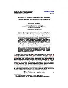
Fig. 1. Experimental stand (upper) and computational geometry (lower) with basic dimensions and boundary conditions.
The computational domain was prepared in relation to the experimental stand which is developed in parallel – see Figure 1. It consists of a part of a channel at the top through which dry air is flowing and wet material at the bottom as shown in Figure 1. Due to symmetry a half of the channel and sample are considered. The assumed basic dimensions and boundary conditions are presented in Figure 1. Subsequently, the structural mesh with over 3.6 million of elements was generated applying the sweep method. The grid for the air region was refined close to the channel walls and contact surface between the air and moist brick as well as in the region which refers to walls of the brick. The maximum aspect ratio of the mesh was 98.9. Before implementation the mathematical model of transport phenomena in the porous building material in the ANSYS Fluent following assumptions were introduced:
4
MATEC Web of Conferences 240, 01022 (2018) ICCHMT 2018
https://doi.org/10.1051/matecconf/201824001022
Table 1. Thermophysical parameters of dry brick, liquid water, water vapour and dry air
scalar equations in the fluid region in which turbulent air flow occurred.
Property
4 Results
Brick porosity
The simulations were carried out in two steps. In the first step the flow filed in the channel in the steady-state was found by simulating the air flow in the channel with periodic boundary conditions. Then in the second step only scalar balance equations were solved in the transient simulation with steady flow field obtained in the previous step. The boundary at the inlet to the computational domain were following: the dry air and water vapour densities were equal to 1.225 and 0.00968 kg/m3, respectively, while the mixture velocity and temperature were 10 m/s and 23.8C, respectively. The initial conditions for the transient simulation were following: the flow field from the periodic simulation of the air flow in the channel with the parameters the same as at the inlet to the channel, while the brick was at 23.8C and pores were fully filled with the liquid water which volume fraction was 13%. The dry air and water vapour densities in the brick were equal to 0. The thermo-physical parameters used in the simulations are given in Table 1. The closing relationships for the system of governing equations, eq. (19)-(22), were following [18]: Pores area for unite volume: 6 as d av 1 s
Value
p
0.14
Capillary moisture content Wcap (kg/m3)
130.0
Average pore diameter dav (m)
1.610-5
Brick density s (kg/m3)
1800.0
Brick thermal conductivity ks (W/m/K)
0.77
Brick specific heat cs (J/kg/K)
880.0
Liquid water density l (kg/m3)
1000.0
Liquid water conductivity kl (W/m/K)
0.62
Liquid water specific heat cl (J/kg/K)
4190.0
Liquid water surface tension (N/m) Water vapour resistance diffusion factor Cdry Water vapour conductivity kv (W/m/K)
(23)
7.210-4 24.79 0.018
Effective thermal conductivity of the brick and moist air:
Water vapour specific heat cv (J/kg/K)
1864.0
kef k s 0.0047W
(24a)
Water vapour molecular mass Mv (kg/kmol)
18
(24b)
Latent heat of evaporation hvap (J/kg)
2.6106
Dry air thermal conductivity kg (W/m/K)
0.026
Dry air specific heat ca (J/kg/K)
1005.0
Brick permeability for moist air Kg (m2/s)
1.1510-12
Minimal saturation smin
0.25
Universal gas constant B (J/mol/K)
8.314
kg
a k a v kv a v
Volumetric moisture content: W l l v g
(25)
Vapour mass diffusivity in the brick and dry air:
W 2.61 10 M v 1 Wcap (26a) 2 W Cdry BT 0.503 1 0.497 W cap 5
Dv a ,ef
p pv, sat pv , sat exp c l BT
1.75
T Dv a =2.23 10 5 273.13
(26b)
Water vapour density for saturation conditions:
v , sat
pv, sat M BT
Modified saturation pressure:
Saturation pressure:
T 273.15 pv , sat 614.3exp 17.06 T 40.25
(27)
5
(28)
(29)
MATEC Web of Conferences 240, 01022 (2018) ICCHMT 2018
Capillary pressure:
pc
1.417 1 S 2 2.120 1 S K g 1 s 3 1.263 1 S
(30)
Modified saturation: S
https://doi.org/10.1051/matecconf/201824001022
s smin 1 smin
(31)
Saturation: s
l 1 s
(32)
where: B denotes the universal gas constant, Cdry is the water vapour resistance diffusion factor, dav stand for the average pore diameter, Kg denotes the permeability of the porous building material for moist air, Mv is the molecular mass of vapour, smin is the minimal saturation for water in the pendular form, Wcap denotes the capillary moisture content and is the water surface tension.
Fig. 3. Temporal variations of moisture content at the brick top surface and various depths for two values of the mass transfer coefficient between liquid water and moist air in the porous material
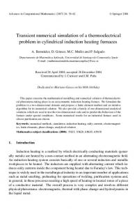
In this paper the influence of the mass transfer coefficient between liquid water and moist air in the porous material (evaporation speed) was analysed. Two values of this coefficient were assumed, i.e., 7.7610-4 and 5 m/s. The obtained temperature temporal variations at the brick top surface and at different depths inside the brick body are presented in Figure 2. For higher value of mass transfer coefficient the drying process was faster than for the lower one – see Figure 3. The temperature drops for the higher coefficient at different depths in the brick reached maximum after 30 to 60 minutes from the beginning of drying and temperature at the sample surface decreases below 23.3C (lower part of Figure 2). The temperature drops for the lower coefficient reached maximum after 4 to 6 hours and temperature at the sample top surface decreases to 23.69C (upper part of Figure 2). These values of temperature drops were lower than reported in the literature. This was probably caused by neglection of the capillary liquid moisture transport, which upholds evaporation. The second factor which might affect temperature drops was high mass and heat transfer rate between the air and brick. High speed of flowing air (10 m/s) resulted in the intensive convective mass and heat transport at the brick surface and lower temperature drops inside the brick.
Fig. 2. Temporal variations of brick temperature at the brick top surface and various depths for two values of the mass transfer coefficient between liquid water and moist air in the porous material
6
MATEC Web of Conferences 240, 01022 (2018) ICCHMT 2018
https://doi.org/10.1051/matecconf/201824001022
The shapes of the temporal temperature curves presented in Figure 2 partially agree with data presented in the literature. The real drying curves are divided in three periods, i.e., initial temperature drop, temperature plateau and temperature increase in the final period. In Figure 2 during the first period of drying process, temperature falling rates were high as a consequence of the intensive evaporation of the liquid water. Unfortunately, the second period of drying process with constant temperature was not observed in presented simulations. Only for the deepest monitors in the brick (see curves for 30 mm in Figure 2) the flattened temperature curves might be found. The temperature after reaching the lowest values started to rise. The temperature plateau in the second period is partially caused by the capillary pressure gradient, which results in transport of liquid water to the drier regions and upholds isothermal evaporation. However, capillary movement of the liquid water was not accounted for in the present model, hence the constant temperature periods were not observed or were very short. In the last period of the drying process the predicted temperature growths were slowed by evaporation in the internal parts of the brick. These growths were slower than presented in literature because of more intensive evaporation inside the brick. Temporary variations of the local moisture content at the brick top surface and various depths inside the brick were presented in Figure 3. For higher value of the mass transfer coefficient between liquid water and moist air in the porous building material the drying process was faster and water amount decreased more rapidly. At first water evaporated from the surface of the brick and then from the deeper regions inside the body of the brick. Although the surface was dried out or almost dried the internal parts of the brick were still wet.
The model allowed to predict variations of temperature and moisture content in the brick. However, the obtained results did not exhibit the same character of the drying temperature curves as these presented in the literature. Neglecting the capillary movement of the liquid water in the brick and assuming high heat and mass transfer rates between the flowing air and the brick top surface might be sources of this discrepancy. The future work will be related to the implementation of the full mathematical model in the ANSYS Fluent with the free liquid water motion accounted for, determination of missing thermophysical parameters of the brick as well as its verification and validation. The complete numerical model will be used for parametric investigations and optimisation of the drying phenomena in the building materials.
7 Conclusions
6.
This work was supported by the National Centre for Research and Development (Poland) under grant no. POIR.04.01.02-000099/16 Development of innovative technology of drying and moisture sealing of masonry walls, DryWall and the statutory funds of Faculty of Power and Aeronautical Engineering of Warsaw University of Technology.
References 1. 2.
3. 4. 5.
In the paper complex non-equilibrium mathematical model of a drying process in the porous building materials was formulated. Three phases of moisture were considered to reside in the brick, i.e., water vapour in the moist air filling the pores, liquid water (bound water) adsorbed at the surface of the solid component of the material and free liquid water either in a discontinuous form (funicular) or continuous one (pendular). The model accounted for moisture diffusion and convection due to gravitational acceleration as well as gradients of moist air and capillary pressures inside the material. The model in a simplified form, i.e., with motion of the liquid water and convection of moist air as well as capillary forces in the porous building material neglected, was implemented in the commercial software ANSYS CFD with the aid of its advanced customisation functionalities like the User-Defined Function, User-Defined Scalar and User-Defined Memory. Subsequently, the model was coupled with heat and fluid flow model in air. Then the model was applied to initial investigations of drying of a single moist brick placed in the channel with flowing dry air.
7.
8. 9. 10. 11. 12. 13. 14. 15.
7
P.B. Lourenço, E. Luso, M.G. Almeida, Build. Environ. 41, 223 (2006) N. Karagiannis, M. Karoglou, A. Bakolas, M. Krokida, A. Moropoulou, Constr. Build. Mater. 137, 441 (2017) N. Mendes, F.C. Winkelmann, R. Lamberts, P.C. Philippi, Energy Build. 35, 631 (2003) O.F. Osanyintola, C.J. Simonson, Energy Build. 38, 1270 (2006) R.C. Shoemaker, D.E. House, Neurotoxicol. Teratol. 28, 573 (2006) L. Falchi, D. Slanzi, E. Balliana, G. Driussi, E. Zendri, Build. Environ. 131, 117 (2018) A.M. Gueli, V. Garro, M. Liuzzo, G. Margani, S. Pasquale, G. Politi, G. Stella, Measurement 118, 289 (2018) T. Defraeye, Appl. Energy 131, 323 (2014) J. Fan, X. Wen, Int. J. Heat Mass Transf. 45, 4045 (2002) X. Cheng, J. Fan, Int. J. Therm. Sci. 43, 665 (2004) P. Łapka, P. Furmański, T.S. Wiśniewski, Int. J. Numer. Methods Heat Fluid Flow 27, 1078 (2017) P. Łapka, P. Furmański, Przem. Chem. 96, 343 (2017) P. Łapka, P. Furmański, Heat Mass Transf. 54, 2461 (2018) P. Furmański, P. Łapka, Int. J. Heat Mass Transf. 114, 1331 (2017) G.H. dos Santos, N. Mendes, Int. J. Heat Mass Transf. 52, 2390 (2009)
MATEC Web of Conferences 240, 01022 (2018) ICCHMT 2018
https://doi.org/10.1051/matecconf/201824001022
16. M. Van Belleghem, M. Steeman, H. Janssen, A. Janssens, M. De Paepe, Build. Environ. 81, 340 (2014) 17. M. Steeman, M. Van Belleghem, M. De Paepe, A. Janssens, Build. Environ. 45, 2202 (2010) 18. M. Kaviany, Principles of heat transfer in porous media (Springer, New York, 1995)
8