ARTICLE International Journal of Advanced Robotic Systems
Mathematical Programming Method Based on Chaos Anti-Control for the Solution of Forward Displacement of Parallel Robot Mechanisms Regular Paper
Youxin Luo1,*, Qiyuan Liu1 and Xiaoyi Che1 1 College of Mechanical Engineering, Hunan University of Arts and Science, Changde, P. R. China * Corresponding author E-mail:
[email protected]
Received 4 Aug 2012; Accepted 2 Nov 2012 DOI: 10.5772/54818 © 2013 Luo et al.; licensee InTech. This is an open access article distributed under the terms of the Creative Commons Attribution License (http://creativecommons.org/licenses/by/3.0), which permits unrestricted use, distribution, and reproduction in any medium, provided the original work is properly cited.
Abstract The pose of the moving platform in parallel robots is possible thanks to the strong coupling, but it consequently is very difficult to obtain its forward displacement. Different methods establishing forward displacement can obtain different numbers of variables and different solving speeds with nonlinear equations. The nonlinear equations with nine variables for forward displacement in the general 6‐6 type parallel mechanism were created using the rotation transformation matrix R , translation vector P and the constraint conditions of the rod length. Given the problems of there being only one solution and sometimes no convergence when solving nonlinear equations with the Newton method and the quasi‐Newton method, the Euler equation for free rotation in a rigid body was applied to a chaotic system by using chaos anti‐control and chaotic sequences were produced. Combining the characteristics of the chaotic sequence with the mathematical programming method, a new mathematical programming method was put forward, which was based on chaos anti‐control with the aim of solving all real solutions of nonlinear equations for www.intechopen.com
forward displacement in the general 6‐6 type parallel mechanism. The numerical example shows that the new method has some positive characteristics such as that it runs in the initial value range, it has fast convergence, it can find all the possible real solutions that be found out and it proves the correctness and validity of this method when compared with other methods. Keywords Chaos Anti‐Control, Parallel Mechanism, Mathematical Programming Method, Nonlinear Equations
1. Introduction The pose of the moving platform in parallel robots can be realized thanks to the strong coupling, however this also means it is very difficult to obtain its forward displacement. The Stewart mechanism is a general 6‐6 type parallel mechanism whose upper and lower platforms are flat arbitrary hexagons connected by 6
Int J Adv Robotic Sy, 2013, Vol. Anti-Control 10, 32:2013 Youxin Luo, Qiyuan Liu and Xiaoyi Che: Mathematical Programming Method Based on Chaos for the Solution of Forward Displacement of Parallel Robot Mechanisms
1
sliding pairs with spherical pairs at both ends. The position solutions ultimately boil down to solving a set of nonlinear equations. Solving these equations is extremely difficult and we are faced with which is another difficult problem of mechanism even after completing the displacement analysis in the space 6R series mechanical arm [1]. The forward displacement of the Stewart mechanism is a class of strongly nonlinear algebraic equations with many variables. Different methods establishing forward displacement can obtain different numbers of variables and different solving speeds in nonlinear equations. For a long time, many scholars at home and abroad have researched this problem [2‐11]. Wampler CW [2] carried out a forward displacement analysis of general six‐in‐ parallel SPS (Stewart) platform manipulators using soma coordinates. Innocenti C. [3] solved the problem of forward kinematics in polynomial form of the general Stewart platform. Rolland L. [4] solved the forward kinematics problem with an exact algebraic method for the general parallel manipulator. Wang Y. [5] solved forward kinematics of general Stewart‐Gough platforms with a direct numerical solution. Liang [6] and W. Lin [7] achieved forward displacement of the triangle and quadrangle platform‐type parallel robot respectively with the use of coincidence hinges, and C.D. Zhang [8] achieved forward displacement of the hexagonal platform‐type parallel robot. Compared with the platform type, the 3‐D type can effectively avoid the interference of branch chains and extend the working space of the moving platform and the swing range of positive angle. But it exacerbates the coupling of the pose in the moving platform so that it is more difficult to obtain forward displacement. Based on the basic constraint equations of the parallel robot, intermediate variables and mathematical processing in Matlab, three independent equations were established that use the positive angles of the moving platform as the variables [9]. Nonlinear equations which have forward displacements as four variables in a platform‐type parallel mechanism were set up [10], and nonlinear equations with seven variables in 3‐D parallel mechanism were built [11]. The methods for solving forward displacement in the Stewart platform generally have an analytic and a numerical method. The analytic method for finding the closed form of the forward displacement can give the exact solution, but often generates the middle polynomial which is too large and so is hard to calculate [12]. For the kinematics of the Stewart platform, steps were taken to obtain an estimated number of solutions, some of the real solutions and the closed form of some special configuration, but this is still a long away from completely solving all the real solutions of the equations [13‐17]. The numerical methods used for the Stewart 2
Int J Adv Robotic Sy, 2013, Vol. 10, 32:2013
platform are mainly the Newton‐Rapbson iterative method (referred to as NR method) [18], the homotopy method [19‐21], the chaotic method [22], the neurons algorithm [23], the additional sensor method [24], etc.. The NR method does not need to solve the complex nonlinear equations with n‐order. But in the NR method the calculation speed is unstable, and its convergence of the calculation results and the speed of convergence are all dependent on the initial value. The homotopy and the neurons methods can work out all the solutions, but require large amounts of calculation. The additional sensor method uses the necessary number of additional sensors and a certain arrangement to simplify the solving process of forward displacement position, but the simple additional sensor method has a very high demand with regards to the level of error in the processing and assembling platform parts so that it makes it difficult to calibrate the platform structure. In the numerical iteration method or the constraint optimization method, if the initial value selected is improper, the convergence of the result is more difficult and all the solutions are more difficult to obtain. This problem has not been fully resolved until now, thus it has been the research focus of many scholars [25]. The Newton iterative method is the traditional numerical iterative method and it has second‐order convergence and high performance but this method is extremely sensitive to initial values. Sometimes this phenomenon is considered to be the arithmetic singularity or inevitable singularity, in fact, the reason for the numerical instability is that the NR method is a nonlinear discrete dynamical system where the chaos and fractal phenomena will be generated in the sensitive area. In mechanism and optimal design, the chaos phenomenon is considered to be incomprehensible and unusable, or it is regarded as random figment of the imagination to be ignored. The rapid development of chaos theory is one of the major achievements of the last century [26]. With the continuous development of society, many nonlinear phenomena and models continue to emerge and so research in this field is on the rise. The international academic community ge nerally sees non‐li near mathematics, nonlinear natural science and social science and their technological development as part of the mainstream in the 21st century, while chaos is the basic pattern of almost all sports phenomenon in the natural world. Chaos is considered to be a phenomenon that is seemingly irregular and similar to a ‘random’ in a deterministic system. The most essential characteristic of chaotic behaviour is extreme sensitivity to the initial conditions of the nonlinear system. It has many basic characteristics such as boundedness, ergodicity, intrinsic randomness, scaling, universality, fractal dimension, the positive Lyapunov exponent, unlimited broadband power spectrum and sub‐dimensional power spectrum. www.intechopen.com
The Lyapunov exponent is one of a number of effective methods for depicting the chaos specific property of a nonlinear system. If one of the Lyapunov exponents is positive, the system is chaotic, and if a system has two or more positive Lyapunov exponents, the system is hyper‐ chaotic. The greater the number of positive Lyapunov exponents, the higher the degree of instability in the system [27, 28]. It is of important theoretical and practical significance that the chaotic and hyper‐chaotic systems are used to calculate kinematics. The chaos method can calculate all the real solutions within the scope of the real number and it has high computational efficiency because it does not seek plural results. Of course, imaginary solutions could not be obtained with this method. The method described in Y.X. Luo, D.Z. LI (2003) [22] considers that the points of Julia centralization in the Newton iteration method will appear in the neighbourhood where the Jacobian matrix of the equations is equal to zero. But this guess has not been proven. For the multivariable Jacobian matrix, first, its symbolic expression is found; second, all the variable values are determined except for one variable; finally, the chaos zone is searched for the variable to be determined. So solving the matrix is quite complex. The chaotic sequence method is a new method, in which the initial point of the Newton iteration is generated using the chaotic and hyper‐chaotic system and all the real solutions in the mechanism synthesis can be effectively solved [28‐32]. But the Hénon hyper‐chaotic Newton iteration method cannot solve the mechanism synthesis problem of 6‐SPS. When the solutions do not converge using the Newton method or the quasi‐Newton method, the mathematical programming method can be adopted [33]. The mathematical programming method together with the hyper‐chaotic system was put forward to solve the synthesis problem of 6‐SPS by transforming it into nonlinear equations with six variables [34]. The Hénon super‐chaotic sequence was combined with the Newton descent method to create the super‐chaotic Newton descent method in order to solve this problem by transforming it into nonlinear equations with nine variables [35]. The quaternion method was used to establish nonlinear equations in the synthesis problem of 6‐SPS with eight variables and it was solved by using the hyper‐chaotic neural networks damped least‐square method where the hyper‐chaotic neural network produces the hyper‐chaotic sequence as the initial iteration value in the damped least‐square method [36]. In this paper, nonlinear equations with nine variables on forward displacement in the general 6‐6 type parallel mechanism were created using the rotation transformation matrix R , translation vector P and the constraint conditions of the rod length and the mathematical programming method based on chaos anti‐ control was proposed as a means to solve forward displacement in the general 6‐6 type parallel mechanism. www.intechopen.com
The Euler equation for the free rotation of a rigid body was converted to the chaotic system by using chaos anti‐ control and chaotic sequences were produced. By combining the characteristics of the chaotic sequence with the mathematical programming method, all the solutions of the equations on forward displacement were solved. The numerical example shows that the new method has fast convergence, it can find all the possible real solutions that be found out and it proves the correctness and validity of this method when compared with other methods. 2. Chaotic anti‐control of rigid motion Chaos control can suppress or eliminate chaotic dynamical behaviour. Chaotic anti‐control, through external input or adjustment to internal parameters, mainly results in the original non‐chaotic system becoming chaos or the chaos of the original system becoming stronger. In order to implement the control and anti‐control of chaos, the controller should be designed as simply as possible in order to ensure low‐cost, easy realization and convenient use. The creation of a chaos generator to implement chaotic anti‐control is a problem for engineering design. A successfully designed, simple and strict chaos controller demands an equivalent level of competency in mathematics and the capability in the engineering design [27,28]. Feedback control is one of the basic methods for the control and anti‐control of chaos. The linear feedback controller is the simplest controller that can be used to implement chaotic anti‐control. Using Lyapunov exponents of control or anti‐control of chaos is one of a number of effective ways to describe the chaotic properties of nonlinear systems. The number of Lyapunov exponents is the same as the dimension n of the state space of the system. If one of the Lyapunov exponents is greater than zero, the system is chaotic, and if at least two of Lyapunov exponents are positive, the system is hyper‐chaotic. The greater the number of positive Lyapunov exponents, the higher the degree of instability in the system. The Euler equations of free rotation of the rigid body are given in Chen H K, Lee C (2004) [27] and Y.X. Luo (2008) [28] as:
I1 1 ( I 2 I 3 )23 M1 I 21 ( I 3 I1 )31 M2 (1) I ( I I ) M 1 2 1 2 3 3 1
where I 1 , I 2 and I 3 are the main moments of inertia, 1 , 2 and 3 are the angular velocities of the spindle, and M1 , M 2 and M3 are the imposed torques, respectively. Through the linear feedback system, a non‐chaotic free rotation system of rigid body is transformed into a
Youxin Luo, Qiyuan Liu and Xiaoyi Che: Mathematical Programming Method Based on Chaos Anti-Control for the Solution of Forward Displacement of Parallel Robot Mechanisms
3
chaotic system. Because the angular velocities are the changing parameters of the system (Note: The mechanism synthesis only requires that chaotic sequences be produced without considering the parameter detection. Of course, it is easy to detect the angular velocities in this engineering system), the imposed moments are feedbacked linearly by the angular velocities, that is, M A , where a11 0 A 0 a22 0 0
0 0 a33
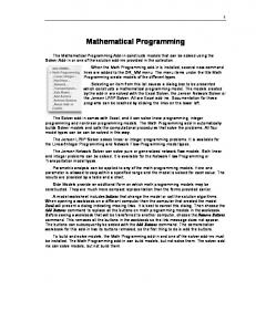
Figure 2. Lyapunov exponent of system
Supposed 1 x , 2 y , 3 z , a a11 / I1 , b a22 / I 2 , and c a33 / I 3 , Eq.(1) is transformed into Eq.(2) as follows
I2 I3 yz ax x I1 I 3 I1 xz by (2) y I2 I I z 1 2 xy cz I3
The conditions whereby the system produces chaos are as follows [32]: 0 a (b c) 1. a 0, b 0, c 0 , and or b 0, a 0, c 0 ,
and
0 b ( a c)
or
c 0, b 0, a 0 and 0 c (b a) ;
2.
I2 I3 I I I I 0, 3 1 0, 1 2 0 , that is, I 3 I1 I 2 ,or I1 I2 I3 I2 I3 I I I I 0, 3 1 0, 1 2 0 , that is, I 2 I1 I 3 I1 I2 I3
Selected I 3 3 I 0 , I1 2 I 0 , I 2 I 0 (to meet I 3 I1 I 2 ), a 5, b 10, c 3.8 (to meet a 0, b 0, c 0 and 0 a (b c) ), the strange attractor of the system is as shown in Fig.1 and the Lyapunov exponent in Fig.2. It is seen in these Figures that this system is chaos.
3. The mathematical programming method for nonlinear equations The Newton iteration method as a traditional method is an important iterative technique for problems that are one‐dimensional and multi‐dimensional. When the solutions do not converge using the Newton method or the quasi‐Newton method, the mathematical programming method can be adopted [33].
The nonlinear equation is given as:
fi ( x) 0( x D Rn ; i 1,2,, n) (3)
where, fi ( x) has a continuous second‐order derivative on the open convex set, and fi ( x * ) 0(i 1,2, , n) at x * D . Assuming si sign( fi ( x 0 ) , x 0 is an initial point of D . According to the continuity of the function, there exits the following equations at x near x 0 :
si fi ( x) 0(i 1,2, , n) (4)
Then Eq.(3) is transformed as:
n
si fi (x) min i 1
( x D)
(5)
si fi ( x) 0 (i 1,2,, n). n
Because si fi ( x) 0 , si fi ( x) 0 . fi ( x* ) 0 is substituted i 1
into Eq.(5). The constraint conditions are satisfied and the target value is zero, so x * is the solution in Eq. (5). On the contrary, if there is no solution in Eq.(3), the optimal point in Eq.(5) must not become the solution in Eq.(3). If fi ( x ) has a discontinuous second‐order derivative on the open convex set, the derivative can be replaced by the difference. 4. The mathematical programming method based on chaotic anti‐control for solving nonlinear equations Figure 1. Strange attractor of system 4
Int J Adv Robotic Sy, 2013, Vol. 10, 32:2013
Using the mathematical programming method based on chaotic anti‐control, all solutions of nonlinear equations can be obtained. The calculation steps are as follows: www.intechopen.com
1.
Constructing the chaos set x0 (i , j ) according to Eq.
(2), i 1,2, , n where n is the number of variables, and j 1,2,, N where N is the length of chaos sets. 2.
Supposing that the variable interval of x(i ) is
[a(i), b(i)] , the chaos set is mapped to the variable interval to generate the jth initial value of x(i ) , that is, x(i , j) . 3.
x(i , j) regarded as the initial value of the mathematical programming method, Eq. (5) has been iterated j times, then all the solutions x * are obtained.
In accordance with the protocol for the fmincon function in Matlab, the objective function @myopt_two and the constraint function @myconstr_two are written, and the Matlab function as fmincon or fminimax is run for each initial value. %%%%%%%%%% function y=myopt_two(x) f=myfun(x);% myfun(x)corresponding to nonlinear equations to find! [N,N0]=size(f); for i=1:N s(i)=sign(f(i)); end y=0; for i=1:N y=y+s(i)*f(i); end function [c,ceq]=myconstr_two(x) f=myfun(x); [N,N0]=size(f); for i=1:N s(i)=sign(f(i)); end ceq=[]; for i=1:N c(i)=‐s(i)*f(i); end %%% part of main program %%% OPT=optimset(ʹLargeScaleʹ,ʹoffʹ);OPT.TolCon = 1e‐0015; OPT.MaxFunEvals=2000;OPT.TolFun= 1e‐0020; kgg=1;%kgg=1(fmincon);kgg=2(fminimax); % x is initial value produced by Eq.(2) and mapped to variable interval if kgg==1 [xopt,ff0]=fmincon(@myopt_two,x,[],[],[],[],[],[],@myco nstr_two,OPT); else [xopt,ff0,c]=fminimax(@myopt_two,x,[],[],[],[],[],[],@myco nstr_two,OPT); End %%%%%%%% www.intechopen.com
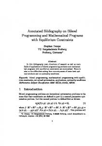
5. Mathematical modelling of forward displacement The structural diagram of the general 6‐6 type 3‐D parallel mechanism is shown in Fig.3. In this mechanism, the upper plane is connected to the lower by six branched chains with ball joints and sliding pairs. The fixed coordinate system O1x1y1z1 and the moving system O2 x2 y2 z2 are established respectively in Fig.3, where, the coordinates of Ai and Bi are Qia ( axi , ayi , azi ) and Qib (bxi , byi , bzi ) respectively, and the length of Ai Bi is Li (i 1,2, ,6) . So as long as the rotation transformation matrix R and the translation vector P( x , y , z) from O2 x2 y2 z2 to O1x1y1z1 are obtained, the spatial position of the upper plane relative to the lower can be determined.
Figure 3. Structural diagram of the general 6‐6 type 3‐D parallel mechanism
From the condition of the rod length, the following equations can be obtained:
L2i [RQib P Qia ]T [RQib P Qia ]
(i 2,3,,6)
(6)
L21 P TP (7)
l x where, R ly lz
nx ny nz
mx my mz
After substituting Eq.(3) into Eq.(2) and expanding it, we can obtain the equation as:
2
2
T
T
T
T
T
L1 Li QibQib QiaQia 2P RQib 2QiaP 2QibRQia 0 ( i 2,3, ,6)
(8)
R is the unit orthogonal matrix, so the following equations can be obtained:
lx2 ly2 lz2 1 (9)
mx2 my2 mz2 1 (10)
lx mx ly my lz mz 0 (11)
Youxin Luo, Qiyuan Liu and Xiaoyi Che: Mathematical Programming Method Based on Chaos Anti-Control for the Solution of Forward Displacement of Parallel Robot Mechanisms
5
nx ly mz lz my (12)
ny lz mx lx mz (13)
nz lx my ly mx (14)
From the Eqs. (12‐14), nx , ny and nz can be obtained. Therefore, Eqs. (6‐11) are the key and also the difficulty of the forward displacement in the general 6‐6 type 3‐D parallel mechanism [35]. They are also the mathematical models in this paper which are denoted by the following equation as:
F( x), F( x) [ f1( x), f2 ( x),, fn ( x)]T . where, there are nine unknown variables lx , ly , lz , mx , my , mz , x, y and z, which are written by x [lx , ly , lz , mx , my , mz , x , y , z ]T . 6. Numerical example In Fig.3, the coordinate of point Ai in a static coordinate system x1y1z1 is A1(0,0,0) , A2 (2,0,0) , A3 (4,1,0) , A4 (5,3,1) , A5 (3,5, 1) , A6 ( 1,2,2) , and the coordinate of point Bi in a dynamic coordinate system x2 y2 z2 is B1 (0,0,0) , B2 (1,0,0) , B3 (2,1,0) , B4 (4,3,2) , B5 (3,4, 1) , B6 ( 2, 1,3) , l1 11 , l2 12 , l3 13 , l4 15 , l5 14 , l6 10 , thus finding the mechanism’s total position forward solutions.
First we put all the data into F( x) and transform it into Eq.(5), then we compile the objective function and constrained function and we take the chaos series from Eq.(2) and use it as an anti‐control of the chaos mathematical programming method’s initial value x 0 . Then we use the fmincon function to find solutions and the answer comes out automatically as 4 independent real solutions, as you can see in Tab. 1. The corresponding initial values to four real solutions are shown in Tab. 2 and the corresponding Euler angles to four real solutions are shown in Tab. 3. It takes just 30.65s. If we adopt the Euler method to solve a similar problem, it will take 327.5 s, as shown in Table 3, which is the same as Table 1 in Ref. [36], and, based on the quaternion and hyper‐chaotic damp least square method, it will take 3.8s, which is shown in Table 4 and can be changed into Table 3 (Notice the order of solutions is not the same). If we use the fminimax function to run the anti‐control of the chaos mathematical programming method, it will take 45.5s to find all the solutions, which are shown in Tab. 5, Tab. 6 and Tab. 7. Actually, Tab. 1 and Tab. 3 are the same as Tab. 5 and Tab. 7, the only difference is the order of solutions and corresponding initial values are not for the same data. 6
Int J Adv Robotic Sy, 2013, Vol. 10, 32:2013
No
x(1)
x(2)
x(3)
x(4)
x(5)
1 2 3 4
0.4756 0.2181 ‐0.8060 ‐0.7491 x(7)
0.6472 0.7245 ‐0.5912 ‐0.3823 x(8)
‐0.6076 ‐0.6314 0.9820 0.6784 x(9)
‐0.7939 ‐0.6849 ‐0.0872 ‐0.6574
No
‐0.5958 ‐0.6539 0.0291 ‐0.5410 x(6)
1 2 3 4
0.0240 ‐0.3637 0.1673 0.3280
0.3682 0.2301 ‐1.1889 ‐1.8184
5.3866 3.8573 ‐0.3137 1.1055
9.5838 10.2989 ‐10.9311 ‐10.7922
Table 1. Four real solutions in example based on the fmincon function No
x 0 (1)
x 0 (2)
x 0 (3)
x 0 (4)
x 0 (5)
1 2 3 4
3.8331 8.6791 18.0609 6.6078
18.9344 12.9233 ‐12.2904 ‐15.4687
16.5555 19.2938 ‐7.7260 ‐10.6561
4.0941 ‐4.6738 ‐19.1705 ‐18.6276
‐15.6880 ‐17.6221 6.6365 8.6550
No
x 0 (6)
x 0 (7)
x 0 (8)
x 0 (9)
1 2 3 4
‐10.8061 ‐14.1385 2.9570 7.4146
8.3421 12.2140 15.6562 ‐5.2656
7.0324 9.7839 22.2158 5.9026
17.0948 18.8669 ‐9.7348 ‐12.4049
Table 2. Corresponding initial values to four real solutions based on the fmincon function No.
x1
x2
1 2 3 4
0.5116 0.2768 ‐0.1554 ‐0.8487
x3
x4
x5
x6
0.3675 0.9636 0.3682 5.3866 0.5113 ‐0.6170 0.2301 3.8573 0.3434 ‐0.7563 ‐1.1889 ‐0.3137 0.2703 ‐0.4596 ‐1.8184 1.1055
9.5838 10.2989 ‐10.9311 ‐10.7922
Table 3. Corresponding Euler angles to four real solutions based on fmincon function No.
q0
q1
q2
q3
1 2 3 4
0.2484 ‐0.6578 ‐0.4079 0.3051
0.3337 ‐0.2861 ‐0.2512 0.3302
‐0.3096 ‐0.1538 0.0703 ‐0.1000
0.8550 0.6796 0.8750 0.8876
No.
g0
g1
g2
g3
1 2 3 4
‐7.6883 7.0399 8.9082 ‐8.0901
6.5440 ‐1.1127 2.4680 5.8517
4.1984 4.1411 3.8515 4.4810
1.1998 7.2837 4.5518 1.1085
Table 4. Four real results in example based on the quaternion hyper‐chaotic mathematical programming method No
x(1)
x(2)
x(3)
x(4)
x(5)
1 2 3 4
‐0.5410 0.0291 ‐0.6539 ‐0.5958
‐0.7491 ‐0.8060 0.2181 0.4756
‐0.3823 ‐0.5912 0.7245 0.6472
0.6784 0.9820 ‐0.6314 ‐0.6076
‐0.6574 ‐0.0872 ‐0.6849 ‐0.7939
No
x(6)
x(7)
x(8)
x(9)
1 2 3
0.3280 0.1673 ‐0.3637
‐1.8184 ‐1.1889 0.2301
1.1055 ‐0.3137 3.8573
‐10.7922 ‐10.9311 10.2989
Table 5. Four real solutions in example based on the fminimax function www.intechopen.com
No
x 0 (1)
x 0 (2)
x 0 (3)
x 0 (4)
x 0 (5)
1 2 3 4
8.9356 ‐12.2332 ‐1.2653 18.1297
‐7.3843 ‐13.3778 ‐0.6427 14.2257
‐23.2098 ‐1.6282 16.5755 ‐7.3212
1.4542 ‐4.4741 ‐24.3078 18.7107
‐19.5729 ‐10.9516 14.1811 ‐3.2882
No
x 0 (6)
x 0 (7)
x 0 (8)
x 0 (9)
1 2 3 4
‐26.6771 4.1759 6.1127 ‐16.5012
‐20.0986 ‐21.6999 17.8157 ‐7.1409
‐19.7039 ‐24.1529 18.0167 ‐8.4078
‐23.8358 ‐1.8470 16.7416 ‐8.2568
Table 6. Corresponding initial values to four real solutions based on the fminimax function No.
x1
1 2 3 4
‐0.8487 ‐0.1554 0.2768 0.5116
x2
x3
x4
x5
x6
0.2703 ‐0.4596 ‐1.8184 1.1055 ‐10.7922 0.3434 ‐0.7563 ‐1.1889 ‐0.3137 ‐10.9311 0.5113 ‐0.6170 0.2301 3.8573 10.2989 0.3675 0.9636 0.3682 5.3866 9.5838
Table 7. Corresponding Euler angles to four real solutions based on the fminimax function
7. Conclusions In the problem of the forward displacement of parallel robots, we need to solve a class of strongly nonlinear algebraic equations with many variables which are consequently extremely difficult to solve. Different methods establishing forward displacement can obtain different variable numbers and different solving speeds in nonlinear equations. The nonlinear equations with nine variables for forward displacement in the general 6‐6 type parallel mechanism were built up using the rotation transformation matrix R , translation vector P and the constraint conditions of the rod length. The mathematical programming method based on chaotic anti‐control was proposed in order to solve forward displacement in the general 6‐6 type parallel mechanism. The Euler equation for free rotation in a rigid body was converted to a chaotic system by using chaos anti‐control and chaotic sequences were produced. Combining the characteristics of the chaotic sequence with the mathematical programming method, all the real solutions of forward displacement were solved and the calculation steps were shown. This method solves the problems resulting from no convergence in the Newton method and the quasi‐ Newton method, based on chaos and super‐chaos. The numerical example shows that the method proposed in this paper is verified as correct and effective. Since this method runs within the real range, it provides a new approach for solving forward displacement in the parallel mechanism and other strongly nonlinear equations. 8. Acknowledgments This research is supported by the National Natural Science Foundation of P.R. China (No:51075144) and the grant of the 12th Five‐Year Plan for the construct program www.intechopen.com
of the key discipline (Mechanical Design and Theory) in Hunan province(XJF2011[76]). 9. References [1] F.A. Wen, C.G. Liang, Q.Z. Liao (1999) The forward displacement analysis of parallel robotic mechanisms, China Mechanical Engineering, 10(9), pp.1011‐1013. [2] C.W. Wampler (1995) Forward displacement analysis of general six‐in‐parallel SPS (Stewart) platform manipulators using soma coordinates. Mech Mach Theory, 31(3),pp. 331–337. [3] C. Innocenti (2001) Forward kinematics in polynomial form of the general Stewart platform. ASME J Mech Des., 123(2),pp. 254–260. [4] L. Rolland (2005) Certified solving of the forward kinematics problem with an exact algebraic method for the general parallel manipulator. Adv Rob., 19(9), pp. 995–1025. [5] Y. Wang (2007) A direct numerical solution to forward kinematics of general Stewart‐Gough platforms. Robotica, 25(1), pp. 121–128. [6] C.G. Liang, H. Rong (1991) Forward Kinematics Analysis of the Stewart Platform Robot Arm. Journal of Mechanical Engineering, 27(2), pp.26‐30. [7] W. Lin, M. Griffs, J. Duffy (1992) Closed‐form Forward Displacement Analysis of the 4‐5 in Parallel Platforms, Proc. ASME Des. Tech. Cont., 45, pp. 521‐ 527. [8] C.D. Zhang, M. Song (1992) Forward Position Analysis of Nearly General Stewart Platforms. Proc. ASME Conf. on Rob. Spatial Mechanism and Mechanical Systems, 45, pp.81‐84. [9] K.J. Lu (2003) 3D Searching for the Position Solution to the Parallel Robot Manufacture Information Engineering of China, 32(5), pp.107‐109. [10] S.W. Fu, Y. Yao (2007) Four Dimension Workspace Search Method for Six Degree of Freedom Stewart Platform. Journal of Harbin Institute of Technology, 39(1), pp. 11‐12, pp. 11‐12. [11] X.W. Kong, Y.Z. Zheng, W.J. Lu, (1998) Forward Displacement Analysis of 6‐SPS Parallel Manipulators Using Continuation. Mechanical Science and Technology, 17(6), pp. 11‐12, pp. 878‐880. [12] W.T. Wu (2000) Mathematics and Mechanization. China Science Press, Beijing. [13] C.Y. Lv, Y.U. Xiong (1999) A Closed‐Form Forward Kinematics of 6‐6 Stewart In‐Parallel Mechanisms. Journal of Huazhong University of Science and Technology, 27(7), pp. 36‐38. [14] S.V. Screenivasan, K.J. Waldron (1994) Closed‐form Direct Displacement Analysis of 6‐6 Stewart Platform. Mechanism and Machine Theory, 21(2), pp. 117‐121. [15] M.J. Liu , C.X. Li Congxin (2000) Analytical Direct Kinematic Solution of a 3‐6 Stewart Platform
Youxin Luo, Qiyuan Liu and Xiaoyi Che: Mathematical Programming Method Based on Chaos Anti-Control for the Solution of Forward Displacement of Parallel Robot Mechanisms
7
Manipulator. Journal of Shanghai Jiaotong University, 34(3), pp. 423‐424. [16] X.G. Huang, Q.Z. Liao, S.M. Wei, Y.F. Zhuang, Yufeng et al. (2008) Forward Kinematics of General 6‐6 Stewart Mechanisms Based on Groebner‐ Sylvester Approach. Journal of Xiʹan Jiaotong University, 42(3) ,pp. 301‐303. [17] X.G. Huang, Q.Z. Liao, S.M. Wei, D.L. Li (2009) Forward Kinematic Analysis of the General 6‐6 Platform Parallel Mechanism Based on Algebraic Method. Chinese Journal of Mechanical Engineering, 49(1), pp.56‐60. [18] P. Nanua, K.J. Waldron, V. Murthy (1990) Direct kinematic solution of a Stewart/platform. IEEE Trans on Rob. Autom, 6, pp.438‐444. [19] J.Y. Zhang, S.F. Shen (1996) Computational Mechanics. National Defense Industry Press, Beijing. [20] Z. Huang, L.F. Kong, Y.F. Fang (1997) Parallel robot mechanisms & its control. China Machine Press, Beijing. [21] A.X. Liu, T.L. Yang (1996) Finding All Solutions to Forward Displacement Analysis Problem of 6‐SPS Parallel Robot Mechanism. Mechanical Science and Technology, 15(7), pp.543‐546. [22] Y.X. Luo, D.Z. Li (2003) Finding all Solutions to Forward Displacement Analysis Problem of 6‐SPS Parallel Robot Mechanism with Chaos‐iteration Method. Journal Engineering Design, 10(2), pp. 70‐ 74. [23] C.C. Nguyen, Z. Zhou (1991) Efficient Computation of Forward Kinematics and Jacobian Matrix of a Stewart Platform‐based Manipulator. IEEE Service Center, 869‐874. [24] K.A.C. Cheok, J.L. Overholt , R.R. Beck (1993) Exact Methods for Determining the Kinematics of a Stewart Platform using Additional Displacement Sensor. Journal of Robot. System, 10(5), pp. 689‐700. [25] M. Raghavan, B. Roth (1995) Solving Polynomial Systems for the Kinematic Analysis and Synthesis of Mechanism and Robot Manipulator. 50th Anniversary Design Issue, ASME Journal of Mechanical Design, 117(1) ,pp. 71‐79. [26] E. Ott (2002) Chaos in Dynamical Systems. The Press of the University of Cambridge, Cambridge.
[27] H.K. Chen, C. Lee (2004) Anti‐control of chaos in rigid body motion. Chaos, Solutions and Fractals, 21, pp. 957‐965. [28] Y.X. Luo (2008) The Research of Newton Iterative Method based on anti‐control of chaos in rigid body motion to Mechanism Synthesis. Journal of Mechanical Transmission, 32 (1), pp. 30‐32. [29] Y.X. Luo, H.X. Guo (2007) Newton Chaos Iteration Method and its Application to Mechanism Kinematics Synthesis. Journal of Harbin Institute of Technology (New Series ), 14(1), pp. 13‐16. [30] Y.X. Luo, D.G. Liao (2007) Coupling Chaos Mapping Newton Iterative Method and its Application to Mechanism Accurate Points Movement Synthesis. Journal of Mechanical Transmission, 31(1) , pp. 28‐30. [31] Y.X. Luo, X.F. Li, D.G. Liao (2007) Chaos Mapping Newton Iterative Method and its Application to Mechanism Synthesis. Journal of Mechanical Transmission, 31(2), pp. 35‐36, 44. [32] Y.X. Luo, D.Z. Li (2008) Research of Variable Parameter Compound Chaotic System Method and its Application to Mechanism Synthesis. Transactions of the Chinese Society for Agricultural Machinery, 39(4), pp.168‐171. [33] Y.K. Sui, W.Z. Zhao (2002) A Quadratic Programming Method for Solving the NSE and its Application. Chinese Journal of Computational Mechanics, 19(2), pp. 245‐246. [34] Y.X. Luo (2008) Hyper‐chaotic Mathematical Programming Method and its Application to Mechanism Synthesis of Parallel Robot. Transactions of the Chinese Society for Agricultural Machinery, 39(5), pp.133‐136. [35] Y.X. Luo (2009) Hyper‐chaotic Newton‐downhill Method and its Application to Mechanism Forward Kinematics Analysis of Parallel Robot. Lecture Notes in Computer Science, Intelligent Robotics and Applications ‐ Second International Conference, ICIRA 2009,v 5928 LNAI, pp. 1224‐1229. [36] Y.X. Luo, Q.Y. Liu, X.Y. Che, B. Zeng (2011) Forward Displacement Analysis of the 6‐SPS Stewart Mechanism based on Quaternion and Hyper‐chaotic Damp Least Square Method. Advanced Materials Research, 230‐232, pp. 759‐763.
8
Int J Adv Robotic Sy, 2013, Vol. 10, 32:2013
www.intechopen.com