K. Nithiyananthan, A.K Loomba: MATLAB/Simulink based speed control model for converter controlled DC drives
UDC 519.68:621.314.1:621.313.13 Original scientific paper Received: 03.08.2011.
MATLAB/Simulink based speed control model for converter controlled DC drives Kannan Nithiyananthan(1) and Ashish Kumar Loomba(2) (1)
Department of Electrical and Electronics Engineering, Birla Institute of Technology and Science, Dubai Campus, International Academic City, Dubai, Post Box No 345055, UNITED ARAB EMIRATES e-mail:
[email protected] (2) Aban Offshore Ltd., Post Box No 45923, Al Bassam Tower, No. 201/202 Corniche Road, Sharjah, UNITED ARAB EMIRATES
SUMMARY The main objective of the presented research work is to develop a converter controlled accurate speed control model for DC drives. Controlling speed is one of the most significant aspects of DC motors. It can be easily controlled with the help of different types of DC-DC converters. The paper is a comprehension on the cascaded circuit of the DC motors and converters. The designed model is significantly developed using state space modeling of motors and converters on Simulink. It can be used in motor drive and traction applications. The paper provides a greater insight on the subject while closely understanding the purpose and effect of the various parameters. Key words: speed control, converter, DC drive, DC motor, MATLAB, Simulink.
1. INTRODUCTION DC motors are one of the most important electromechanical energy conversion devices which we use in our everyday life. From printers to rolling mills, it is found in various applications. Control system design and analysis technologies are widely suppress and very useful to be applied in real-time development. Some can be solved by hardware technology and some by the advanced use of software; in anyway, control system are analyzed easily and in details. DC motors can be used in various applications and can be used of various sizes and rates. It is well known that when starting a DC motor and that is by connecting its armature circuit directly to a DC voltage source, a high value of the armature current is expected. Such high value is primarily due to the lack of the back electromotive force (EMF) of the motor. The back electromotive force is known to be proportional to the motor speed. The high value of the armature current may cause troubles to the DC motor (like reduction of its life time, creation of false operation of the protective
devices associated with the motor, etc…). One of the classical remedies to such problem is to insert a starting resistor [1] in series with the motor armature circuit. The starting resistor should be gradually removed as the motor speeds up. A careful glance at such method is that even though there will be a control or monitoring of the level of the armature current; there will be a waste of energy at each start-up maneuver and significant equipment are DC-DC converters which are highly employed to regulate the unregulated power supply and diminish or increase the DC input level. For the DC motor modeling, it can be analyzed with control techniques of step response, impulse response and Bode plot by using MATLAB/Simulink [2, 3]. All data based on the internal circuit of a simple DC motor and its features can be analyzed both by control system design calculation and by MATLAB software. By the effect of MATLAB modeling results of DC motors, all others types of DC Motors can be chosen with their desire applications. Combinations of control technology and motor technology now become realtime challenges. By the advance control analysis of ENGINEERING MODELLING 24 (2011) 1-4, 49-56
49
K. Nithiyananthan, A.K. Loomba: MATLAB/Simulink based speed control model for converter controlled DC drives
easiest way, high-tech can be solved with the help of modeling and Simulink using MATLAB. A mathematical model developed with the help of equations which utilize input, outputs and variables is known as state space model. It is a convenient way to analyze complex systems such as separately excited DC motor which have multiple inputs and outputs. In this paper, separately excited DC motor, and DC-DC converters have been modeled on Simulink/MATLAB using steady state equations. The models have been cascaded and the respective simulation has been presented as an amalgamation [4, 5].
armature parameters can be controlled separately. Assuming no frictional and other copper and core losses in DC motor, the steady state equations for the separately excited DC motor using KVL and Newton’s 2nd Law of Motion are given below [6]: ia ( s ) =
1 ⎡ − L i ( s )ωr ( s ) + Va ( s )⎤ ⎦ L s [ a + Ra ] ⎣ af f
if ( s ) =
ωr ( s ) =
2. MODELLING OF SEPARATELY EXCITED DC MOTOR The significance of using a separately excited DC motor shown in Figure 1(a) is that both field and
1
⎡V f ( s )⎤ ⎦ ⎡L f s + R f ⎤ ⎣ ⎣ ⎦
1 ⎡ L i ( s )i ( s ) − TL ⎤ ⎦ [ Js ] ⎣ af a f
Now, these equations have been implemented in Simulink with the help of various library blocks as shown in Figure 1(b).
(a)
(b)
Fig. 1 (a) Separately excited DC motor; and (b) its implementation in Simulink
50
ENGINEERING MODELLING 24 (2011) 1-4, 49-56
K. Nithiyananthan, A.K Loomba: MATLAB/Simulink based speed control model for converter controlled DC drives
2.1 DC-DC converters
2.1.2 Boost converter
Three basic types of converters have been carefully studied and designed in Simulink to control speed of separately excited DC motor. These are: buck converters, boost converters and buck boost converters.
These DC-DC converters (shown in Figure 3) step up the DC voltage level and find their application in synchronized power supply and regenerative braking of motors [7].
2.1.1 Buck converter These converters (shown in Figure 2) step down the DC voltage level and are extensively utilized for DC motor speed control and regulated DC power supply.
Fig. 3 Boost converter
Applying KVL and KCL gives us:
Fig. 2 Buck converter
Applying KVL and KCL gives us:
⎧ diL 1 ⎪⎪ dt = L (Vin − vo ) , 0 < t < dT , Q : ON ⎨ ⎪ dvo = 1 ( i − vo ) ⎪⎩ dt C L R When the Switch is off:
⎧ diL 1 ⎪⎪ dt = L ( −vo ) , dT < t < T , Q : OFF ⎨ ⎪ dvo = 1 ( i − vo ) ⎪⎩ dt C L R
⎧ diL 1 ⎪⎪ dt = L (Vin ) , 0 < t < dT , Q : ON ⎨ ⎪ dvo = 1 ( − vo ) ⎪⎩ dt C R When the Switch is off:
⎧ diL 1 ⎪⎪ dt = L (Vin − vo ) , dT < t < T , Q : OFF ⎨ ⎪ dvo = 1 ( i − vo ) ⎪⎩ dt C L R Figure 4 is a glimpse of designed boost converter in Simulink.
Fig. 4 Implementation of boost converter in Simulink ENGINEERING MODELLING 24 (2011) 1-4, 49-56
51
K. Nithiyananthan, A.K. Loomba: MATLAB/Simulink based speed control model for converter controlled DC drives
2.1.3 Buck boost converter
Figure 6 is a glimpse of designed buck boost converter in Simulink.
These converters (shown in Figure 5) can stand down or improve the DC voltage level according to the value of duty signal.
Fig. 5 Buck boost converter
These are used in synchronized power supply of DC voltage, where a negative polarization O/P is desired with reference to common node of the input voltage. Applying KVL and KCL gives us [8]:
⎧ diL 1 ⎪⎪ dt = L (Vin ) , 0 < t < dT , Q : ON ⎨ ⎪ dvo = 1 ( − vo ) ⎪⎩ dt C R When the Switch is off:
⎧ diL 1 ⎪⎪ dt = L ( vo ) , dT < t < T , Q : OFF ⎨ ⎪ dvo = 1 ( −i − vo ) L ⎪⎩ dt C R
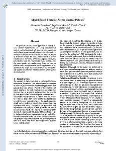
3. PULSE WIDTH MODULATOR In spite of fluctuations in the output load and the input voltage, the output DC power must be maintained in order to achieve the desired voltage. DC-DC converters can be easily controlled with a familiar technique known as PWM (Pulse Width Modulation) by switching on and switching off durations (ton and toff). PWM is a method to provide controlled power to electrical equipment with the help of practical switches. The average output value is controlled with the help of a duty cycle. The longer the switch is kept on; the more is the power supplied to the output load. The main advantage of PWM is that the power dissipation is low [9]. Saw-tooth voltage is utilized to control the output DC voltages in the DC-DC converters. As shown in Figure 7, a repeating saw-tooth voltage (a) has been modeled to produce a PWM (b). Namely, in the PWM, switching frequency is kept constant while duty is varied to achieve the desired O/P control voltage signal. When the saw-tooth voltage is lesser than the duty signal, the switch control signal is high. When the duty signal is lesser than the saw-tooth voltage, the control signal is in off state [10, 11].
Fig. 6 Buck boost converter design
(b)
(a)
Fig. 7 (a) SawTooth Waveform; (b) Modulated Output
52
ENGINEERING MODELLING 24 (2011) 1-4, 49-56
K. Nithiyananthan, A.K Loomba: MATLAB/Simulink based speed control model for converter controlled DC drives
3.1 Cascading with buck converter The cascaded model of buck converter and DC motor is shown in Figure 8. Using a pulse width modulator, one can very easily control the speed of motor. The speed of the motor is adjusted with the duty value to get the desired output armature current and rotor speed.
3.2 Cascading with boost converter The cascaded model of boost converter and DC motor is shown in Figure 9.
The boost converter is employed here to step up the input voltage; the duty cycle varies the output speed and armature current of the separately excited DC motor.
3.3 Cascading with buck boost converter The cascaded model of boost converter and DC motor is shown in Figure 10. The buck boost model needs an additional multiplier as the polarity of the output voltage is negative compared to the input voltage.
Fig. 8 Buck converter cascaded with DC
Fig. 9 Boost converter cascaded with DC
Fig. 10 Buck boost converter cascaded with DC motor ENGINEERING MODELLING 24 (2011) 1-4, 49-56
53
K. Nithiyananthan, A.K. Loomba: MATLAB/Simulink based speed control model for converter controlled DC drives
4. SIMULATION RESULTS The input field voltage and armature voltage has been varied to control the rotor speed. The following graphs can be inferred by varying load torque (Figure 11) and voltages (Figure 12) value.
Fig. 11 Variation of load torque
Figure 11 shows the variation in speed and armature current with wavering of the load torque. As the load increases, speed of the motor gradually decreases while armature current increases.
Fig. 12 Variation of armature voltage
Figure 12 shows the result of variation in armature voltage with respect to time. As armature voltage is increased, the angular speed of the motor increases. Though the inrush current will be very high as the Va is increased, armature current will be lower. On increasing the field voltage the field current increases consequently. There is a decline in the velocity of the motor as well as the armature current as shown in Figure 13. 54
ENGINEERING MODELLING 24 (2011) 1-4, 49-56
K. Nithiyananthan, A.K Loomba: MATLAB/Simulink based speed control model for converter controlled DC drives
Fig. 13 Variation of field voltage
5. CONCLUSION In this paper, a comprehensive analysis of DC drive system has been performed by using MATLAB/ Simulink. The simulation model which is implemented in a modular manner under MATLAB/Simulink environment allows that many dynamic characteristics such as phase currents, voltages, rotor speed, and
mechanical torque can be effectively considered. Furthermore, the performance analysis of variation of the load torque, field voltage and armature current has been achieved. It is seen that the desired smooth and accurate speed control has been achieved. The results show that MATLAB paired with Simulink is a good simulation tool for modeling and analyzing converter controlled DC motor drives.
ENGINEERING MODELLING 24 (2011) 1-4, 49-56
55
K. Nithiyananthan, A.K. Loomba: MATLAB/Simulink based speed control model for converter controlled DC drives
5. REFERENCES [1] D.P. Kothari and I.J. Nagrath, Electric Machines, 3rd edition, Tata McGraw-Hill Book Company, New Delhi, 2008. [2] N. Mohan, T.M. Undeland and W.P. Robbins, Power Electronics: Converters, Applications and Design, 3rd edition, John Wiley & Sons, Inc., Hoboken, 2003. [3] P. Pillay and R. Krishnan, Modeling, simulation, and analysis of permanent-magnet motor drives Part II: The brushless DC motor drive, IEEE Trans. on Industry Applications, Vol. 25, pp. 274–279, 1989. [4] A. Rubai, A. Ofoli and M. Castro, dSPACE DSPbased rapid prototyping of fuzzy PID controls for high performance brushless servo drives, IEEE Industry Applications Conference, 41st IAS Annual Meeting, Tampa, pp. 1360–1364, 2006. [5] S.T. Karris, Introduction to Simulink with Engineering Applications, Orchard Publications, 2006. [6] R. Carlson, M. Lajoie-Mazenc and C.D.S. Fagundes, Analysis of torque ripple due to phase commutation in brushless DC machines, IEEE Trans. on Industry Applications, Vol. 28, pp. 632– 638, 1992.
[7] S.K. Safi, P.P. Acarnley and A.G. Jack, Analysis and simulation of the high-speed torque performance of brushless DC motor drives, IEE Proc. - Electric Power Applications, Vol. 142, No. 3, pp.191–200, 1995. [8] J. Figueroa, C. Brocart, J. Cros and P. Viarouge, Simplified simulation methods for polyphase brushless DC motors, Mathematics and Computers in Simulation, Vol. 63, pp. 209–224, 2003. [9] Ch.-W. Hung, Ch.-T. Lin and Ch.-W. Liu, An efficient simulation technique for the variable sampling effect of BLDC motor applications, IECON 2007, 33rd Annual Conf. of the IEEE, Industrial Electronics Society, pp. 1175-1179, 2007. [10] R.N. Tuncay, Z. Erenay, M. Yilmaz and O. Ustun, Rapid control prototyping approach to fuzzy speed control of brushless DC motor, Proc. Int. Conf. on Electrical and Electronics Engineering ELECO’03, Bursa, Ed. R.N. Tuncay, 2003. [11] Ch.-L. Xia, P.J. Guo, T.N. Shi and M.H. Wang, Speed control of brushless DC motor using genetic algorithm based fuzzy controller, Proc. Int. Conf. on Intelligent Mechatronics and Automation - ICIMA 2004, Chengdu, pp. 460464, 2004.
PRETVARA^EM KONTROLIRAN MODEL KONTROLE BRZINE ZA DC POGON UTEMELJEN NA MATLAB/SIMULINK SA@ETAK Glavni cilj prikazanog istra`ivanja je razviti pretvara~em kontroliran precizan model kontrole brzine za DC pogon. Naime, kontrola brzine je jedan od najzna~ajnih aspekata DC motora. On se mo`e lako kontrolirati pomo}u raznih tipova DC-DC pretvara~a. Ovaj ~lanak se odnosi na široki krug DC motora i pretvara~a. Projektirani model je zna~ajno razvijen rabe}i prostorno modeliranje motora i pretvara~a pomo}u programa Simulink. Mo`e se rabiti kod motornih pogona i transportnih aplikacija. ^lanak omogu}ava široki uvid u subjekt istra`ivanja i usko razumijevanje svrhe i efekata raznih parametara. Klju~ne rije~i: kontrola brzine, pretvara~, DC pogon, DC motor, MATLAB, Simulink.
56
ENGINEERING MODELLING 24 (2011) 1-4, 49-56