Abstract. This paper describes a new compression/decompression methodology for using an embedded processor to test the other components of a ...
Matrix-Based Test Vector Decompression Using an Embedded Processor Kedarnath J. Balakrishnan and Nur A. Touba Computer Engineering Research Center Department of Electrical and Computer Engineering University of Texas, Austin, TX 78712-1084 Email: {kjbala,touba}@ece.utexas.edu Abstract This paper describes a new compression/decompression methodology for using an embedded processor to test the other components of a system-on-a-chip (SoC). The deterministic test vectors for each core are compressed using matrix-based operations that significantly reduce the amount of test data that needs to be stored on the tester. The compressed data is transferred from the tester to the processor's on-chip memory. The processor executes a program which decompresses the data and applies it to the scan chains of each core-under-test. The matrix-based operations that are used to decompress the test vectors can be performed very efficiently by the embedded processor thereby allowing the decompression program to be very fast and provide high throughput of the test data to minimize test time. Experimental results demonstrate that the proposed approach provides greater compression than previous methods.
1. Introduction Systems-on-a-chip (SoCs) have become ubiquitous nowadays because of the advances in technology that make it possible to build complete systems containing different types of components (called cores) on the same chip. Typically, these cores are pre-designed and preverified by their vendors and the SoC designer has to just integrate them in the system. Each core typically comes with its own set of test vectors and hence the SoC on the whole ends up with a large set of test vectors. This translates into two major issues that can affect the testing of such SoCs – (i) increase in tester memory requirements since the entire set of test vectors for all the components need to be stored on the tester and transferred to the chip during testing and (ii) longer test application times since the time required to test a chip depends on the amount of test data that needs to be transferred and the bandwidth of the channel connecting the test to the chip. These problems result in higher test costs. One solution to this problem is test data reduction by compressing the test vectors. The compressed data is stored on the tester and transferred to the SoC where an on-chip decompressor decodes the test data and applies it to the appropriate core. The decompression can be done in hardware using a dedicated decoding circuitry or in software by an embedded processor. Several compression techniques based on lossless compression codes have been proposed in the literature for reducing the test volume. The Burrows-Wheeler transformation and a modified run length encoding are used in [Yamaguchi 97]. A modified version of Huffman encoding is used in [Jas 99a] to compress deterministic test sets. The modification is made to minimize the bits needed for the codewords so that the hardware required for decompression is simpler. In
Proceedings of the 17th IEEE International Symposium on Defect and Fault Tolerance in VLSI Systems (DFT’02) 1063-6722/02 $17.00 © 2002 IEEE
[Jas 98], a variable-to-block run length encoding is used to compress a fully specified test set, and a cyclical scan chain is used to decompress the test data. Golomb codes were proposed in [Chandra 00] to enhance the compression in the above scheme. A variable-to-variable-length code called a frequency-directed run-length (FDR) code has been proposed in [Chandra 01]. Schemes that can be implemented using an embedded processor have been proposed in [Jas 99b] and [Maleh 01]. In [Jas 99b], each test vector is divided into blocks and only those blocks that are different from the preceding vector are stored. Test vectors are then constructed on the fly by a program running on the embedded processor and sent to the appropriate core. In [Maleh 01], encoding is done on optimally reordered test vectors based on geometric shapes. The decoding algorithm required to get back the original test vectors by this method is very complex and is a limitation of the approach. This paper presents an efficient compression/ decompression scheme for test vectors with unspecified bits based on matrix operations. The decompression algorithm is much simpler than earlier works and an embedded processor present in the SoC can efficiently implement it with a relatively fewer number of processor instructions.
2. Proposed Scheme The proposed scheme is based on the decomposition of a matrix into two vectors based on a relation that we define below. The operation A⊕� B between two Boolean vectors A = [a1, a2, a3…an] and B = [b1, b2, b3… bn] where ai, bi ∈ {0,1} is defined as shown in Fig. 1. Note that this is very similar to matrix multiplication except that the elements in the product matrix are defined differently (ai⊕ bi instead of ai• bi). This helps increase the chances of decomposition since the XOR operation puts less constraints on the inputs than AND by making the equations linear. a1 a2
~ A⊕ B =
~ ⊕b
1
a1⊕b1 a1⊕b2 a1⊕b3 a1⊕b4 a1⊕b5 a1⊕b6 a1⊕b7 a1⊕b8
b2 b3 b4 b5 b6 b7 b8
a2⊕b1 a2⊕b2 a2⊕b3 a2⊕b4 a2⊕b5 a2⊕b6 a2⊕b7 a2⊕b8 a3⊕b1 a3⊕b2 a3⊕b3 a3⊕b4 a3⊕b5 a3⊕b6 a3⊕b7 a3⊕b8
a3
=
a4 a5
a4⊕b1 a4⊕b2 a4⊕b3 a4⊕b4 a4⊕b5 a4⊕b6 a4⊕b7 a4⊕b8 a5⊕b1 a5⊕b2 a5⊕b3 a5⊕b4 a5⊕b5 a5⊕b6 a5⊕b7 a5⊕b8 a6⊕b1 a6⊕b2 a6⊕b3 a6⊕b4 a6⊕b5 a6⊕b6 a6⊕b7 a6⊕b8
a6
a7⊕b1 a7⊕b2 a7⊕b3 a7⊕b4 a7⊕b5 a7⊕b6 a7⊕b7 a7⊕b8
a7
a8⊕b1 a8⊕b2 a8⊕b3 a8⊕b4 a8⊕b5 a8⊕b6 a8⊕b7 a8⊕b8
a8
Figure 1. Matrix Operation A⊕ �B
1 1
0 0 0 0 0 0 0 1 0 0 0 0 0 0 0 0 0 0 0 0 0 0 0 1 0 0 0 0 0 0
1
0 0 0 0 0 0 0 0 0 1 0 0 0 0 0 ... ... ... ... ...
a1
v1
a2
v2
a3
v3
..
=
..
..
..
b8
v64
... 0
0 0 0 0 0 0 1 0 0 0 0 0 0 0 1
Figure 2. Set of Linear Equations for the Decomposition
Proceedings of the 17th IEEE International Symposium on Defect and Fault Tolerance in VLSI Systems (DFT’02) 1063-6722/02 $17.00 © 2002 IEEE
In this way, an n×n matrix can be represented with the two vectors A and B and the operation A⊕� B. This decomposition can be realized by solving a simultaneous set of equations in the variables ai, bi. If and only if a solution of this set of equation exists, the given matrix can be decomposed. The set of equations is represented in the matrix format (Ax = b) as shown in Fig. 2. This is derived by writing the coefficient for the variables ai,bi as 1 if those variable exists in the constraint, otherwise as 0. For example, the element in the first row and first column of the original matrix is a1⊕ b1 (Fig. 1) and the corresponding equation for this is the first row in Fig. 2. We propose a compression scheme for test vectors based on the above. This involves writing n2 bits of the test vector as an n×n matrix M. The matrix M is then decomposed by solving the set of linear equations. Although the decomposition in not always possible, the unspecified bits in the test vectors increase the chances of decomposition. This is because only equations for the specified bits of the test vector need to be satisfied. The more unspecified bits there are, the fewer the number of equations and hence less constraints on the variables. Several different heuristics can be applied to form the matrix M that needs to be decomposed from the given set of test vectors. These vary according to the complexity of the decoding process. Three of these are discussed below. 2.1 Single Size Decomposition (SSD) This is the simplest method to form the matrix M and also the easiest to decode. The first n2 bits of the test vector are written as an n×n matrix with the first n bits being the first row of the matrix and the next n bits the next row and so on and so forth as illustrated in Fig. 3. Original Test Vector
M=
0011X100001X11000100...
0011 X100 001X 1100
Figure 3. Formation of Matrix M with n = 4 The choice of the size of the matrix (i.e., n) would depend on the word size of the processor. If the matrix M thus formed cannot be decomposed for the next n2 bits of the test vector, we store the first n bits as they are (i.e. uncompressed) and then proceed with the algorithm for the next n2 bits after that. Hence we need one bit at the start of every set of bits to indicate whether the bits are compressed or not. 2.2 Multiple Size Decomposition (MSD) A simple optimization of the method in Sec. 2.1 would be to try to form the matrix M with three different sizes. The largest size is tried first since that gives the maximum compression. If the matrix for the largest size is not decomposable, then the next size is tried and so on. If none of the three sizes of the matrix are decomposable, then the next set of m bits are left uncompressed and the algorithm is tried on the successive bits of the test vector. Two additional bits are needed to encode the four cases that can occur indicating whether the succeeding bits have been compressed by any of the three sizes or they are left uncompressed. 2.3 Multiple Vector Decomposition (MVD) The matrix M can also be formed from multiple test vectors as illustrated in Fig. 4. In this case, each row of the matrix would correspond to a different test vector. This is a better
Proceedings of the 17th IEEE International Symposium on Defect and Fault Tolerance in VLSI Systems (DFT’02) 1063-6722/02 $17.00 © 2002 IEEE
alternative than the earlier ones since there is usually a lot of similarity between test vectors due to the structural relationship among the faults that are detected by these test vectors. Furthermore, the test vectors can be ordered in an optimal way such that the chances of decomposition of the matrix are increased. Test Vector 1 Test Vector 2 Test Vector 3 Test Vector 4
0011 X100 0XX1 110X
X100001X11000100... 001X11000100X110... 10X000100111X001... 1110100000X00011...
M
Figure 4. Formation of Matrix M using MVD For example, a hill climbing approach could be used to get a good ordering of test vectors for compression. In the hill climbing approach, initially the given order of test vectors is used to calculate the compression. Two vectors are then randomly exchanged and the new compression calculated. If the compression is better, the new order is saved; else the old order maintained. This process is continued until no better compression is obtained for a specific number of exchanges. A limiting factor of this method is that the decoding is more complex and the partial test vectors constructed after decoding each matrix cannot be directly applied to the core-undertest until a sufficient number of matrices have been decoded to get the complete test vector.
3. Decompression Using an Embedded Processor
Memory
Core 2
Embedded Processor
scan_enable Scan Chain 1 Scan Chain 2
Core 1 Core 3
MISR
Tester
Memory I/O Controller
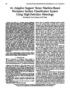
An embedded processor present in the SoC can be used to efficiently decompress the compressed data and send it to the core-under-test (CUT). This is illustrated in Fig. 5. An external tester supplies the compressed data while a simple software program running on the embedded processor decodes the test data.
Scan Chain N
Core Under Test
Figure 5. Example of Test Architecture The tester loads the test data into a specific set of addresses of the system memory through the memory I/O controller. The tester also writes to a given location to indicate the end of the current test vector. The processor reads the data from the corresponding locations in memory and decompresses it accordingly. Depending on the number of scan chains in the core, the
Proceedings of the 17th IEEE International Symposium on Defect and Fault Tolerance in VLSI Systems (DFT’02) 1063-6722/02 $17.00 © 2002 IEEE
processor either sends the data directly to the core or stores it back to memory so that it can apply the data to the core when it has a sufficient amount of decompressed test data. If the end of the test vector is reached, it sends an instruction to apply a capture cycle to capture the response into the scan chain. The response is shifted out into a multi-input shift register (MISR) for compaction as the next test vector is shifted into the core. In general, the speed at which test data is transferred to the SoC by the tester will be much lower than the operating frequency of the embedded processor. Two potential problems could arise because of this discrepancy. If the processor is able to process the written data before the tester loads new data into the memory location, appropriate NOPs need to be inserted into the decompression program to make sure that next time the processor reads the memory location it has the new data. The second problem arises if the tester overwrites new data to a memory location before the processor is able to process the old data in it. This can be taken care of by inserting NOPs at appropriate places into the tester program to slow it down. decoder( ) { read number of test vectors (M) read the three matrix sizes n1 , n2 , n3 read number of uncompressed bits m while(vector_ processed < M){ read_memory_ location(); check the first two bits: case 00:{ A[1..n] = next n1 bits B[1..n] = next n1 bits for(i = 1, n 1){ M[i][0.. n1 ] = A[i] ⊕B[0.. n 1]; Write_Core(M[i][0.. n1 ]); } case 01:{ A[1.. n2 ] = next n 2 bits B[1.. n2 ] = next n 2 bits for(i = 1, n 2){ M[i][0.. n2 ] = A[i] ⊕B[0.. n 2]; Write_Core(M[i][0.. n2 ]); } case 10:{ A[1.. n3 ] = next n 3 bits B[1.. n3 ] = next n 3 bits for(i = 1, n 3){ M[i][0.. n3 ] = A[i] ⊕B[0.. n 3]; Write_ Core( M[i][0.. n3 ] ); } case 11:{ M[0..m] = next m bits Write_ Core ( M[0..m]); } if end of test vector reached { Write_ Core (Capture); vectors_processed++; } } }
Figure 6. Pseudo-Code for Decompression Algorithm
Proceedings of the 17th IEEE International Symposium on Defect and Fault Tolerance in VLSI Systems (DFT’02) 1063-6722/02 $17.00 © 2002 IEEE
In the case of multiple size decomposition (MSD), if the three different sizes, n1, n2, n3 and the number of bits left uncompressed, m, are chosen carefully (i.e. depending on the word size of the embedded processor and the number of scan chains in the core-under-test), the decompression and the overall test time can be reduced considerably. The sizes should be such that 2n1 + 2, 2n2 + 2, 2n3 + 2, and m + 2 are all multiples of the word size of the processor. Figure 6 shows the pseudo code of the decompression algorithm for this heuristic. Since the first two bits denote which of the four cases to apply to the next set of bits, we check for them and proceed accordingly. The macro Write_Core will depend on the number of scan chains in the core and the width of the bus connecting the processor to the core.
4. Experimental Results The compression scheme proposed in this paper targets cores in a SoC. Experiments were performed on the larger ISCAS-89 benchmark circuits [Brglez 89]. Test cubes with 100% coverage of detectable faults were generated using an ATPG tool for each circuit. Unspecified input assignments were left as X’s for better compression. Static compaction of the test cubes was performed, and reverse fault simulation was done to remove superfluous test cubes. The three heuristics described in Sec. 2 were used to compress the test set. The results obtained are shown in Table 1. The percentage compression is computed as: Percent Compression = (Original Bits – Compressed Bits)/ (Original Bits) x 100 Table 1. Compression Obtained on Benchmark Circuits Circuit
Scan Size
Test Vectors
s5378 s9234 s13207 s15850 s38417 s38580
214 247 700 611 1664 1464
119 147 239 120 95 131
Origina l Bits 25466 36309 167300 73320 158080 191784
SSD Comp. Percent Bits Comp. 14501 43.1 22355 38.4 62130 62.9 33847 53.8 89063 43.7 92667 51.7
MSD Comp. Percent Bits Comp. 12254 51.9 18234 49.8 33038 80.3 25112 65.8 69850 55.8 68812 64.1
MVD Comp. Percent Bits Comp. 10390 59.2 16888 53.5 33470 80.0 23552 67.9 69556 56.0 66838 65.2
Table 2. Comparison with Other Techniques Circuit
Original bits
s5378 s9234 s13207 s15850 s38417 s38580
25466 36309 167300 73320 158080 191784
[Jas 99b] Compressed Percent Bits Compression 14550 42.9 21303 41.3 26108 84.4 27171 62.9 103328 34.6 94840 50.55
[Maleh 01] Percent Compression 51.6 43.5 85.0 60.9 46.6 -
Proposed Scheme Compressed Percent Bits Compression 10390 59.2 16888 53.5 33470 80.0 23552 67.9 69556 56.0 66838 65.15
The first column is the circuit name. The next three columns show the number of scan elements, the number of test vectors, and the total bits in the test set. The fifth and sixth columns show the compressed test set size and the corresponding percentage compression when single
Proceedings of the 17th IEEE International Symposium on Defect and Fault Tolerance in VLSI Systems (DFT’02) 1063-6722/02 $17.00 © 2002 IEEE
size decomposition (with size n = 8) is used. The next two columns show the compression obtained using multiple size decomposition with sizes n1 = 16, n2 = 8, n3 = 4 and m = 10. The last two columns show the results of compression obtained using multiple vector decomposition with n, the number of vectors taken at a time equal to 8. The hill climbing approach described in Section 2.3 was used to optimally reorder the test vectors with the exchange limit set as 100. From the results, it can be seen that the multiple vector decomposition scheme has the best compression ratio but it is also the most complex to decode among the three methods discussed. The test application time will be the longest in this case since the test vectors need to be constructed completely and stored in the system memory before they can be applied to the core. The multiple size decomposition heuristic obtains a good amount of compression and is relatively simpler to decode. The choice of which method to apply will depend on the operating conditions of the test architecture. If test application time is critical, multiple size decomposition is a better alternative. In Table 2, we compare our results with [Jas 99b] and [Maleh 01]. The results shown for [Jas 99b] were calculated using their method for the same test set as ours. As seen from the table, our method results in better compression for all the circuits except s13207.
5. Conclusions In this paper, an efficient test vector compression method was proposed that utilizes the power of an embedded processor present on the chip to help in testing the cores in the SoC. The decompression is performed in software by a program running on the embedded processor. Hence both test storage and test time is reduced. The compression scheme described in this paper is very simple as compared to other methods proposed earlier.
Acknowledgements This material is based on work supported in part by the National Science Foundation under Grant No. MIP-9702236 and in part by the Texas Advanced Technology Program under Grant No. 003658-0644-1999.
References [Brglez 89] Brglez, F., D. Bryan, and K. Kozminski, “Combinational Profiles of Sequential Benchmark Circuits,” Proc. of International Symposium on Circuits and Systems, pp. 1929-1934, 1989. [Chakrabarty 97] Chakrabarty, K.,Murray, B. T., Liu, J., and Zhu, M., “Test Width Compression for Built-In SelfTesting,” Proc. International Test Conference, pp. 328-337,1997. [Chandra 00] Chandra, A., and Chakrabarty, K., “Test Data Compression for System-on-a-chip using Golomb Codes,” Proc. of IEEE VLSI Test Symposium, pp. 113-120, 2000. [Chandra 01] Chandra, A., and Chakrabarty, K., “Frequency-Directed Run-Length Codes with Application to System-on-a-chip Test Data Compression,” Proc. IEEE VLSI Test Symposium, pp. 42-47, 2001. [Jas 98] Jas, A., and Touba, N. A., “Test Vector Decompression via Cyclical Scan Chains and its Application to Testing Core-Based Designs,” Proc. International Test Conference, pp. 458-464, 1998. [Jas 99a] Jas, A., Dastidar, J. G., and Touba, N. A., “Scan Vector Compression/Decompression Using Statistical Coding,” Proc. IEEE VLSI Test Symposium, pp. 114-120, 1999. [Jas 99b] Jas, A., and Touba, N. A., “Using an Embedded Processor for Efficient Deterministic Testing of Systemon-a-Chip,” Proc. IEEE Int. Conf. on Computer Design (ICCD), 1999. [Maleh 01] El-Maleh, A., Al-Zahir,S., and Khan, E., “A Geometric Primitives Based Compression Scheme for Testing Systems-on-a-Chip,” Proc. IEEE VLSI Test Symposium, pp. 540-59,2001. [Yamaguchi 97] Yamaguchi, T., Tilgner, M., Ishida, M., and Ha, D. S., “An Efficient Method for Compressing Test Data,” Proc. International Test Conference, pp. 191-197, 1997.
Proceedings of the 17th IEEE International Symposium on Defect and Fault Tolerance in VLSI Systems (DFT’02) 1063-6722/02 $17.00 © 2002 IEEE