We describe the design of Maya and the simulation mechanism brie y. Some of the performance results on architectural simulation with di erent memory.
Maya: A Simulation Platform for Parallel Architectures and Distributed Shared Memories Divyakant Agrawal
Manhoi Choy
Hong Va Leong
Ambuj K. Singh
Department of Computer Science University of California at Santa Barbara Santa Barbara, CA 93106
Abstract
Maya is a simulation platform for evaluating the performance of parallel programs on parallel architectures with di�erent memory coherence protocols. It uses the communication library PVM to ensure portability. Rapid prototyping of di�erent memory protocols of varying degrees of coherence is possible and the impact of these protocols on the performance of application programs can be studied. We describe the design of Maya and the simulation mechanism brie y. Some of the performance results on architectural simulation with di�erent memory coherence protocols are presented. Parallel discrete event simulation techniques are adopted for the execution-driven simulation of parallel architectures. Keywords: modeling of parallel architectures, parallel and distributed simulation, parallel programming, weak memories
0
1
Introduction
Recent interest in high performance computing has led to a greater need for adequate simulation tools and models for evaluating parallel architectures and parallel programs on these architectures. Several simulation systems have been developed [AHH88, CLN90, EKKL90, BDCW91, DGH91, RHL+ 93] and based on the granularity of the simulator, the simulation techniques used in these simulators can be broadly classi ed into three categories: trace-driven or statistical simulation, functional or instruction level simulation, and execution-driven simulation with direct execution. Trace-driven simulation systems [AHH88, BKW90, EKKL90] have been used for a long time. They are fast but su�er from a low accuracy. Functional simulators such as the ASIM simulation system [CLN90] provide a high degree of accuracy of a simulated execution with respect to the real-time execution. However, these simulators are slow with a slowdown generally in the range of two to three orders of magnitude. Execution-driven simulators, on the other hand, represent a compromise between the two extremes. These simulators sacri ce the speed of trace-driven simulations for greater accuracy. The representatives of this class are the Tango system from Stanford [DGH91], the Proteus system from MIT [BDCW91], and the Wisconsin Wind Tunnel [RHL+ 93]. These simulation systems provide a reasonable level of accuracy between simulated and real-time executions with a moderate slowdown of about one to two orders of magnitude. In this paper, we describe an execution-driven simulation system, Maya1, that is being developed. In trace-driven simulators, a program trace of a parallel program is generated by running the parallel program either on a sequential machine, on the target parallel machine, or on another parallel machine. The trace contains all the required accesses to the shared memory by the execution threads of the parallel program. This trace is used as an input to the simulator which in turn simulates the target architecture or a protocol (e.g., a distributed shared memory protocol [LH89]) running on the target architecture. The input traces can also be generated statistically from some benchmarks or some measured distributions. These simulators do not actually execute the parallel program or the protocol. The input program trace determines the runtime dependency of the simulated program statically. As a result, dynamic dependencies, which may arise in the program due to the target architecture or the protocol, cannot be simulated. Since the simulator does not incur the latencies due to the actual execution of the program or the protocol, the overheads in trace-driven simulation are low. In fact, the simulation may even take less time than the actual execution. Functional simulators mimic every single step of the target architecture down to the instruction level, or even to the micro-code level. They therefore represent the software speci cation of the underlying architecture. Though they are extremely accurate, the overhead in mimicking every single step in the execution is often quite high, and this renders them impractical in the performance evaluation of useful parallel programs. In addition, each parallel architecture requires a timeconsuming analysis and development of a new simulator. Execution-driven simulation has achieved a considerable amount of success as a compromise of the above two approaches. The high cost of simulating every single instruction is avoided by executing parallel programs directly on the host machine. In order to simulate the execution of parallel programs on a target architecture, timing information must be maintained for both 1
Maya in Sanskrit means \illusion".
1
computation and communication. Only accesses that are of interest to the simulation are considered and their e�ects are integrated into the state of the simulation. Complete program dependencies and program output are reproduced. Tango [DGH91], an example of such a simulator, models each simulated user process by a Unix process and uses semaphores for process synchronization. Shared accesses to memory are replaced with function calls to the simulator, which maintains all the timing and scheduling information. The simulator then selects the access or simulation event with the smallest simulated time and carries out the relevant computation or communication. The original implementation of Tango is only available on SGI and DEC workstations and is not portable. Proteus [BDCW91] uses lightweight threads to reduce the overhead of context switching and data copying. All data of user processes are encapsulated into a single large address space and shared accesses are replaced by function calls to the simulator during the pre-processing phase. Both Tango and Proteus implementations are intended for sequential or shared memory architectures. The Wisconsin Wind Tunnel (WWT) [RHL+ 93] is a solitary example of an execution-driven simulation system that can be executed on a distributed memory machine. The system distinguishes between local and shared memory accesses by exploiting the ECC hardware of CM-5. In particular, shared accesses to the memory that is mapped on a di�erent processor result in a trap. This approach is good since locally mapped shared memory accesses incur no overhead. The main drawback with the WWT is that it can only be run on a CM-5 and is not portable to other parallel architectures. Maya is a parallel programming system which supports execution-driven simulation on distributed memory architectures. Inspired by the success of WWT in exploiting multiple processors to speed up the simulation, Maya is intended to work primarily on a distributed memory platform. It is based on the PVM communication library [Sun90], and can be ported to any environment that supports Unix and PVM. We have so far ported Maya to a network of Sun workstations and the Intel Paragon. Maya is intended to radically change the process of parallel program development on MIMD architectures. In particular, parallel program designers have a tendency to use the low-level message passing interface in MIMD environment at the user level to get around the ine�ciencies resulting from traditional distributed shared memory implementations. Our approach is to encourage the programmers to develop programs in the shared memory paradigm, which is considered simpler for parallel programming, by providing alternative consistency notions of memory at the lower level. Thus a major thrust of Maya has been the examination of di�erent protocols for shared memories, especially the implementations of memories that are not sequentially consistent [Lam79]. These weaker memories have a lower latency and when used correctly, can enhance the performance of parallel programs [ABHN91, AH90, DSB86, GLL+ 90, LS88]. Maya is capable of simulating the execution of a number of such memories including causal memory [ABHN91], and pipelined random access memory [LS88]. Preliminary evaluation results for a number of user applications appear in [Maya93]. This paper is organized as follows. An overview of the design of Maya is presented in Section 2. In Section 3, the simulation environment and the modeling of parallel architectures are discussed. Section 4 contains some architectural simulation results and a performance comparison with Proteus. We conclude with a brief discussion in Section 5.
2
2
An Overview of Maya
Maya is designed to be a versatile tool for parallel programming with a variety of features. First, it is capable of simulating a target parallel architecture on a di�erent host machine. Second, it is useful as a programming environment for rapid prototyping of parallel programs. Finally, it is intended as a test-bed for experimenting with protocols for di�erent kinds of shared memories. To provide these features, Maya operates principally in two di�erent modes: the simulation mode and the native mode. The simulation mode performs a simulated execution of a parallel program on the target architecture with a speci c memory coherence protocol. In the native mode, the target and the host architectures are identical and no simulation is needed. In either mode, it is easy to replace one memory coherence protocol by another.
User Process 0
Data Placement Module
User Process 1
User Process n-1
Synchronization
Coherence
Module
Module
MEMORY
SUBSYSTEM
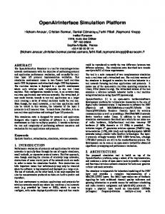
Figure 1: The logical organization of Maya The logical organization of Maya is depicted in Figure 1. Users of Maya write their programs by using an extension of C that enables processes to share variables. Shared variables are declared explicitly and currently we restrict such sharing to the primitive types in C as well as to arrays composed of these primitive types. A pre-processor (currently under design) scans the user parallel program to identify the shared variables and arrays. These are allocated in the memory subsystem and the memory allocation is done with pages of a xed size. The pre-processor also translates the accesses to the shared variables in the user program to standard C macro calls supported by the memory subsystem in Maya. The memory subsystem is composed of three modules: the data allocation module, the synchronization module, and the coherence module. The data allocation module is responsible for allocating space in the memory subsystem for the shared data and cooperating with other memory subsystems to partition the data. The aim is to reduce communication overhead in the sharing of the data and to minimize the e�ect of false sharing. At present, the data allocation algorithm is relatively straightforward. A round-robin manager-based placement strategy is adopted. On the average, each node manages 1=nth of the total number of shared pages 3
in an n-node system. Several user-controlled directives, which allow the declaration of possible con icting data items involved in concurrent accesses, are provided to reduce false sharing. The pre-processor translates data placement directives into data placement calls. The synchronization module provides primitives for process synchronization: both explicit and implicit. Explicit synchronization includes barriers and locks , which can be detached from the issues of data coherence. Implicit synchronization refers to the synchronized starting of user processes and the initialization of shared variables. The coherence module enforces the required level of coherence for shared data by executing the speci c memory coherence protocol when shared data is accessed. This is the main ingredient of a distributed shared memory protocol. user
user
user
user
user
user
Memory Subsystem
Memory Subsystem
Memory Subsystem
Communication Subsystem
Communication Subsystem
Communication Subsystem
COMMUNICATION
NETWORK
Communication Subsystem Memory Subsystem user
user
Figure 2: The physical organization of Maya Figure 2 illustrates the physical organization of Maya. We assume that the host architecture consists of a set of processors each with its private memory (referred to as a node) connected by a network. The Maya environment on each node comprises of three layers: the user program or application layer, the memory subsystem layer, and the communication subsystem layer. The memory subsystem in Maya acts as an interface between the user processes and the network to support shared memory in a distributed environment. As discussed above, the accesses to the shared variables result in macro calls to the memory subsystem. Currently the interface between the users and the memory subsystem is based on messages. The memory subsystem executes the underlying distributed shared memory protocol by communicating with the memory subsystems on other nodes. The distributed static manager scheme [LH89] is implemented as the base case memory protocol (referred to as \atomic memory" protocol in this paper) for both comparison and testing purposes. The memory subsystem in Maya is extensible. Currently, we have developed a 4
library to support distributed shared memory protocols based on sequentially consistent memory, , and pipelined random access memory [Maya93]. The primary responsibility of the communication subsystem is to facilitate communication among the memory subsystems, which cooperate with one another to implement distributed shared memory. The communication subsystem in Maya is based on the message passing library PVM [Sun90]. Since PVM is available on most distributed memory architectures, Maya can be supported on a variety of hardware platforms. Another advantage of using PVM is that it can be used in a network of heterogeneous Unix compatible machines since PVM uses an external message passing standard. Although PVM imposes certain bu�er management and daemon computation overhead, we consider fast prototyping and portability more important. We are investigating alternatives such as asynchronous I/O to eliminate these overheads. The communication subsystem in Maya can be con gured to simulate a target parallel architecture on the host machine. As a simulator, the view of Maya changes slightly and is discussed in the next section. causal memory
3
Architectural Simulation
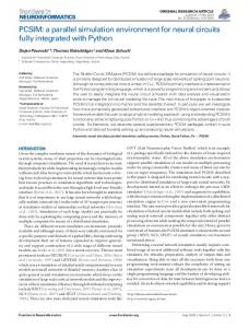
Maya can be con gured as a simulation environment for parallel architectures. Functioning as a simulator, Maya automatically transforms both the parallel user program and the memory coherence protocol into simulation programs using a set of macros. Monitoring codes are inserted for each communication event in the coherence protocol and cycle counting codes are added to maintain timing information in the simulated environment. A number of useful statistical information can be obtained from Maya in the simulation mode. Examples include the number of requests per user, the number of messages sent due to the coherence protocol, the hit and miss counts for shared memory accesses, and the total simulated execution time. The total simulated execution time can be broken down into components such as the time due to the execution of the user processes and the memory subsystem, and the time for which user processes are idle (waiting for synchronization or for results from shared accesses). The con guration of Maya in the simulation mode is shown in Figure 3. Scheduling of user processes residing at the same node is handled by the memory subsystem, which cooperates with the network simulator (called the network manager henceforth). The network manager, currently implemented as a centralized process, executes a parallel discrete event simulation over the host machine nodes and network. Two major components exist in the network manager: message delay model and communication event scheduler. The message delay model is used to determine the arrival time of a message sent over the target architecture communication network. The communication event scheduler schedules the delivery of messages and resolves any deadlock. Maya simulation ensures repeatability: repeated execution of the same user program with the same input will yield exactly the same output and simulated execution time. This feature is useful for rapid prototyping of parallel programs by making it easier for debugging timing anomalies. In the following subsections, we will discuss the target parallel architecture modeling, the event scheduling mechanism, and the network contention modeling in greater detail.
5
user
user
user
user
user
user
Memory Subsystem
Memory Subsystem
Memory Subsystem
Communication Subsystem
Communication Subsystem
Communication Subsystem
HOST
MACHINE
COMMUNICATION
Message Delay Model
NETWORK
Communication Event Scheduler
Target Machine Network Simulation Module
Figure 3: Architectural simulation in Maya 3.1
Modeling Parallel Architectures
Several models exist for parallel architectures and computations [FW78, Gib89, Val90, CKP+ 93]. The traditional PRAM models [FW78, Gib89] are not accurate enough for useful modeling since many important architectural aspects such as communication overheads are missing. The bulksynchronous parallel computer model [Val90] views a computation as a sequence of supersteps. In each superstep, each component of the system is allocated a task consisting of local computation, message transmission, and message reception. These components are synchronized at the end of regular intervals of xed time units to see if the allocated superstep has completed. If it has, the system proceeds to the next superstep. Otherwise, the next interval is allocated to the un nished superstep. This model is simple to implement, but it is only appropriate for parallel programs that conform to the model. The LogP model [CKP+ 93] characterizes a parallel architecture by the communication delay L, the communication overhead o, the communication bandwidth g , and the number of processors P . Various aspects of the architecture are approximated by these four parameters. Our architectural simulation model is similar to that of the LogP model. Parameters used in Maya can be categorized to model the delay, overhead and bandwidth. The number of processors P is not explicitly used in our model. In Maya, the characteristics of the parallel architecture are modeled by two sets of parameters. The rst set of parameters captures the computational aspects of the parallel architecture, whereas the second set delineates the communication aspects. The parameters on computational speed are categorized based on instruction groups such as integer addition, integer multiplication, oating 6
point addition, oating point division, procedure call, etc. Cycle counting statements are inserted into the user program to maintain the timing information for local computation. The simulation clock is advanced accordingly as the simulation proceeds. For faster simulations, these timing statements are not added after every statement of the user program. Instead, they are added before blocks of local accesses. To cater for the communication delay between nodes, we require the simulation model designer to provide a function netdelay that models the target communication network after taking the network congestion level into account. In the current prototype of Maya, the network manager in Figure 3 schedules the message delivery events using netdelay since it has the complete knowledge of all communication events occurring between nodes. 3.2
Event Scheduling
In order to mimic the execution of the parallel program on the target architecture, events and processes need to be scheduled correctly. This execution is modeled in terms of a set of simulation events which correspond to the accesses to shared variables and the resulting message transmission, delivery, and processing in the memory subsystems. Maya schedules all these events in the same order as they would appear in a real execution on the target architecture by tagging each event with a timestamp from the simulation clock and executing them in timestamp order. Simulation events local to a process are executed in timestamp order. Non-local simulation events such as transmissions and deliveries of messages are scheduled by the network manager. Logically, all internodal messages are sent to their destination node via the network manager, which maintains a queue of relevant events ordered by their timestamps. Based on the message transmission timestamps from senders, the network manager computes the timestamp of a message delivery event by adding the network delay estimated by the network delay model and redirects the message to the receiver. This scheme results in a consistent interface for both the native and the simulation mode. While the manager process is responsible for the scheduling of communication events among memory subsystems, memory subsystems are responsible for the scheduling of events on the node. These events include shared access requests from user processes and the receipt of messages from other memory subsystems. Each memory subsystem maintains an ordered queue for these simulation events in the same manner as the manager does. For events due to messages from other memory subsystems, the arrival timestamps of the events are supplied by the manager. For events due to shared access requests, a special function time mapping is used to determine the arrival timestamps. Function time mapping models the speci c scheduling algorithm employed by the operating system on the target architecture. It takes the local timestamp of an event which is supplied by the user process and the relevant past history of the execution on the node and returns a modi ed local timestamp. This modi ed timestamp is the real scheduling time of the event after taking operating system scheduling overheads and delays into account. Di�erent scheduling schemes require di�erent time mapping functions. For the applications we are simulating, there is only a single user process residing at each node. Consequently, function time mapping simply models the overheads and delays of a memory subsystem. Event scheduling follows the framework of parallel discrete event simulation [Fuj90]. Owing to the asynchrony of the simulated system, one has to make sure that events are scheduled in the same order as in the actual execution. This can be guaranteed by observing the input waiting rule and the 7
output waiting rule as in the conservative approach for parallel discrete event simulation [CM79]. In Maya, the input waiting rule is enforced by requiring the manager to wait until it receives a message from each memory subsystem. The output waiting rule is enforced by requiring the manager to schedule a message only when the simulation clock has advanced to the send time of the message. Conservative approaches in parallel discrete event simulation may lead to deadlocks. One way to avoid deadlocks is to ush all the communication channels periodically with null messages [CM79]. In Maya, the deadlock resolution scheme is attached to the centralized manager. The deadlock resolution scheme is a combination of deadlock avoidance and deadlock detection. The manager keeps track of the number of outstanding messages of each memory subsystem. When the number of outstanding messages drops to zero, the manager calculates the largest time T such that no memory subsystem will receive another messages with send timestamp smaller than T . The value of T is then broadcast to all memory subsystems. Memory subsystems are allowed to schedule local events only if they are issued before time T . If T is updated and broadcast frequently, this scheme tends to avoid deadlocks before they actually occur. Furthermore, if deadlock does occur, the number of outstanding messages among the memory subsystems will eventually become zero. Subsequently, the manager will be able to detect the deadlock and resolve it by sending another value of T . To compute the largest possible value of T , lookahead techniques [LL90] are adopted. In particular, suppose the smallest send timestamp of all the messages the manager has received is t and the minimum message delay on the target architecture is d. It can be shown that when the manager nds that the number of outstanding messages is zero, no memory subsystem will receive any message before time t + d. Consequently, T can be taken as t + d. Our scheduling scheme is further optimized in the case where successive shared accesses are separated by a large block of local access and computation. In this situation, the application process is setup to report the largest timestamp before which it will not make any shared access. Event scheduling on other nodes may be accelerated based on this additional information.
3.3
Modeling Contention and Communication Delay
It is important to take the congestion level of the target communication network into account in order to obtain a realistic estimate of the parallel program performance. To simplify the modeling process, we assume the existence of a function netdelay that takes into account the contention level in the network and computes the message delay. Function netdelay takes an event of message transmission and returns the time at which the message should be received by the receiver. For some network contention models, the arrival time of a message depends not only on the current network contention, but also on the tra�c in the immediate future. The function netdelay is allowed to return ?, if there is inadequate information to determine the arrival time of a message. Eventually, when su�cient information becomes available, an arrival time is returned. The amount of information needed to estimate the receipt time of a message varies for di�erent accuracy levels. In our prototype, we assume that the scheduling of messages on most networks is independent of the local computation on the nodes of the target machine. Therefore, a separate network manager can be used for the scheduling of messages during simulation. In the current prototype of Maya, the ideal delay of a message is modeled as the sum of the sender overhead, the receiver overhead, and the transmission delay. Sender and receiver overheads 8
are assumed to be constant. Transmission delay is modeled as a linear function proportional to the length of the message. The actual delay of a message is the ideal delay plus a factor due to network contention. A collision-based model is introduced to model the e�ect of contention. This model is useful for communication networks that exhibit the behavior of message collisions. Let the propagation interval of a message transmitted at time t be the interval [t; t + d) where d is the calculated transmission delay of the message. A collision is said to occur between two or more messages transmitted over a common channel if their propagation intervals overlap. We handle collision by rescheduling messages whose propagation intervals overlap. In our collisionbased model, when a collision occurs, the message with the smallest transmission time succeeds and all the others are re-transmitted. Note that this results in recomputation of the propagation intervals for the delayed messages when they are re-transmitted. A penalty e is charged to delayed messages so that they are re-transmitted e units of time after the end of the propagation interval of the rst message. The value of e depends on the communication network being used. This collision-based model can be easily implemented in the context of Maya and can be used to model a point-to-point network or an Intel Paragon mesh under moderate network tra�c by setting e = 0. However, our model may underestimate the e�ect of collision on some networks. For example, on Ethernet, it is possible that the message with the smallest transmission time t is also delayed if another message is transmitted within time t plus the round trip propagation delay on Ethernet. Fortunately, the probability of this occurring is almost zero as the round trip propagation delay on Ethernet is very small.
4
Experimental Results
The rst version of Maya includes a library of coherence protocols: atomic memory, causal memory, pipelined random access memory , and some of their variations. Several application programs including the Gaussian elimination and matrix inversion (Gaussian inverse), all pairs shortest path, the traveling salespersons problem, the Jocabi iterative synchronous linear equation solver [ABHN91], and the Cholesky factorization from the SPLASH benchmark [SWG91] have been used. Preliminary results of the performance of some of these coherence protocols and application programs when used in the native mode are obtained from a network of Sun workstations and from an Intel Paragon [Maya93]. In this section, results from the simulation mode are presented. These results are based on one user application: a Gaussian inverse algorithm, two kinds of coherence protocol: atomic memory and causal memory, and two di�erent architectures: a network of Sun workstations and an Intel Paragon. The results obtained from the simulation mode are compared with the results obtained from the native mode. Finally, the performance of Maya is evaluated by comparing it with another simulation tool Proteus [BDCW91] and by varying the degree of concurrency. 4.1
Results of Architectural Simulation
The input to the Gaussian inverse problem is a matrix of size N 2 N and the output is the inverse of the input matrix. The Gaussian inverse algorithm in our experiment is composed of an input stage, a computation stage consisting of N phases separated by barriers, and an output stage. The input and output stages correspond to the reading of the input matrix and writing of the nal 9
matrix and the time for this part of the execution is omitted from all our results. The N rows of the matrix are evenly assigned to the n participating processes. In phase i, the process in charge of row i selects one of its rows as a pivot row. All the processes cache this row and use it for their local computation on their rows. Due to the use of barriers and variable sharing patterns in the Gaussian inverse algorithm, coherence protocols weaker than atomic memory can be used. We choose to use atomic memory and causal memory in our experiments. In the case of atomic memory, all reads and writes are blocking, i.e., the user processes issuing these operations are blocked until the operations are successfully performed. Copies of the memory may migrate dynamically and are kept track of by a distributed directory [LH89]. In the case of causal memory, each memory subsystem keeps a copy of the shared memory. Reads to the shared memory are served locally. Writes to the shared memory are broadcast and performed in a causal order2 . 400 3503 + 300 250 sec. 200 150 100 50 2
450
Actual execution time 3 Simulated time +
+ 3
3
350+ 3
3 +
sec. 300
250
+
4 5 6 number of processes
+ n
7
3 +
200 150
8
) Causal memory on Paragon
2
3
450
3
sec. 300
+
250
+ 3
4 5 6 number of processes
+ 3 n
n
7
8
Actual execution time 3 Simulated time +
400+ 3 350
3
4 5 6 number of processes
+ 3
b
Actual execution time 3 Simulated time +
+ 3
+ 3
) Causal memory on workstations
a
400 + 3503 300 250 sec. 200 150 100 50 2
Actual execution time 3 Simulated time +
400
7
3
3
+
+
200 150
8
) Atomic memory on Paragon
2
3
4 5 6 number of processes
n
7
) Atomic memory on workstations
c
d
Figure 4: Native mode versus simulation mode for Gaussian inverse with N = 500 A network of Sun workstations is used as the host machine in our simulation experiments. The target machines being simulated are the same network of Sun workstations and an Intel Paragon. The application program is run with n user processes. In a network of Sun workstations, an Ethernet 2
This causal order re ects the happen-before relations [Lam78] between the read and write operations to shared memory locations.
10
8
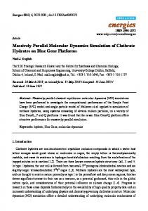
is used to connect a set of Sparc LX workstations. Each user process and the memory subsystem it communicates with are assigned to one workstation so that there are a total of n workstations. In the Intel Paragon, a set of nodes are connected by a two-dimensional mesh of communication channels. Each node consists of two i860 microprocessors, one for computation and one for communication. In executing Gaussian inverse, a partition of 2n nodes is used and user processes and memory subsystems are assigned to di�erent nodes. With the use of communication microprocessors, the communication delay between nodes that are far away on the mesh is not much di�erent from the communication delay between adjacent nodes on the mesh. To obtain the necessary parameters for simulating the two target machines, we have written simple benchmark programs to estimate the speeds of the processors for local computation, the communication overheads when using PVM as the underlying communication interface, and the bandwidths of the networks. Figure 4 compares the actual execution times and simulated times running Gaussian inverse for N = 500 with n equal to 2; 4; 6; and 8. As shown in gures 4a and 4b, the simulated times obtained for causal memory match the actual execution time within a small percentage on both a Paragon3 and a network of workstations. In the case of atomic memory, the simulated times obtained also agree with the actual execution time on the Paragon (Figure 4c). However, the simulated times obtained in the case of a network of workstations are relatively low compared with the actual execution time (Figure 4d). One particular reason for this is that activities due to internal processes of PVM are not modeled. Consequently, the costs of some operating systems activities such as context switching are underestimated. The e�ect is more signi cant in atomic memory because read and write operations are blocking and the errors of underestimated activities are accumulated. 4.2
Performance of Maya
In Figure 5, we compare the times needed to simulate Gaussian inverse for N = 500 using Maya and Proteus with n user processes. We choose to compare with Proteus because it is available on Sparc and it is claimed to be one of the fastest simulator in its category. Since Proteus only provides atomic coherence protocol, atomic memory is used in this experiment. The design of Proteus is quite similar to that of Maya. User programs are compiled into assembly language programs, which are then pre-processed to convert shared access into traps to the Proteus simulator. Cycle counting statements are also inserted during pre-processing. The resulting programs are linked with the simulation programs of Proteus to obtain an executable le. Note that the pre-processing in Proteus is more machine dependent as it uses assembly language programs. For the simulation with Maya, n + 1 Sparc LX workstations connected by an Ethernet are used so that each user and its corresponding memory subsystem are assigned to one workstation and the manager process is assigned to a separate workstation. The target machine being simulated has the same architecture, a network of Sun workstations connected by an Ethernet. For simplicity, communication delay under no contention is estimated by the formula k1 + k2 3(message length), for some constants k1 and k2. For the simulation with Proteus, a single Sparc LX workstation is used to perform the simulation. The communication network of the target machine being simulated is a fully connected bidirectional network. To model such a network, Proteus also estimates commu3
Some native mode results are not available at this time due to a recent system upgrade on Paragon
11
Proteus 3 Maya, simulation mode + Maya, native mode 2
7000 6000 5000 sec.
3
3
3
3
3
3
4000 3000 2000 1000 0
+
+
+
+
+
2
+
3 +
2
2
2
2
2
2
2
3
4 5 6 number of processes n
7
8
Figure 5: Comparison between Maya and Proteus nication delay by evaluating an analytical formula. Consequently, the computational requirements due to the estimation of communication delays are similar in Maya and Proteus and the simulation results should re ect the performances of the two simulators in terms of their e�ciencies in simulating the chosen coherence protocol and application program. Also, for fair comparison, the same optimization level is used for compilations and statistical data outputs are disabled in both systems. It turns out that Proteus can only be used for the simulation of Gaussian inverse for N as large as about 500 on the workstations we are using. This is probably due to the large space requirement of simulating large number of processes on a single machine. On the other hand, Maya can be used for N over 1000. Figure 5 compares the performance of Maya and Proteus for for N = 500. Proteus is about 14 to 17 times slower than the native mode while Maya is about 3 to 11 times slower than the native mode. (Note that Proteus uses one Sparc LX workstation for each simulation but the number of workstations used in case of Maya varies with n.) We also conducted the experiment on di�erent problem sizes and discover that for problem sizes larger than 500, the ratio between the speed of the simulation program and the original user program remains roughly the same. However, for the case of Proteus, we expect that the simulation will be much slower as the additional computation due to both the original user program and the simulation is not distributed. Figure 6 shows the speedup of performing simulation in Maya by varying the number of processors used in the host environment. In this experiment, we x the number of user processes to 32. We assume that each user process resides on a di�erent processing unit of the target machine and there is a memory subsystem corresponding to each user. We simulate the same Gaussian inverse algorithm using 1 or more workstations. Since the bottleneck of the simulator is in the manager 12
180003 17500 17000 16500 16000 sec.15500 15000 14500 14000 13500 13000 12500 1
Maya's execution time
3
3
3
3
3 3 3
2
3 4 5 6 number of workstations
7
8
Figure 6: Simulating using various number of machines (N = 500; n = 32) process, only moderate speedup is obtained as more workstations are used. 7000
Maya's execution time
6000
3
5000
3
sec. 4000
3
3000
3
2000
3
1000
3 3
2
4
3 6 8 10 number of user processes
n
12
14
Figure 7: Simulating varying number of user processes using 2 workstations (N = 500) The slowdown of performing simulation in Maya with 2 workstations is depicted in Figure 7. As the number of user processes is increased, the number of memory subsystems and the number of processors in the target machine are also increased correspondingly. The slowdown is almost linear to n, which is expected as more computation and communication are needed to simulate larger number of user processes.
13
5
Discussion and Future Work
In this paper we have presented the system overview of Maya which is a simulation platform for evaluating parallel architectures and distributed shared memory protocols. Maya is an executiondriven simulator and can be ported to a variety of distributed memory architectures. It can be used for rapid prototyping of parallel programs employing the shared memory paradigm. Furthermore, Maya facilitates shared memory parallel program development based on di�erent notions of memory consistency. We feel that this is a better approach of developing parallel programs instead of exposing the low-level message passing paradigm to the users. Finally, users can experiment with a variety of parallel architectures which can be simulated easily through Maya. Currently, Maya is installed on a network of Sun workstations and on an Intel Paragon. We are also redesigning certain aspects of the current architecture of Maya. The message-based interface between user processes and the memory subsystem is being coupled tightly by integrating the memory subsystem in the virtual memory of the user processes. This approach will result in minimal overhead for user accesses to the shared memory that is mapped locally at the user's node. Non-local memory accesses will result in software traps which will trigger the underlying distributed shared memory protocol. Another issue that we are investigating is to decentralize the current implementation of the network manager. One approach would be xed partitioning of the single network manager to a set of network managers. The other approach would be to implement a fully distributed network manager. Future work includes further research into weak memory systems and their impacts on parallel programs and the class of parallel programs that can bene t from weaker memories.
References [ABHN91] Mustaque Ahamad, James E. Burns, Phillip W. Hutto, and Gil Neiger. Causal memory. In Proceedings of the 5th International Workshop on Distributed Algorithms, pages 9{ 30. LNCS, October 1991. [AH90]
S.V. Adve and M.D. Hill. Weak ordering - A new de nition. In Proceedings of the 17th Annual International Symposium on Computer Architecture, pages 2{14. IEEE, May 1990.
[AHH88]
A. Agarwal, J. Hennessy, and M. Horowitz. Cache performance of operating system and multiprocessing workloads. ACM Transactions on Computer Systems, 6(4):393{ 431, November 1988.
[BDCW91] Eric A. Brewer, Chrysanthos N. Dellarocas, Adrian Colbrook, and William E. Weihl. Proteus: A high-performance parallel-architecture simulator. Technical Report MIT/LCS/TR-516, MIT, Laboratory for Computer Science, September 1991. [BKW90] A. Borg, R.E. Kessler, and D.W. Wall. Generation and analysis of very long address traces. In Proceedings of the 17th Annual International Symposium on Computer Architecture, pages 270{279, 1990. [CKP+ 93] D. Culler, R. Karp, D. Patterson, A. Sahay, K.E. Schauser, E. Santos, R. Subramonian, and T. von Eicken. LogP: Towards a realistic model of parallel computation. In 14
Proceedings of the Fourth ACM SIGPLAN Symposium on Principles and Practice of
, pages 1{12, 1993.
Parallel Programming
[CLN90]
D. Chaiken, B.H. Lim, and D. Nussbaum. Memo#13, August 1990.
. ALEWIFE Systems
[CM79]
K.M. Chandy and J. Misra. Distributed simulation: A case study in design and veri cation of distributed programs. IEEE Transactions on Software Engineering, 5(9):440{ 452, September 1979.
[DGH91]
H. Davis, S.R. Goldschmidt, and J. Hennessy. Multiprocessor simulation and tracing using Tango. In Proceedings of the 1991 International Conference on Parallel Processing, volume II, pages 99{107, August 1991.
[DSB86]
Michael Dubois, Christoph Scheurich, and Fay�e A. Briggs. Memory access bu�ering in multiprocessors. In Proceedings of the 13th Annual International Symposium on Computer Architecture, pages 434{442, May 1986.
ASIM User Manual
[EKKL90] S.J. Eggers, D.R. Keppel, E.J. Koldinger, and H.M. Levy. Technique for e�cient inline tracing on a shared-memory multiprocessor. In Proceedings of the 1990 ACM SIGMETRICS Conference on Measurement and Modeling of Computer Systems, pages 37{47, May 1990. [Fuj90]
R. Fujimoto. Parallel distributed discrete event simulation. , 33(10):30{53, October 1990.
Communications of the
ACM
[FW78]
S. Fortune and J. Wyllie. Parallelism in random access machines. In Proceedings of the 10th Annual ACM Symposium on the Theory of Computing, pages 114{118, 1978.
[Gib89]
P.B. Gibbons. A more practical PRAM model. In Proceedings of the 1st Annual ACM Symposium on Parallel Algorithms and Architectures, pages 158{168, 1989.
[GLL+ 90] K. Gharachorloo, D. Lenoski, J. Laudon, P. Gibbons, A. Gupta, and J.L. Hennessy. Memory consistency and event ordering in scalable shared-memory multiprocessors. In Proceedings of the 17th Annual International Symposium on Computer Architecture, pages 15{26. IEEE, May 1990. [Lam78]
Leslie Lamport. Time, clocks, and the ordering of events in a distributed system. , 21(7):558{565, July 1978.
Communications of the ACM
[Lam79]
Leslie Lamport. How to make a multiprocessor computer that correctly executes multiprocess programs. IEEE Transactions on Computers, 28(9):690{691, September 1979.
[LH89]
Kai Li and Paul Hudak. Memory coherence in shared virtual memory systems. Transactions on Computer Systems, 7(4):321{359, November 1989.
[LL90]
Y.B. Lin and E.D. Lazowska. Exploiting lookahead in parallel simulation. IEEE Transactions on Parallel and Distributed Systems, 1(4):457{469, October 1990.
[LS88]
Richard J. Lipton and Jonathan S. Sandberg. PRAM: A scalable shared memory. Technical Report CS-TR-180-88, Princeton University, Department of Computer Science, September 1988. 15
ACM
[Maya93] Evaluating weak memories with Maya. Technical report, 1993. [RHL+ 93] Steven K. Reinhardt, Mark D. Hill, James R. Larus, Alvin R. Lebeck, James C. Lewis, and David A. Wood. The Wisconsin Wind Tunnel: Virtual prototyping of parallel computers. In Proceedings of the 1993 ACM SIGMETRICS Conference on Measurement and Modeling of Computer Systems, pages 48{60, May 1993. [Sun90]
V. Sunderam. PVM: A framework for parallel distributed computing. , 2(4):315{339, December 1990.
Concurrency:
Practice and Experience
[SWG91] [Val90]
J.P. Singh, W.D. Weber, and A. Gupta. SPLASH: Stanford parallel applications for shared memory. Technical report, Stanford, Computer Systems Laboratory, 1991. Leslie G. Valiant. A bridging model for parallel computation. , 33(8):103{111, August 1990.
ACM
16
Communications of the