Dec 7, 1993 - IBM T.J. Watson Research Center Department of Computer Science ... Calls by application processes to message-passing routines are trapped by ..... as A + B L where A is a startup cost, L is the message length and B is the ...
A Distributed Memory LAPSE: Parallel Simulation of Message-Passing Programs � Phillip M. Dickens ICASE NASA Langley Research Center Hampton, VA 23681
Philip Heidelberger
y
David M. Nicol
z
IBM T.J. Watson Research Center Department of Computer Science P.O. Box 704 The College of William and Mary Yorktown Heights, NY 10598 Williamsburg, VA 23185
December 7, 1993
Abstract
As massively parallel computers become increasingly available, users' interest in the scalability of their parallel codes is growing. However, such computers are in high demand, and access to them is restricted. In this paper we develop techniques that allow one to use a small number of parallel processors to simulate the behavior of a message-passing code running on a large number of processors. Such methods will allow a user to performance tune a code for massive parallelism before actually using large numbers of processors. Other potential applications include parallel simulation of large distributed systems driven by directly executing application code, and high-performance simulations of network designs driven by directly executing application code. We distribute simulation processes and application processes among multitasking processors. Calls by application processes to message-passing routines are trapped by simulator processes, which are responsible for scheduling application process execution, for simulating message transfers through the massively parallel communication network, and for simulating each application process's virtual time advance. Our methods are being implemented in a tool, LAPSE (Large Application Parallel Simulation Environment) for the Intel Paragon multicomputer. This paper reports on our initial experiments with LAPSE.
Research supported by NASA contract number NAS1-19480, while the authors were in residence at the Institute for Computer Applications in Science & Engineering (ICASE), NASA Langley Research Center, Hampton, VA 23681. y This work was performed while this author was on sabbatical at ICASE. z This work was performed while this author was on sabbatical at ICASE. It is also supported in part by NSF grant CCR-9201195 . �
1 Introduction The notion of \scalability" pervades current research in parallel processing. Given a parallel algorithm or computer program and a particular class of computer architecture, one wishes to know how performance will behave as the problem size and the number of processors increases. For any number of reasons, a code that achieves good performance on a small number of processors may not on many processors. Users are interested in knowing if this happens, and why it happens. One may also wish to know how the application will perform under di�erent releases of the operating system (with di�erent overheads), di�erent network architectures, or how well a new network design performs. The most direct way of answering these questions is to execute the code using many processors on the software and hardware of interest. However, this isn't always practical. Massively parallel machines are very expensive, and are shared among many users. It can be di�cult, expensive, or infeasible for a user to acquire the full resources of a massively parallel machine on a regular basis. However, smaller numbers of processors of such a machine may be routinely available. This small number of processors can then be used to emulate the code running on the larger system, and to predict the time it would have taken to execute the application on the larger system. Similarly, the code of the parallel multicomputer could be emulated on a network of interconnected workstations. Additionally, designers of large distributed systems could make use of parallelized simulation of the network, driven by executing application code, as could designers of new communication networks. This paper shows how to couple parallelized simulation of the large machine's communication network with direct execution techniques [5, 6, 8, 9, 11]. Given N application processes whose performance on N processors is sought, we use n < N processors to both execute the application and simulate its timing behavior. Each physical processor is assigned some number of application processes (virtual processors, or VPs) and a simulator process; these are all multitasked. Alternatively, the n processors may be partitioned into a set dedicated to network simulation, and one to application execution. In either case the simulator processes control the execution of the application processes, and together with other simulator processes emulate message tra�c. The message tra�c is generated directly by actually running the application processes|all interactions of the application processes with the communication network are trapped and handled by simulator constructs. The simulators also quantify delays su�ered by application processes due to interrupts signaling receipt of a message. The simulator processes' fundamental job is to determine how simulation time advances as a function of the actual application process execution and the simulated network behavior. This approach promises fairly rapid evaluation of a code's scalability and the possibility of monitoring network behavior|albeit simulated behavior|in a way that is not normally possible on actual codes. An interesting prospect is the integration of such a tool within a performance monitoring system such as Pablo [16]. Several other projects use direct execution of application processes to drive simulations of multiprocessor systems. Among these we nd two pertinent characteristics, (i) the type of network being simulated, and (ii) whether the simulation is itself parallelized. Table 1 uses these attributes 1
to categorize relevant existing work, and our own tool, LAPSE, the Large Application Parallel Simulation Environment, that we are currently implementing on the Intel Paragon multicomputer. Tool LAPSE MaxPar[4] Proteus[2] RPPT[5] Simon[8] Tango[7] WWT[17]
communication simulator message-passing network parallel shared memory (no cacheing) serial cache-coherent shared memory serial message-passing network serial message-passing network serial cache-coherent shared memory serial cache-coherent shared memory parallel
Table 1: Direct Execution Simulation Tools. Among most current simulators other than our own, simulation of cache-coherency protocols are an important concern. LAPSE is being implemented on our own lab's machine, an Intel Paragon[10], which does not support shared virtual memory. Coherency protocols complicate the simulation problem considerably, but are a facet LAPSE need not deal with. However, existing work has identi ed context-switching overhead as a key performance consideration, and it is one that directly a�ects us. As much as an order of magnitude improvement has been observed when a directexecution simulator uses its own light-weight threads constructs to accelerate context-switching (for small grain sizes). At the time of this writing it is not clear whether LAPSE will be able to map (without modifying the kernel) application processes distinctly into its own memory space, providing each with the illusion of a private address space. Until we do, LAPSE's performance is hostage, in part, to the scheduling decisions and costs of the Paragon's operating system, OSF-1 Unix. It should also be noted that some of these simulators are part of extensive tool sets meant to span architectures, e.g., Proteus and RPPT. At present LAPSE is focused entirely on high performance simulation of parallel codes on the Intel Paragon. However, its methods ought to transfer directly to any other message-passing oriented architecture. The Wisconsin Wind Tunnel (WWT) is to our knowledge the only multiprocessor simulator that uses a multiprocessor (the CM-5) to execute the simulation. It is worthwhile to note the di�erences between LAPSE and the WWT. The rst is a matter of purpose. LAPSE's primary goal is to support scalability and performance analysis of Paragon codes (although it has other applications, noted earlier). The WWT is a tool for cache-coherency protocol researchers, being designed to simulate a di�erent type of machine than its host. A second di�erence is a matter of lookahead, the ability of a conservative parallel simulation to predict its future behavior. In a cache-coherent system, a processor may interact with the communication network on any cache miss, or may have its cache a�ected by a write at any time by another processor. The lookahead is apparently poor. The WWT deals with this by keeping things in close synchrony. The WWT exploits an assumption 2
that any communication between processors requires at B � 100 number of cycles. Application object code is altered to cause WWT application processes to synchronize every B cycles. Any communication is deferred until the next barrier with the assurance that the barrier occurs before the communication can have a�ected its recipient. (This method of synchronization is a special case of the YAWNS [12, 14] protocol.) The WWT ignores any network contention by assuming that the latency of every message is xed, and known. By contrast, Paragon processors are less tightly coupled. In a cache-coherent setting any memory reference might generate a network event; in a message-passing setting only an explicit call to a message-passing subroutine can in uence network behavior. This fact allows a less rigid approach to synchronization. In particular, many large numerical programs alternate between a long computation phase where no communication occurs and a communication-intensive phase. Because of better lookahead possibilities, LAPSE can avoid synchronization during long periods of network idleness whereas the WWT cannot. The lookahead available in LAPSE comes from the observation that, in many applications, the execution path is independent of timing behavior. In such a case, the application code can be executed well in advance of actually simulating the timing. If the execution path is not independent of timing, lookahead can still be obtained provided there is a lower bound on the operating system overhead required to send or receive a message. Finally, the WWT uses a customized operating system that cleverly exploits CM-5 idiosyncrasies to recognize misses in the simulated cache. LAPSE is designed to run purely in application mode, as its intended environment (a government lab) is not conducive to customized kernels. Individual elements of LAPSE have been proposed before, e.g., parallelized direct execution, and di�erent simulators for di�erent granularities. Our contribution is to show how distributed memory programs can be simulated on a parallel machine using direct execution, with the ability to model the communication network to any desired level of detail. This combination of features makes LAPSE unique among its peers.
2 An Overview A parallel program for a distributed memory machine is comprised of M application processes, distributed among N � M processors. Most parallel programs are constructed so that N = M , an equivalence we presently assume. We assume the mapping is static. Application processes communicate through message passing using explicit calls to system library routines. For example, the csend call in the Intel library sends a message. The calling application passes arguments de ning the message type (a user-de ned integer), the message base address and length, the process id and processor id of the recipient. Control is returned to the application as soon as the entire message has left the processor. crecv is called to receive a message; arguments are the message type, base address to place the message, and maximum message length. Control is returned to the application process once the message is received. irecv is an asynchronous version of crecv. If the receive routine is called before the anticipated message arrives, the incoming message will transfer directly from the network into the speci ed location in user space. Otherwise the message transfers 3
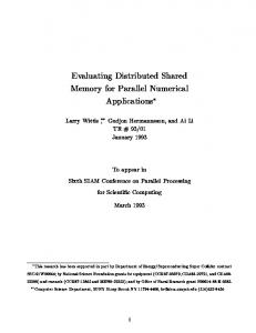
from the network into a system bu�er; a subsequent receive call copies the message into user space. Figure 1(a) illustrates how an application process views time. It runs for a period, then calls a system message-passing routine to send or receive a message. The message transaction is complete upon return of control to the application. The time the system spends handling messages is invisible to the application. An application process knows about execution durations, e.g., process 1 can measure or predict durations a ? 0, c ? b, and e ? d under the assumption that it is not interrupted. If we can assume that such durations are independent of network activity (again assuming lack of interruptions, a facet we do deal with), these durations give us the lookahead we need for parallel simulation. Interrupt durations and message-passing overheads are determined in part by the network state, as illustrated in Figure 1(b). In Figure 1(b), a message is sent from process 1 to process 2 starting at time a. At time a, control is passed to the operating system on processor 1. Because of the operating system overhead required to prepare the message for transmission over the network, control is not returned to application process 1 until time b. The message begins coming out of the network on processor 2 at time f , thereby interrupting process 2, which was in the middle of an execution block. At this point the operating system on processor 2 gains control to handle the interrupt. After the message has been completely received by the operating system, control is returned to application process 2 (at time g ). When process 2 nally reaches the code (at time h) that explicitly receives the message (in this case copying it from a system bu�er to user space) an additional overhead is incurred; this message receipt overhead is completed at time i at which time process 2 begins executing again. By contrast, process 1 reaches its receive statement (at time c) before the message from process 2 arrives. The arriving message moves directly into user space, and a copy from system space to user space is avoided. Application process 1 continues execution after the receive has been completed (at time d). The application processes are unaware of these timing details. It falls to the application simulator to assign virtual times to event times a, b, c, and so on, as a function of the execution durations reported by the application processes, an evaluation by a network simulator of message-passing delays, assumed operating system overheads for message-passing and interrupt handling, and a model of how message-passing activity a�ects the execution of application processes. Figure 2 gives an overview of LAPSE's structure. To use LAPSE an application must be recompiled with LAPSE macros that redirect application message-passing calls to LAPSE routines. (LAPSE currently supports applications written in C. Fortran support is planned.) Object code for these routines are linked to the application, becoming resident in user space. Application calls to message-passing routines are redirected to LAPSE interface routines. The interface routines receive the speci c details of the transfer from the calling arguments (e.g., the processor id to which the message is directed and the actual data to be sent); in addition they extract timing information (e.g., the uninterrupted execution block lengths shown in Figure 1) needed by the simulator process. The execution block lengths are obtained by passing the application's assembly code through a parser. The parser modi es the original assembly code by inserting instruction counting code into the application code. During a LAPSE run, both the application code and the instruction counting code are executed, thereby providing the interface routines with an accurate count re ecting the 4
execute
process 1
receive
execute
send ab
0
execute
c d receive execute
execute
process 2
h i
0
execute j k
(a) Application View
execute
process 1
a
b send
0
0
f
d
receive
interrupt
execute
process 2
c
execute
execute g
receive h
send i
j
k
(b) Network View
Figure 1: Application and Network views of parallel application timings number of application process instructions executed since the last message-passing call. Timing information is then derived from these counts. The interface routines are responsible for transforming the process and processor id given by the application into those assigned by LAPSE . The interface routines perform the actual message transfers (to other interface routines), report the speci cs of the transfer to the simulator process, and eventually return control to the application processes under direction of the simulator process. A simulator process is comprised of an application simulator and a network simulator. The former inserts message descriptions into the latter, the latter delivers message descriptions and timings to the former. The simulator processes communicate and synchronize among themselves directly. We have speci cally separated the application and network simulation functions to permit the easy use of di�erent network simulators. For example, we have one Paragon network simulator that is simple and fast because it assumes no contention; we have a more complex one that captures contention by modeling message transmission on a packet-by-packet basis. The interface between the application and network simulators is simple, allowing integration of additional network simulators.
5
processor
processor Network Simulator
Network Simulator
Application Simulator
Application Simulator
Interface
Interface
Interface
Interface
Appl.
Appl.
Appl.
Appl.
Communication Network
messages between network simulators messages from interface routines to application routines messages between interface and application simulator
Figure 2: LAPSE�s communication structure
3 Technical Issues In this section we address some technical issues, including process remapping, process timing, application/simulator interface, and simulation synchronization.
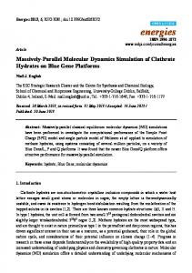
3.1 Process Id Remapping The current version of LAPSE assumes that the application under study assigns a single process to every processor. This is a very common feature of the SPMD (Single Program Multiple Data) codes that dominate multiprocessing (especially among Intel users since only recently has multitasking been supported). By default, LAPSE maps virtual processors (VPs) to actual processors in such a way that if a p � q actual mesh of processors is used to simulate a virtual P � Q mesh, then each actual processor is assigned a contiguous region of (P=p) � (Q=q ) VPs. This is illustrated by Figure 3, where a virtual 4 � 8 mesh has been partitioned for simulation on a physical 1 � 4 mesh. If communication among VPs is localized, then this mapping helps to keep much of the message tra�c on-processor.
6
i,j 0,0
1,0
2,0
3,0
4,0
5,0
7,0
6,0
Virtual Processor 0,1
1,1
2,1
3,1
4,1
5,1
6,1
7,1
0,2
1,2
2,2
3,2
4,2
5,2
6,2
7,2
0,3
1,3
2,3
3,3
4,3
5,3
6,3
7,3
0,0
0,1
0,3
0,2
Physical Processors
Figure 3: Partitioning of a virtual 4 � 8 virtual mesh for simulation on a 1 � 4 actual mesh
3.2 Process Timing Each application process must provide the LAPSE simulator with estimates of the time it requires to execute between calls to message library routines. While the Paragon does provide a hardware wallclock with microsecond resolution, its operating system (OSF-1 Unix) does not yet provide process timing information with anywhere near that accuracy. Thus, as described earlier, LAPSE estimates execution time by modifying the application object code to count the number of instructions executed. (The counter is updated only at basic block boundaries, a technique also used in [2, 17, 7]. The overhead to implement the instruction counting is 5 instructions per basic block.) This modi cation does not require compiler support, we use lexical analysis of the intermediate assembler code. While more elaborate timing models are possible, our timer assumes that each instruction takes the same amount of time to execute. While such counts are exact (in the absence of intervening system calls) this method does not exactly quantify a number of e�ects (except possibly in an average case sense). Such e�ects include cache hit ratios, translation lookaside bu�er hit ratios, instructions that take di�ering times to execute, instruction parallelism as is found in superscalar architectures, nor are timings for embedded calls to system routines (e.g., for I/O) provided. These are de ciencies that can, in principle, be corrected, although adding, for example, a detailed cache simulator adds substantial overhead to the simulator. It should also be recognized that many of these de ciencies are common to other direct execution simulators. To obtain accurate timing of the application, the operating system overhead for sending and receiving messages needs to be properly accounted for. LAPSE currently estimates such operating system overheads. For example, the overhead (in instructions) to execute a csend can be modeled as A + B � L where A is a startup cost, L is the message length and B is the cost per byte. Estimates of A and B can be obtained by measurements of the operating system. In principle, it would also be possible to instrument the operating system itself with the instruction counting code and to run this instrumented code as part of the simulator. This would eliminate the need for using 7
estimated path lengths, however, it requires access to the operating system source code as well as authorization to run the modi ed kernel.
3.3 Application/Simulator Interface LAPSE traps all references to message library routines by recompiling the application code with a le of macros that redirect message library calls to LAPSE routines. These LAPSE interface routines are linked into the same memory address space as the application process. The LAPSE routine identi es the call as an event. Parameters of the event are collected, e.g., event type (read, write, probe), number of instructions executed since the last event by this process, characterization of the the message event (e.g., message id, starting memory location, length, recipient processor(s), recipient process id). For a message send event the interface routine translates the process and processor ids, and issues the message. Since the LAPSE routine is in the same address space as the application, no copying of the message is necessary. In the case of a read (either synchronous or asynchronous), the non-blocking form of the read may be issued (irecv). Message ow control between actual processors may implemented at this point to avoid Paragon message bu�er over ows. Following the actual initiation of the messaging operation, the LAPSE routine sends a message to an application simulator process (the one assigned to this application process) describing the event. Exiting the interface routine returns control to the application process. The decision whether or not to return control immediately to the application depends largely on the type of call. Some may prevent release of the application in order to satisfy data constraints, e.g., one should not release control on a crecv call until the sought message arrives. Other calls, like an irecv, have no built-in blocking constraints, and control may be returned to the application. More subtle are calls that depend on timing information provided by the application and network simulators. Consider|if a program is comprised entirely of synchronous sends and blocking receives (and if bu�er space is not simulated directly or is large enough not to matter), then the execution path of the program in no way depends on the simulation times attached to its message-passing calls. One can execute the application processes as real-time trace-generators that feed the simulators, with no feedback control. Any application whose execution path does depend on timing requires feedback control. Calls that induce timing dependencies include calls to real-time clocks (dclock, mclock), and calls to message-system query functions (iprobe). Application calls to message system routines are the only opportunity LAPSE has to communicate with the simulator processes. Consequently, after dealing with the new event, a LAPSE interface routine looks for pending messages from the simulator process. These messages may be in response to system queries issued by the application and may release the application, if blocked. For example, when a call to clock routine dclock is trapped, the interface routine noti es the application simulator of the event, and then waits for a response from the simulator. The time value returned in the response is passed back to the application process as dclock's return value. Another class of message passed from a simulator process to an interface process is a ow control control message. These ow control messages dictate how far in advance of the simulation to run the actual application. 8
Each Paragon processor has an associated communication coprocessor. At the time of this writing the coprocessor is disabled (at least on systems running OSF-1), and our timing model re ects that. When the coprocessor becomes operational we will adjust LAPSE's timing model to accommodate that fact. Our initial implementation currently supports a subset of parallel message-passing applications, namely those with synchronous csends and crecvs. The design supports programs that use (essentially) the entire Intel Paragon message-passing library, including asynchronous calls such as isend, clock routines, broadcasts, and global reductions.
3.4 Network Simulators The Paragon network is a two-dimensional mesh, without wraparound. Associated with each processor is a switch that is essentially a 5 � 5 crossbar. This switch connects the processor and its four NEWS (North, East, West, South) neighbors. Every application message is packetized; the packet size is a user adjustable variable. To enter a switch, a packet must rst secure a bu�er in the next switch in the direction it wishes to travel. Packets attempting exit through a common port are serviced in FIFO order (by order of arrival to the switch). A message-passing through the switch in the X direction does not interfere with a simultaneous message-passing through in the Y direction. Routing in the Paragon is simple. A packet sent from processor (a; b) to (c; d) travels jc ? aj hops in the X dimension until it resides in the same column as its destination, it then travels jd ? bj hops in the Y dimension to reach it. LAPSE presently includes two parallel Paragon network simulators. One explicitly models packet movement and so captures contention and its e�ects. The other simulator assumes no contention will occur. The two versions produce identical timings on codes where contention is absent. The synchronization schemes used by the two versions will now be described in more detail.
3.5 Synchronization The notion of lookahead is critical to every conservative parallel simulation, i.e., one which never executes an event incorrectly. Lookahead in a simulation model is the ability to predict its future behavior, for some period of time ahead of the present. It's typical use is to construct lower bounds on simulation times at which one processor may a�ect another. Lookahead is very problem dependent; furthermore there is usually a trade-o� between the extra parallelism one obtains with lookahead, and the cost of computing that lookahead. In our problem we seek and exploit lookahead both in the application simulator, and in the network simulator.
3.5.1 Application lookahead Lookahead in the application simulator is an ability to predict lower bounds on the network entry time of a message from one VP to another which is mapped to a di�erent physical processor. We will call an application message that induces communication between physical simulation processors a 9
local csend
A
s
t
irecv
B
irecv
C
local csend
remote D csend
Application Lookahead = (A-(t-s))+B+C+D+2(irecv startup)+2(csend startup)
Figure 4: Time-line of virtual processor, with future application events already generated by the application process. traveler. Lower bounds on traveler network entry times are relatively easy to nd. We rst notice that some application events block the application until their time-stamps are known, and others do not. It is possible to have the situation illustrated by the time-line in Figure 4, where several non-blocking events are known, along with the instruction counts between them. The future events are all certain to occur, since the application interface code was able to execute them and release the application process. The gure shows that the current simulation time is t, and that the last event prior to t is the one at time s. Execution block lengths A, B , C and D are known. A lower bound on the time of the last known event (or occurrence of the rst known traveler) is easily computed by summing inter-event instruction counts, along with minimum counts associated with executing the message-system subroutines found on the time-line. Note that even though an interrupt may occur among these events, it can only serve to increase the subsequent application event times. We obtain this type of lookahead by running the application process far enough ahead of the simulation process. A possibility for even better lookahead exists for the case when there are no travelers on the known time-line. With compiler aid one could augment each application event with a lower bound on the number of instructions that will be executed from that point in the code until the next message send subroutine call. LAPSE does not presently do this, however it is an optimization that bears further examination.
3.5.2 Network lookahead The bound discussed above concerns only the time at which the rst packet of a traveler message enters the network. Lookahead in the network describes our ability to predict network simulator behavior between when a message enters the network and when that message can a�ect the state of a network simulator process on a di�erent physical processor. This lookahead depends on the network model, and whether the potential message destination is known (since this calculation may be applied when only a lower bound on the anticipated message's network entry time is known). The most accurate value possible is for a known traveler and the the contention-free network model; the exact message latency can be computed, and only the physical processor responsible for the simulated recipient need be aware of the message's passage. Here we take advantage of the assumed freedom from contention by not simulating the switches at all. If the bound is to be computed without identity of the possible traveler, then the exact shortest latency to any other physical 10
processor is computed. Exact latencies are in general not possible for the complex network model, and in any case we are concerned with a message's interaction with the next physical processor. For example, in Figure 3 a traveler from VP (0,1) to (4,2) is only two hops away from a switch (2,1) mapped onto a di�erent processor. Even though the message is destined for still a di�erent processor, the intermediate processor is responsible for simulating the message's passage, and so must be concerned for times at which messages enter its domain. Exploitation of network lookahead also depends on the assumed network model, because the two network simulators exhibit very di�erent lookahead characteristics. The simple simulator's lookahead is good|once a message enters the network, the arrival times of its rst and last packets (times which a�ect the application simulator of the receiving processor) are completely determined. This is not the case with the complex simulator, because packets run the risk of contention at every switch. Lookahead is present to be sure, because a message's route is completely determined by its starting and ending points, and a lower bound on the message's arrival time anywhere can be easily constructed. The problem is that exploiting that lookahead is more complex. In this initial version of LAPSE we have designed synchronization for the the complex network to be very simple. The physical processors are kept in fairly tight synchrony, as follows. The simulation is time-stepped from time t to t +1 (with one time-step being the time to move an entire packet from one switch to another) if anywhere in the network there exists a message whose packets at time t span physical process boundaries, or will before the message reaches its destination. This condition implies there is a physical processor known to be receiving packets from at least one other physical processor. The per-packet lookahead in the simulator is limited, and without fairly complex analysis of the network state, time-stepping in this case is a cheap way of proceeding. Our synchronization algorithm is better than ordinary time-stepping however, as it is able to \jump over" long periods where the application does not generate messages that end up crossing between physical processors.
3.5.3 Synchronization for the complex network The synchronization algorithm is built around the notion of a window in simulation time. Given that the actual processors are synchronized up to time t, a distributed calculation determines a time w(t). Following this, every simulation process is free to simulate all events (both application and network events) up to but not including time w(t). The window edge is constructed in such a way that w(t) = t + 1 if time-stepping is desired, and if time-stepping is not needed then w(t) > t + 1. Speci cally, w(t) = t + 1 if at time t there is a traveler message in the network that has packets represented in submeshes other than those containing the traveler's source or destination. The intuition here is that a traveler can't cause synchronization trouble if it hasn't yet left the submesh containing its source, or, if all of its packets have arrived at the physical processor containing its destination. Otherwise there is the threat of synchronization trouble, and so we time step. Determination of this time-stepping condition is easy. Each physical processor keeps track of the number of foreign travelers (ones whose source and destinations are both elsewhere) that enter, and leave, its submesh. The time-stepping criteria is satis ed if any processor sees a larger foreign traveler arrival count than foreign traveler departure count. A simple ADD or OR reduction 11
can establish this condition. If the time-stepping criterion is not satis ed, every processor is free to simulate up to the next time at which any processor might receive a packet from a di�erent processor. Every VP is able to compute its application lookahead bound, and add to that the appropriate network lookahead bound. The resulting value is a lower bound on the minimum time before which a traveler can reach a di�erent processor. The minimum such bound among all VPs establishes w(t). These bounds may be maintained cheaply on the y using priority heaps. The cost is reduced further by combining the time-stepping criteria reduction with the minimum bound reduction|any processor who recognizes the time-stepping criteria enters zero into the lookahead bound reduction. Seeing zero emerge from the reduction, processors know to time-step.
3.5.4 Synchronization for the simple network Synchronization using the simple network model is also simple. We have implemented the YAWNS [12, 14] window-based protocol. Assume that all processors are synchronized at time t. For each VP we nd a lower bound on the next time a traveler from that VP enters the network (the application lookahead), and add to that a message latency. (The latency is the time it takes the header of the message to cross the network.) The latency is exact if the traveler's speci cs are known, and is a lower bound on any traveler's latency (from that VP) otherwise. w(t) is computed as the minimum VP lookahead bound. As the events in the window are executed, whenever a traveler entry into the network is simulated at time t < w(t), the simulator directly sends a message to the recipient processor notifying it of that message's arrival, and the message speci cs. By construction, that arrival time will be at least w(t). ??? I don't think the below paragraph is is true ?? This protocol permits a great deal of concurrency for applications to simulate message startup times. Network latencies tend to be much smaller, and comparatively less parallelism is exploited simulating message transmissions. This could be undesirable in the case where message lengths are very long. With somewhat more work, a protocol better suited for long messages can be devised that takes advantage of the fact that once a VP is interrupted by the rst packet of a message it remains interrupted until the last packet arrives. Because this long message protocol has not yet been implemented, it will not be described in detail here. 0
3.5.5 Putting it all together The window established by any of the methods we've described bound the time stamp of an event that either the network or the application simulator ought to execute. The application and network simulators are integrated by placing the information needed to compute minimal application lookahead in a priority heap accessible to the network simulation. The network simulator is responsible for computing the window size. Furthermore, the application simulator can generate events for the network simulator (e.g., initiate a message's entry into the network) and vice versa (e.g., signal receipt of the rst or last packet of a message). A single loop controls the execution of both application and network simulators. It calls a 12
function in the network simulator which returns the next window time. It enters a loop where it nds the minimum next event time for both the application simulator and the network simulator, and calls the simulator with smaller next event time to execute that event. Ties are broken in favor of the application simulator. This loop is exited when the minimum next event time is equal to or greater than the window's edge, at which point termination conditions are checked and a new window is identi ed.
4 Experiments In this section, we report on our initial experiments using LAPSE . We rst quantify the overheads incurred by LAPSE ; these are captured by the application slowdown, which is de ned to be the time it takes LAPSE to execute an application with N virtual processors on N physical processors divided by the time it takes the application, running natively, to execute on N physical processors. We next characterize the simulation relative speedup, which is de ned to be the time it takes LAPSE to execute an application with N virtual processors on n physical processors divided by the time it takes LAPSE to execute the same application on one physical processor. This relative speedup is representative of absolute speedup, the execution time of a hypothetical optimized serial simulator divided by that of LAPSE on n processors. The justi cation for this belief is that LAPSE avoids most unnecessary overheads when running serially. Essentially the only overhead that LAPSE does not avoid is maintenance of the lookahead priority heap. However, this overhead is small compared to the actual execution of the application (with its attendant instruction counting) which would have to be done on any serial simulator. Indeed, when the LAPSE code was modi ed to avoid the lookahead heap manipulations, the execution time decrease by only about 1% for simulations using the simple network. In addition, when the application execution is replaced by a simple stochastic model that randomly generates the time between message-passing calls and call destinations, the LAPSE complex network simulator runs only 5 - 15% slower on one processor than a comparable serial simulator that does not maintain the lookahead heap. For the purpose of experimentation, we selected an application that solves Poisson's boundary value equation in two dimensions (see Chapter 17 in [15]). This is a partial di�erential equation (pde) in two dimensions with a given set of values on a boundary (in our case a rectangle). The pde is discretized, resulting in a large, sparse system of K 2 linear equations where K 2 is the number of discretized grid points. The equations are solved using simultaneous over relation (SOR) with odd-even ordering; at each iteration the solution at (an interior) grid point (i; j ), x(i; j ), requires x(i +1; j ), x(i ? 1; j ), x(i; j ? 1) and x(i; j +1). If there are N virtual processors arranged in a square p grid, each processor is assigned a sub-grid of size G � G where G = K= N . The computation thus results in a NEWS (North East West South) communications pattern. The number of instructions executed between the NEWS exchange is of order G2 and the size of each pairwise exchange is of order G bytes.
13
4.1 Slowdown We rst investigated the amount of overhead involved in instrumenting the code with instruction counting. A simple estimate of this overhead is obtained as follows. Suppose an average basic block in the application is B instructions long. Recall that to instrument the application for instruction counting requires O = 5 instructions per basic block. Thus the execution time ratio (on a single processor) of the instrumented code to the native code is approximately (O + B )=B . If the average basic block is B = 5 (which is typical in many codes), then the instruction counting overhead is a factor of two. Even if this overhead is a factor of two, it is still tolerable for our purposes. To get a better handle on this overhead in a real application, we measured SOR running both native and instrumented to count instructions. The results of these experiments are given in Table 2. In this table, the number of physical processors npequals the number of virtual processors N . p These processors are arranged in a square grid of size n � n. The table gives the execution time per SOR iteration (in seconds) of the native application, the instrumented application (as well as LAPSE which will be discussed later). It also gives the slowdown, i.e., execution time relative to native execution time. As seen in Table 2, the instruction counting overhead for SOR is approximately 50%, i.e., the execution time ratio is about 1.5. Actual application speedups cannot be calculated from this table (because the problem size changes with each run). However, this application will exhibit good speedup for large values of G, since, as seen in the table, the time per iteration is rather large and there is only one NEWS exchange per iteration.
G 250 1000 250 1000 250 1000
Processors n(= N ) 1 1 4 4 16 16
Native 1.00 (0.11) 1.00 (2.20) 1.00 (0.12) 1.00 (2.21) 1.00 (0.14) 1.00 (2.43)
Instrumented LAPSE 1.55 1.42 1.50 1.43 1.57 1.54
1.64 1.45 4.83 3.99 11.1 7.24
Table 2: Slowdown due to code instrumentation and LAPSE . Times are relative to the native time. The number of seconds per iteration for the native code are given in parentheses. N = Number of virtual processors, n = number of physical processors, G2 = grid size per processor. We next measured the slowdown due to executing LAPSE . These are also listed in Table 2. These LAPSE runs used the simple network simulator. As can be seen in the table, with only one processor LAPSE performance is only slightly worse than that of the instrumented code. With LAPSE on one processor, there are a total of two processes: an application process and a simulator process. The SOR application is written in such a way that if everything is mapped to one processor, 14
no application to application csends get executed. Thus the simulator process merely starts the application process and waits for it to complete. Thus the di�erence in execution time between instrumented code and LAPSE represent di�erences in the way OSF-1 handles multiple processes per processor. For more than one processor, the LAPSE slowdowns, compared to native code, range from about 4 to 11. These slowdowns are well within the range of slowdowns reported by other execution-driven simulators [6, 17]. LAPSE runs from between 2.8 to 7.1 times slower than the instrumented code. The causes for the di�erence in these times include: 1. Operating system overheads as described above. Additional e�ects occur when executing on multiple processors. For example, the simulator processes may be trying to synchronize, however, the operating system has scheduled an application process for execution on some processor. This leads to additional context switching overhead. 2. Additional message passing overhead between the interface (in the application process) and the simulator process; see Figure 2. In LAPSE the number of csends is doubled compared to the application, although half of these are process to process csends between processes on the same processor. 3. The instrumented code only counts instructions, whereas LAPSE performs a detailed timing simulation. This requires additional overhead to maintain an event list, execute the ow control algorithm that regulates execution of the application, etc. 4. Overhead due to the fact that the simulation is done in parallel, rather than sequentially. Additional overheads to perform this function include maintenance of lookahead, computation of the windows, and message-passing between the simulation processes.
4.2 Relative Speedup We next attempted to measure speedups by running LAPSE on the Paragon using N virtual processors on n physical processors where N > n. However, we ran into considerable di�culties in getting OSF-1 to e�ciently handle more than two processes per processor. This problem was severe enough to make the results of any N > n runs on the Paragon meaningless. We are currently looking into ways to circumvent this problem. However, in the interim, we continued our experimentation on a 16 node Intel iPSC/2 Hypercube [1]. The Hypercube runs a simpler operating system that can support a small number of processes per processor. The shift from Paragon to Hypercube required only one signi cant change in LAPSE ; because the processors used in the Paragon and Hypercube execute di�erent instruction sets, the assembly language instruction counting code developed for the Paragon does not work on the Hypercube. As a result, the SOR source code was modi ed slightly to provide estimates of the number of instructions between message-passing calls and these estimates were then passed to LAPSE . We again ran the SOR code for a variety of combinations of the number of physical processors (n), the number of virtual processors (N ), and the grid size per virtual processor (G2). Because 15
of operating system limits and the limited amount of memory per processing node, only a limited number of virtual processes can be run on each node. This limits the size of N and G, especially for LAPSE running on one processor. In particular, we were unable to run more than 8 virtual processors per physical processor. Table 3 shows the results of the rst set of experiments. The table reports the time (in seconds) per SOR iteration. Entries denoted by \|" indicated that LAPSE could not be run for the particular problem settings. In Table 3, G was xed at G = 100. Thus, for a xed N , the problem size is xed. Reading across a row of Table 3 shows the e�ect of increasing n, the number of physical processors, for a xed problem size. Consider rst the simulations using the simple network. For N = 4, the n = 2 and n = 4 relative speedups are 1.98 and 2.49, respectively. For N = 16, the execution time decreases when going from n = 2 to n = 4 processors, but then begins to increase. The explanation for the decreasing e�ciency and eventual increase in execution time can be found in the number of simulation events that get executed during each window. For N = 4, the average number of events per window are 14.9 and 10.9 for n = 2 and n = 4, respectively. For N = 16, the average number of events per window decreases from 39.9 for n = 2 down to 12.8 for n = 4. This is due to the nature of the YAWNS windowing algorithm, that, in this case, limits the progress of all processors when two processors need to synchronize. This phenomenon arises because the csend startup overhead and the network transit times are small compared to the length of the application execution bursts. Unless messages enter the network with almost exactly the same simulation time, they are assigned to di�erent windows resulting in a decrease in the amount of parallelism. In retrospect, a potentially better algorithm would be to de ne a window based on how far out application processes have been run (rather than when they next communicate with another o�-processor application process). Then an \appointments" protocol [13] can be used for pairwise synchronization within the window. This should allow for greater parallelism, and is an approach we are currently pursuing. The problem observed above is even more severe for simulations using the complex network. Recall that the complex network simulator resorts to time-stepping whenever there is a message in the network that crosses physical processor boundaries. In this problem, the amount of timestepping with only a few packets in the network must be considerable since almost ve times as many windows are required in the complex network simulation as compared to the simple network simulation (for about the same total simulation time). An appointments-based protocol also appears possible for this type of mesh-connected network, although its implementation appears more complex. We next investigated how performance is a�ected if the amount of application work per (physical) processor is xed, and the number of processors is increased. This was accomplished by xing the grid size parameter G (again at G = 100), increasing both N and n, but keeping N=n, the number of virtual processors per physical processor xed. The results of these experiments, using the simple network, are given in Table 4. In reading across a row of Table4, the problem solved using, for example, n = 16 processors is 16 times as large as the corresponding n = 1 entry in that row. If speedup were linear, the time per iteration would remain constant across a row. However, the time per iteration increases as the number of physical processors increases. This is due to the 16
same reasons as given above. However, a sense of speedup can be obtained by comparing n times the one processor execution time to the n processor execution time. For example, referring to the N=n = 8 row, the best one processor could do simulating 128 (= 8 � 16) processors (assuming it had the memory to do so) is 77.76 seconds per iteration (= 4:86 � 16) as opposed to 37.4 seconds per iteration using LAPSE on 16 processors.
5 Conclusions This paper describes our initial implementation of a tool, LAPSE that performs a parallel execution driven simulation for predicting the performance of large message-passing parallel applications. Initial experiments on the performance of LAPSE were reported. The slowdowns (LAPSE to native execution times) for a xed number of processors were reasonable. Speedup results were mixed; while reasonable speedups were obtained in some cases, the results were not as favorable as we had expected. The problem appears to be due to an overly conservative synchronization algorithm, and e�orts are underway to correct that problem. Our work on LAPSE is continuing in other directions as well. These include: 1. Extending the class of message-passing applications that are supported. This includes support for asynchronous sends and receives, broadcasts, and global reductions. We are also extending LAPSE to support message-passing Fortran codes and are integrating LAPSE with the Vienna Fortan [3] compiler that builds a message-passing Fortran program from a sequential Fortran program with data distribution directives. 2. Validating the timing predictions made by LAPSE . To date, we have devoted virtually no e�ort to this problem. However, we have some reason to be optimistic about the ability of LAPSE to predict speedups; using only ballpark estimates for the message passing overheads, LAPSE predicted SOR (with a 400 � 400 grid) speedups of 3.93 and 14.3 for 4 and 16 processors, respectively compared to actual observed speedups of 3.95 and 12.9. 3. Exploring whether or not it is better to devote one set of physical processors to application execution and another, disjoint, set of processors to the timing simulation. Performing such studies should be relatively straightforward given the LAPSE structure; essentially the only thing that needs to be changed is the simulation process to physical processor mapping function. We believe that parallel execution driven simulation will play an important role in the future. This technique should prove particularly useful to scientists and engineers seeking to migrate their codes from one parallel platform to another, or from a collection of networked workstations to a parallel machine.
17
References [1] L. Bomans and D. Roose. Benchmarking the iPSC/2 hypercube multiprocessor. Concurrency: Practice and Experience, 1(1):3{18, Sept. 1989. [2] E. A. Brewer, C. N. Dellarocas, A. Colbrook, and W. E. Weihl. Proteus: A high-performance parallel-architecture simulator. Technical Report MIT/LCS/TR-516, Massachusetts Institute of Technology, September 1991. [3] B. Chapman, P. Mehrotra, and H. Zima. Programming in Vienna Fortran. Scienti c Programming, 1(1):31{50, 1992. [4] D.-K. Chen, H.-M. Su, and P.-C. Yew. The impact of synchronization and granularity on parallel systems. In Int'l. Symp. on Computer Architecture, pages 239{248, May 1990. [5] R. Covington, S. Dwarkadas, J. Jump, S. Madala, and J. Sinclair. E�cient simulation of parallel computer systems. International Journal on Computer Simulation, 1(1):31{58, June 1991. [6] R.C. Covington, S. Madala, V. Mehta, J.R. Jump, and J.B. Sinclair. The Rice Parallel Processing Testbed. In Proceedings of the 1988 SIGMETRICS Conference, pages 4{11, May 1988. [7] H. Davis, S. Goldschmidt, and J. Hennessy. Multiprocessor simulation and tracing using Tango. In Proceedings of the 1991 International Conference on Parallel Processing, pages II99{II107, August 1991. [8] R. M. Fujimoto. Simon: A simulator of multicomputer networks. Technical Report UCB/CSD 83/137, ERL, University of California, Berkeley, 1983. [9] R. M. Fujimoto and W. B. Campbell. E�cient instruction level simulation of computers. Transactions of the Society for Computer Simulation, 5(2):109{124, April 1988. [10] Intel Corporation. Paragon User's Guide, October 1993. Order Number 312489-002. [11] I. Mathieson and R. Francis. A dynamic-trace-driven simulator for evaluating parallelism. In Proceedings of the 21st Hawaii International Conference on System Sciences, pages 158{166, January 1988. [12] D. Nicol, C. Micheal, and P. Inouye. E�cient aggregaton of multiple LP's in distributed memory parallel simulations. In Proceedings of the 1989 Winter Simulation Conference, pages 680{685, Washington, D.C., December 1989. [13] D.M. Nicol. Parallel discrete-event simulation of FCFS stochastic queueing networks. In Proceedings ACM/SIGPLAN PPEALS 1988: Experiences with Applications, Languages and Systems, pages 124{137. ACM Press, 1988. 18
[14] D.M. Nicol. The cost of conservative synchronization in parallel discrete-event simulations. Journal of the ACM, 40(2):304{333, April 1993. [15] W.H. Press, B.P. Flannery, S.A. Teukolsky, and W.T. Vettering. Numerical Recipes in C: The Art of Scienti c Computing. Cambridge University Press, New York, 1988. [16] D.A. Reed, R.D. Olson, R.A. Aydt, T.M. Madhyastha, T. Birkett, D.W. Jensen, B.A.A. Nazief, and B.K. Totty. Scalable performance environments for parallel systems. In Proceedings of the Sixth Distibuted Memory Computing Conference, pages 562{569, 1991. [17] S. Reinhardt, M. Hill, J. Larus, A. Lebeck, J. Lewis, and D. Wood. The Wisconsin Wind Tunnel: Virtual prototyping of parallel computers. In Proceedings of the 1993 ACM SIGMETRICS Conference, pages 48{60, Santa Clara, CA., May 1993.
19
N Network n = 1 n = 2 n = 4 n = 8 n = 16
4 Simple 16 Simple 4 Complex 16 Complex
2.37 | 2.39 |
1.20 5.36 1.26 5.70
0.96 3.54 1.31 5.54
| 3.67 | 8.31
| 4.5 | 10.9
Table 3: LAPSE execution times, in seconds per SOR iteration, running on the Intel Hypercube. N = Number of virtual processors, n = number of physical processors, G2 = grid size per processor with G = 100.
N=n n = 1 n = 2 n = 4 n = 16 1 2 4 8
0.59 1.17 2.37 4.86
0.60 1.21 2.44 5.36
0.95 1.61 3.46 7.40
4.50 10.5 21.3 37.4
Table 4: LAPSE execution times, in seconds per SOR iteration, running on the Intel Hypercube. N = Number of virtual processors, n = number of physical processors, G2 = grid size per processor with G = 100. The simple network is simulated.
20