Dec 5, 2007 - Fault recovery methods, such as handling transient network failures and ...... means it is very easy for blocks of data to go to a disk drive over ...
Mechanisms for High Volume Data Transfer in Grids
Yi Zhu, Alessandro Bassi {yzhuz}@cetic.be {Alessandro.Bassi}@Hitachi-eu.com Hitachi Sophia Antipolis Lab 06560 Valbonne, France Philippe Massonet {phm}@cetic.be CETIC, Charleroi, Belgium Domenico Talia {talia}@deis.unical.it Universita Della Calabria, Rende(CS), Italy
CoreGRID Technical Report Number TR-0121 December 5, 2007
Institute on Knowledge and Data Management CoreGRID - Network of Excellence URL: http://www.coregrid.net
CoreGRID is a Network of Excellence funded by the European Commission under the Sixth Framework Programme Project no. 004265
Mechanisms for High Volume Data Transfer in Grids Yi Zhu, Alessandro Bassi {yzhuz}@cetic.be {Alessandro.Bassi}@Hitachi-eu.com Hitachi Sophia Antipolis Lab 06560 Valbonne, France Philippe Massonet {phm}@cetic.be CETIC, Charleroi, Belgium Domenico Talia {talia}@deis.unical.it Universita Della Calabria, Rende(CS), Italy CoreGRID TR-0121
December 5, 2007
Abstract In the report, several mechanisms for high volume data transfer are presented. As it is widely know that TCP – Transmission Control Protocol, which is the most commonly used protocol for data transfer in the Internet, is not suitable for high volume data transmission in computational grids. Therefore, in order to solve this issue, different solutions have been proposed in the report. First, a brief review of these application-level solutions are given. In addition, as Computational Grid is moving towards Enterprise Data Centers, some different types of data movement mechanisms are also used. Consequently, the report will also focus on these different types of data transfer mechanisms. By making a general review, realizing and analyzing these protocols, we can make a selection among these protocols for our future study and research in creating and developing a mechanism for transferring data in high volume in a grid environment.
1 Introduction With the dramatic expansion of the Internet over the past few years, the number of Internet users greatly increased. These increases stimulate the revolution of information technologies. Due to the fact that more and more people join the Internet, the high-performance networks with low-cost, powerful computational engines were proposed. The internet made possible the creation of new distributed computing infrastructure termed Computational Grid, which is the base of large-scale distributed computing systems by interconnecting geographically distributed computational resources via very high- performance networks [1]. The introduction of computational grid provides huge power that can lead to an explosion of advanced high performance distributed applications, such as distributed collaboration across the Access Grid, remote visualization of terabyte scientific data sets, large-scale scientific simulations, Internet telephony and multimedia applications [1]. This research work is carried out for the CoreGRID IST project n004265, funded by the European Commission (Contract IST-2002-004265).
1
However, there are still lots of issues remaining before Grid computing reaches its full potential. Although the communication mechanism – Transmission Control Protocol (TCP) is the most commonly used protocol for data transfer in the Internet, in most of experts’ view, it still needs to be focused on for most distributed applications [1]. Experts who work with data intensive applications over high-speed networks have found that advanced distributed applications implementing in existing large-scale computational Grids often performs very poorly - only obtaining a small fraction of the available underlying bandwidth [1] and [2]. The reason for such poor performance is that TCP has its own inherent shortcomings over long distance high-speed networks. In order to make TCP perform better in high BDP (high Bandwidth Delay Product) networks that are mainly presented to have very high round trip latencies because of the long links distances, which network researchers have proposed some solutions to the limitations of it, such as giving improvements to TCP to create a series of TCP variations (for example XCP, High Speed TCP and Scalable TCP). However, none of these “new” protocols are the right choice for experts at moment. This situation led researchers to develop new transfer techniques - application-level techniques. As proposed in last paragraph, the new transfer techniques - application-level techniques have the ability to perform better in high BDP networks. However, most of them are widely utilized in “traditional” Grids. In those environments, data storage is often tied with the Grid nodes as directly attached. As it is widely known difference resource and service management challenges will come to the fore, since Computational Grid is moving towards Enterprise Data Centers. It seems to be challenging for application-level techniques to access data in these data centers. In consequence, a lot of different types of data movement mechanisms, for example iSCSI, AoE, FCoE and etc, are used by Enterprise Data Storage solutions (such as NAS and SAN). In the remainder of the report, the way for high volume data transmission in Computational Grid is emphasized. Therefore, this report is divided into three sections. First, the description of application-level solutions which are typically used in “traditional” Grids will be given. Once I finish this part, an introduction of Enterprise Data Storage solutions - SAN and NAS, and their data transmission mechanisms are provided. In the final section, a conclusion for high volume data transmission mechanisms in Computational Grid will be considered.
2 Mechanisms for High Volume Data Transmission in “Traditional” Grids As described in the introduction of the report, application-level techniques are the reliable solutions to the limitations appeared in high BDP networks, they are widely utilized in the Grid environment where nodes are always directly attached with storage. But what should be mentioned here is that they are the best solutions for overcoming poor performance during large volume data transmission in Grid environment. In this section, some descriptions of application-level solutions are given. It is structured as follows: the first part highlights the reason why developing application-level solutions are the best choice for us at moment in “traditional” Grids. The following part provides a detailed review for different kinds of application-level solutions - TCP based solutions and UDP based solutions. Further on, the contrast between these two different application-level solutions is given at the end of this section.
2.1 Motivation for Developing Application-Level Solutions TCP has performance drawbacks over wide area high-speed networks. As a matter of fact, empirical and analytical evidence shows, when TCP is used in networks with high BDP (Bandwidth Delay Products), most of its performance drawbacks are caused by window-based congestion control mechanism [3]. According to Lakshman and Madhow [4], TCP’s congestion control mechanism is unfair to flows with different round-trip times (RTTs) – flows with high RTTs will get less bandwidth than those with low RTTs when they pass through a common bottleneck. This is to say, with the increase of link’s RTT, the theoretical upper limit of throughput decreases [5]. In addition, the AIMD (Additional Increase Multiplicative Decrease) algorithm, which is used by the congestion control mechanism to set the sending rate, is poor in discovering available bandwidth in high BDP networks [6]. Moreover, for the reason of link errors, especially in wireless networks, it is difficult for TCP to obtain a high throughput [4]. All these issues represented here have exposed that TCP, the standard transport protocol used in the Internet, is inadequate for a high-bandwidth, high delay network environment [6] and [7]. Although some experts suggest that we can obtain better performance of TCP by improving it especially in high
CoreGRID TR-0121
2
BDP networks (as mentioned in the introduction), the modifications of TCP is not the best solution since it can not change the window-based congestion control mechanism which is the core algorithm during the data transfer [9]. In other words, the improvements are restricted by the compatibility requirements of the communications with standard TCP. Meanwhile, as mentioned in the introduction, some new solutions have been introduced to meet the requirements of data-intensive grid applications - designing and developing new transport protocols and congestion control algorithms such as TCP variants (XCP, HighSpeed TCP and Scalable TCP) to take the place of TCP, but few of them are widely used in grid computing [3], [10] and [11]. There are three main reasons listed below. 1. The cost of upgrades in systems and infrastructures is high [8]. With the introducing of new protocols, many existing network infrastructures and systems need to be changed which definitely leads large costs. 2. Some new protocols are fast but not fair [10] and [11]. Since data intensive applications often use parallel flows to transport large data or integrate data from multiple sources [12], the even sharing of the available bandwidth (which is considered as fairness) is very important for data intensive computing on grids when multiple flows are used. 3. Some new protocols are not friendly to TCP [8]. They are not designed to be fair to other concurrent TCP flows. As pointed out by Gu and Grossman [8], “grid and web services rely on TCP. Therefore, when high volume flows impact the TCP flows, it will have problems for a data grid application.” [8] That means new protocols which are incompatible to TCP may result in problems for data grids. Due to the above serious issues that new transport protocols and congestion control algorithms have, it is widely believed that these new protocols and congestion control algorithms are not well satisfactory. Although new switching, routing and transportation protocols will enhance even replace the current network in future, this will not happen soon. All these background motivated experts to propose an alternative way to overcome the limitations appeared in “traditional” data grids (storage directly attached with Grid nodes). In response to the need, new transfer techniques application-level techniques (techniques working at the application level) have been introduced. In contrast to systemlevel solutions, the solutions based on application level do not require any modification in systems or network infrastructures [9]. According to Anglano and Canonico, “application-level solutions can circumvent TCP performance problems by exploiting techniques.” [9] Consequently, the best solution for the limitations is to design and develop a reliable high-performance application-level data transfer protocol.
2.2 Classification of Application-Level Solutions As anticipated in the above section, a reliable high-performance application-level data transfer protocol is currently the best way for high BDP networks. In consequence, many file transfer tools based on application-level solutions have been recently developed. According to the transport protocol, application-level solutions can be classified into two categories - TCP-based solutions and UDP-based solutions [9]. 2.2.1 TCP-Based Solutions TCP-based solutions, such as GridFTP, bbFTP and PSockets, use TCP connections to transfer data. In addition, as indicated by Anglano and Canonico, “TCP-based solutions attempt to circumvent TCP’s window size problems by using parallel streams.” [9] In TCP-based solutions, an aggregate congestion window which meets requirements of high BDP networks is achieved. In the following paragraphs, the exhaustive introductions of several TCP-based solutions are provided. GridFTP GridFTP is a common data transfer and access protocol that provides secure, reliable and efficient data movement in Grid environment [13]. As it is widely discussed, FTP is the most commonly used protocol for data transfer in the Internet. In addition, a well-defined architecture that is helpful for protocol extensions can be provided by FTP. Moreover, FTP protocol supports dynamic discovery of the extensions [14]. For all these characteristics, it seems to be a right candidate. This is why some experts select a subset of the existing FTP standard and further extend
CoreGRID TR-0121
3
it by adding some features [14]. Due to the fact that GridFTP extends FTP protocol, it can easily provide a superset of the features that are offered by the various grid storage systems currently in use [13]. In other words, GridFTP functionality includes some features that are provided by FTP extensions which have already been defined by RFC959 and other IETF documents. The following features that are new extensions to FTP also can be found in the GridFTP. 1. Automatic negotiation of TCP buffer (window sizes): For people who are not experts, manually setting TCP buffer or window sizes is not easy. Furthermore, this operation not always can be performed by users with standard privileges [9]. Therefore, the feature that automatic negotiation of TCP buffer sizes both for large files and large sets of small files is very import. 2. Parallel data transfer: GridFTP support parallel data transfer not only from a single server but from multiple servers as well [13]. On wide-area links, in contrast to using a single TCP stream, using multiple TCP streams can improve aggregate bandwidth even between the same source and destination [14]. 3. Striped data transfer: GridFTP not only support parallel data transfer but also support striped data transfer [13]. Each node participating in the file transfer only reads a section of the file and sends it over the network. Actually, parallel data transfer and striped data transfer may be used together where there are more than one TCP streams between each of the servers participating in the data transfer [13]. 4. Third-party control of data transfer: By adding GSSAPI (Generic Security Services Application Programming Interface) security to the existing third-party transfer capability, GridFTP can provide the third-party control of data transfer between storage servers [13]. As a result, large data sets can be managed more easily. 5. Partial file transfer: In order to meet the requirement that many applications only need a portion of a file, GridFTP support the capability by specifying the byte position in the file to begin the transfer [14]. 6. Support for reliable and restartable data transfer: Reliable data transfer is very important for many applications. Fault recovery methods, such as handling transient network failures and server outages, are needed [14]. In order to support this capability, the GridFTP server automatically sends restart markers (checkpoints) to the client. If the transfer has a fault, the client may ask for restarting the transfer and provide the checkpoints that it received. Then, the server will restart the transfer, picking up where it left off based on the markers [13]. 7. Security: Security is one of the key considerations when transferring or managing files. GridFTP implements the authentication mechanisms which are defined by RFC 2228 (FTP Security Extensions) [13]. As pointed out by the Globus Team, in order to achieve the critical capability, GridFTP provides authentication of users or services, that means GridFTP manages user credentials and maintains group membership information at all time. Additional, the GridFTP server and client use the Grid Security Infrastructure (GSI) protocol that allows a secure Public Key Infrastructure (PKI) interface, and adds the capability of delegated authority through certificates [13]. Although the features listed above make GridFTP become a popular data movement tool in Grid environment, it still has several possible points need to be improved [15]. Fortunately, the latest GridFTP version - GridFTP v2.0 overcomes most of these issues [16]. Whereas, not all of these issues are solved. The following are the issues need to be further worked out. 1. Control of Feedback Contents and Frequency from the Server: According to GGF GridFTP Working Group [15], “GridFTP server sends performance markers at fixed interval and restart markers come at a predefined block size.” However, there is no way to allow the interval between restart and performance markers to be set [15]. Moreover, “it would be better to allow this to be extensible so that other transfer event data could be returned as well” [15]. 2. Flexible Striping: There is no any dynamically and flexible control striping algorithms in GridFTP [15]. 3. IPv6 Support: IPv6 uses significantly different addressing scheme from IPv4. As noted by GGF GridFTP Working Group [15], IPv6 should be considered in GridFTP.
CoreGRID TR-0121
4
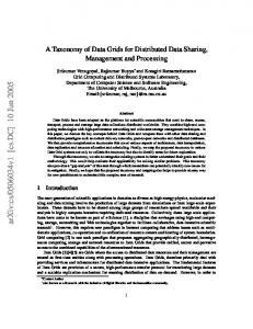
4. End-of-File Communication in Stream Mode: As pointed out by GGF GridFTP Working Group [15], during data upload, the server needs to treat the end of data socket as end of file. However, this method makes it impossible for the server to distinguish between normal end of file and abnormal client shutdown in the middle of data transfer [15]. After introducing some features that GridFTP has, the architecture of GridFTP will be focused. According to Allcock et. al [57], the GridFTP system developed by Globus is for (1) modularity which is to facilitate the substitution of alternative mechanisms and use in different environments and configurations, and (2) efficiency that can mainly avoid data copies [57]. The architecture listed below allows a protocol to be constructed by several independent modules that have different functions. As illustrated in the figure, there are some distinct components: client and server protocol interpreters (PIs), which handle the control channel protocol. The data transfer process (DTP), which handles the accessing of data and its movement via the data channel protocol.
Figure 1: GridFTP Architecture As shown in the figure [57], the DTP can be divided into a three-module pipeline - (1) The data access module that provides an interface to data source(s) or sink(s), (2) The data processing module that performs server-side data processing, and (3) The data channel protocol module which reads from or writes to the data channel. According to Allcock et. al [57], this basic structure provides a wide variety of systems, from simple file server logic (data access module reads or writes files, data processing module does nothing, data channel protocol module writers or reads the data channel) to more complex and specialized behaviors (for example, data module generates data dynamically in order to answer user requests).
Figure 2: GridFTP data transfer pipeline
CoreGRID TR-0121
5
For the protocol interpreter, the server PI handles the control channel exchange. In order to make it easy that a client contact a GridFTP server, the server PI must run as a daemon and listen on a well known port, otherwise other service must listen on the port and be configured to invoke the server PI [57]. The client PI then carries out its protocol exchange with the server PI. For DTP data access module, it is responsible for reading from or writing to a data source or sink. Its public interface includes transfer operations (list, send, receive) and command operations [57]. For DTP data processing module, it allows server-side data processing, such as compression, scaling, or concatenation of multiple files [57]. For DTP data channel protocol module, it handles data channel processing, such as the operations are required to receive or send data from or to the data channel. A single server may support multiple data channel protocols, where the MODE command is used to select the protocol to be used for a particular transfer [57]. The table listed below is to emphasize the advantages and disadvantages of GridFTP [14]. Advantages -Security -Parallel Streams -Striping -Partial File Transfer -Reliable and Restartable data transfer
Disadvantages -client should remain active all the times until the transfer finishes -transfer has to restart when client loss its state -features are tied to its protocol and implementation -memory leaks, unclear error responses and bugs may cause issues -difficult for users to decide a optimal number of streams
-Data Extensibility -Protocol Extensibility Table 1: Advantages and Disadvantages of GridFTP In order to make GridFTP achieve protocol features described above, the implementation of the GridFTP protocol consists of two APIs and corresponding libraries: globus-ftp-control and globus-ftp-client [12]. In addition, according to the Globus Team, APIs which are provided for GridFTP protocol also include interfaces for adding software “plugins” that makes adding “customized reliability and fault tolerance”, “performance monitoring”, and “extended data processing” easier for users [12]. bbFTP bbFTP is a file transfer system that uses multiple TCP streams between the same endpoints to speed up data transfers when the maximum TCP window size is lower than the BDP of the network path that is used for data transfer [9]. In addition, it is worth to point out users rather than bbFTP itself have the right to choose the number of streams [17]. Moreover, in order to further speed up data transfer, bbFTP uses several optimization techniques, such as on-the-fly data compression and automatic sizing of individual TCP windows [9]. Besides these features, bbFTP also provides a set of advanced functionalities concerning authentication [17]. The best example is that it provides SSH and certificate authentication modules. Meanwhile, it encrypts username and password but not the data which is being transferred at connection [17]. Because of these characteristics, some experts believe that it is a good choice for large data files transfer (larger than 2GB) [17]. The table below indicates the advantages and disadvantages of bbFTP.
CoreGRID TR-0121
6
Advantages -Parallel Streams -Encoded username and password at connection
Disadvantages -difficult for users to decide a optimal number of streams -can not perfectly reach fairness
-uses AFS authentication integration -uses On-the-fly data compression to improve performance Table 2: Advantages and Disadvantages of bbFTP
PSockets (Parallel Sockets) PSockets is a C++ library which applications can use to achieve almost optimal utilization of the network bandwidth without the necessity of tuning the TCP window size [26]. The basic idea behind PSockets is that it opens multiple socket connections between the sender and the receiver. Then it divides the data that needs to be transmitted into equal partitions, where the number of open sockets determines the number of partitions. After that PSockets sends the data partitions asynchronously over the multiple socket connections [26]. In this way, PSockets has the possibility to achieve the maximum data transfer rate on a high- speed wide area network without any network tuning. The approach mentioned here can be broadly viewed as analogous to striping data over arrays of disks [26]. The figure shown below is about TCP packets between a source and destination at a given time over a high speed wide area network. It includes three scenarios. In each case the same size data is to be transmitted from source to destination. In figure(a), the connection between the source and the destination has the default window size. At the source, the first TCP window size data is sent. The sender then waits for an acknowledgement before sending any more data. Because the source waits for an acknowledgement from the destination, the connection pipe between the source and destination is not completely filled. Therefore the maximum throughput over the connection is not achieved. In figure(b), this diagram illustrates the connection between the source and the destination after using RFC 1323 that enable the use of large TCP window sizes for connections when large BDP (bandwidth delay products) is existed. Here, the TCP window size is set to BDP size. In this scenario, the source sends the entire data that needs to be transmitted to the destination without waiting for an acknowledgement. It seems to achieve the maximum data rate between the source and the destination. The entire pipe is filled with segments. The reason i use “seem” here is because Enabling RFC 1323 on a system is determined by the system administrators at both ends rather than the application [26]. As indicated by Sivakumar, Bailey and Grossman [26], it could take a few days or several weeks to achieve that, therefore, “in practice most applications are limited to the default maximum window size”. Moreover, when the TCP window size is set to the BDP for the high-speed wide area network, the retransmission of the loss data can be costly and will affect the performance of the transmission [26]. In figure(c), it shows the method using multiple sockets(Using PSocket). No network tuning is required, and the TCP window size is set to the default value. Here, three sockets are used to fill up the pipe.
CoreGRID TR-0121
7
Figure 3: TCP Packets Sending over the network with and without PSocket As it is mentioned, by using PSockets library, there is no need for applications to tune for the best TCP window size in order to achieve the maximum throughput, since the throughput attained by PSockets is equivalent to the one that is obtained over a finely tuned network [26]. Whereas, for the reason of reducing the number of packets which need to be retransmitted, it is better for users to employ a smaller TCP window size [26].The table listed below focuses the advantages and disadvantages of PSockets. Advantages -Parallel Streams -Networking Striping -PSockets library is easily to be installed
Disadvantages -difficult for users to decide a optimal number of streams -it is doubtful PSockets can coexit with protocols without many sockets -the scalability is doubtful when more sockets are in use in long distance
Table 3: Advantages and Disadvantages of PSockets According to the TCP-based solutions (GridFTP, PSockets, bbFTP), it can be easily found that all of these approaches utilize parallel streams to overcome TCP’s drawbacks over high BDP. However, just as every medal has two sides, all this kind of protocols has several major problems. By using parallel TCP (GridFTP, PSockets and bbFTP), the bandwidth of networks can be utilized more efficiently, but this is not guaranteed. Performance of Parallel TCP relies on many factors, for example, the number of parallel flows, the buffer sizes of each flow, and etc. All of them have significant impact on the performance [21]. In addition, none of these protocols can perfectly reach fairness because parallel TCP inherits the RTT fairness problem of TCP [21]. Moreover, it is difficult for users to decide the buffer size and the number of streams in parallel TCP. Also, there are still several questions that need to be focused on, for instance, there seems to be no idea about whether all network nodes allow them, and whether or not the parallel streams still use the policy “one IP (port) source, one IP (port) destination and one queue”, which are practically destroying the parallelism. Because of shortcomings and questions listed above, therefore, experts propose UDP-based solutions as another scheme for high performance data transfer. 2.2.2 UDP-Based Solutions As indicated before, UDP-based solutions are provided by experts to be as another scheme for high performance data transfer. In the following part, several UDP-based solutions are introduced. UDP-based solutions, such as UDT, RBUDP, FOBS, SABUL, Tsunami and etc, use UDP to transfer data. They employ rate-based control algorithms to CoreGRID TR-0121
8
match the transmission speed [9]. At the same time, congestion and flow control algorithms may be used by some of the UDP-based solutions in order to keep the loss rate at a low level during transmission [9]. SABUL (Simple Available Bandwidth Utilization Library) SABUL (Simple Available Bandwidth Utilization Library) is an application-level data transfer protocol used for data-intensive applications over high BDP networks. According to Gu and Grossman [8], reliability, efficiency, high performance, fairness and friendliness are characteristics of SABUL. 1. Reliability: Although using unreliable UDP-based data channel to transfer data, SABUL also have the ability to detect and retransmit dropped packet by itself [8]. Meanwhile, in order to reduce the complexity of the reliability mechanism, SABUL uses TCP-based control channel to return control messages [18]. Therefore, it is easy for SABUL to achieve reliability. 2. Efficiency: In order to use available bandwidth efficiently or fully utilize the available bandwidth, SABUL is designed to have the ability to evaluate bandwidth and also to recover bandwidth from congestion events as soon as possible [8]. In SABUL, AIMD (additive increase multiplicative decrease) control algorithm is performed to tune the inter-packet transmission time [8]. In addition, packets are acknowledged at constant time intervals instead of being acknowledged every time when packet is received [8]. As a result, efficiency can be achieved by SABUL. 3. Fairness: SABUL is designed to be fair to other concurrent SABUL flows so that “grid applications can employ parallelism” [8]. In order to achieve fairness, all SABUL flows should ultimately reach the same rate with different network delays. Fortunately, by using rate-based congestion control algorithm to adjust the sending rate at uniform intervals rather than intervals determined by round trip time (RRT), SABUL can control flows rate [8]. In other words, fairness can be obtained by SABUL. 4. Friendliness: SABUL is proposed to be friendly to concurrent TCP flows [8]. In consequence, it is easier for people to deploy it in public networks [18]. In addition to these characteristics, SABUL also supports file transfer directly which often happens in high performance applications [18]. Moreover, it is not only for bulk data transfer, since there is no block size limit in SABUL [18]. That means it can be used in any kinds of data transfer. Finally, as presented by Gu and Grossman [8], “SABUL is designed as an application layer library so that it can be easily deployed without requiring any significant changes to an operating system’s network stacks or to the network infrastructure.” According to the advantages, such as it can efficiently use available bandwidth even on links with high BDP, it is fair to other SABUL flows, and it can coexist with TCP in both low BDP environments and high speed wide area networks, it can be easily demonstrated that SABUL is suitable for data-intensive grid applications over high performance networks. However, there are also several issues in SABUL need to be improved. The first one is a possibility of unfairness seems to be alive between concurrent SABUL flows. Secondly, the way for SABUL to set the rate control parameters is not very efficient at moment. Furthermore, a dynamic flow control algorithm needs to be designed instead of the fixed one that is in use currently [8]. Since SABUL is the original model for UDT (UDPbased data transfer protocol), the advantages and disadvantages of SABUL will not be listed here (please check the advantages and disadvantages of its successor – UDT) UDT (UDP-Based Data Transfer Protocol) UDT is an application-level data transport protocol for distributed data intensive applications over wide area high-speed networks [19]. It is not only for QoS-enabled networks, but for shared networks as well [19]. As indicated by Anglano and Canonico [9], UDT which uses UDP to transfer bulk data combines rate-based, window-based and delay-based congestion control mechanisms to achieve high throughput transmission with low data loss. UDT is developed from SABUL. The main reason for redesigning SABUL is the use of TCP, which is for control messages feedback in SABUL. According to Gu and Grossman [20], even though TCP can be easily implemented, the reliability and congestion control mechanism of TCP may cause control information delay in other protocols which
CoreGRID TR-0121
9
have already had their own reliability and congestion control. Since UDT is the descendant of SABUL, it inherits its predecessor’s advantages without any doubt. UDT employs window-based, rate-based and delay-based congestion control to achieve efficiency, fairness, friendliness and stability. By using window-based flow control, UDP can limit the number of unacknowledged packets to be sent out before the sending side receives any control information indicating congestion [20]. That means flow control window can be used for avoiding packet loss. As it is widely known, “low loss rate can reduce the frequency of sending rate decrease” [27]. Therefore, both the efficiency and the stability of UDT are improved. By using rate-based congestion control, the throughput of UDT flows can be influenced [9]. Due to the fact mentioned above, fairness depends on throughput in networks – different connections sharing the same network should have same throughput, the controllable throughput of UDT flows makes the protocol reach fairness. By employing a constant synchronization time instead of an interval determined by RTT, UDT have the ability to adjust sending rate. Consequently, the fairness bias by network delay can be eliminated [20]. However, there are some people who think fairness seems to contradict to TCP friendliness, since TCP is not RTT independent (it changes window size every RTT) and it is inefficient in high BDP environments. Although the point is correct, the issue still can be addressed – In low BDP networks where TCP can work well, UDT will obtain similar bandwidth as a TCP stream does, whereas, in high BDP networks, UDT can utilize the bandwidth that TCP fails to obtain [21]. The reason for this is that TCP has advantages over UDT in low RTT link, however, in high RTT link, UDT is better [20]. That is to say, the ratio between TCP and UDT bandwidth sharing increases with the decrease of RTT or the increase of bandwidth [20]. Therefore, coexistence can be provided between fairness and TCP friendliness. Besides these characteristics, UDT also has other advantages, such as the protocol is released as free software, it does not require any changes to existing network infrastructures or operating systems, it can be deployed directly as an application library, and “the original UDT library can be extended to composable UDT which can support various congestion control algorithms.” [21] In addition, there is one more attractive feature that should be noticed – UDT can be implemented above other packet-switched network layer, for example, it can become a transport layer protocol by using IP directly [20]. The figure listed below illustrates UDT in the layer architecture. In the figure, it can be easily found that UDT adapts itself into the network protocol architecture. In addition, the application exchanges its data through UDT socket, then UDT uses UDP to send or receive the data through the socket interface provided by operating systems. Meanwhile, memory copy is bypassed between UDT socket and OS socket interface.
Figure 4: UDT in the Layer Architecture
CoreGRID TR-0121
10
In the following several paragraphs, the UDT protocols is going to be described detailed. UDT is an end-to-end transport protocol, each entity in UDT has two parts: a sender and a receiver. The sender in UDT entity is mainly used for data packet sending, while the receiver is for data packet receiving, control packet (including congestion control and reliability control) triggering and processing, and also timer expiration detection [20]. What we should note is that “all data and control packets in both directions are transferred between a pair of UDP ports.” [20] In the figure below, a UDT entity A sends data packets to another UDT entity B. As illustrated in the figure, the data is sent from A’s sender to B’s receiver, however, the control packet is exchanged between A’s receiver and B’s receiver [20].
Figure 5: UDT Entity in the Protocol As can be seen in the following figure, there are two types of packets in UDT: data packet and control packet [21]. They are distinguished by the first bit of the packet header (that will be introduced in the following paragraph). In UDT data packet, as shown in the following figure [21], the packet header includes a Sequence Number field, a Message Sequence Number field, and a Time Stamp field. The UDT’s sequencing is similar with TCP’s sequencing, but the most difference between them is that UDT provides packet-based sequencing comparing with byte-based sequencing provided by TCP. The message number field in the packet header indicates which packets consist of a particular application message. A message may contain one or more packets. The “FF” filed provides the message boundary: from the first packet (10) to the last packet (01), and also the solo packet (11). The “O” field reveals whether the message is transferred in order, which means all messages prior to the message are either delivered or dropped before its delivery.
Figure 6: Data Packet In UDT control packet, as shown in the following figure [21], the packet header contains a Type field, an Extended Type field, an ACK Sub-Sequence Number field, a Time Stamp field, and a Control Information field. Actually, there are seven types of control packets whose type information is specified in the bit field 1 - 15 of the packet header [20]. They are: handshake that is for connection setup (type 000), keep-alive (type 001), ack that is acknowledgment (type 010), nak that is for negative acknowledgment or loss report, the total number of lost packets are counted and carried in the filed (type 011), ack2 that is acknowledgment to acknowledgment (type 110), shutdown, and message drop request. The extended type field is reserved for users to define their own control packets in the composable UDT framework. In addition, UDT uses sub-sequencing for ACK packets which also carries RTT, packet arrival speed, and estimated bandwidth [21]. Each ACK packet is assigned a unique sequence number, which is independent from the data packet sequence number. What should we notice is that the first three 32-bit fields must be included in the control packet header. However for control information field, it can contain no any information, which depends on the packet CoreGRID TR-0121
11
type [21].
Figure 7: Control Packet As I mentioned before, data packet and control packet are distinguished by the first bit (flag bit) of the packet header [21]. The header of a data packet is a flag bit of “0”. Whereas, the first bit of a control packet header is defined as “1”. As discussed by Gu and Grossman [21], UDT supports two kinds of connection setup – traditional client/server mode, and rendezvous mode. In the traditional client/server mode, one UDT entity starts first which will be defined as the server, and its peer side (the client) that hopes to connect to it will send a handshake packet, containing 1) UDT version, 2) socket type, 3) initial random sequence number, 4) maximum packet size, and 5) maximum flow window size, to it [21]. The client keeps on sending the handshake packet every constant interval, which is decided by the balance between response time and system overhead, until it receives a response handshake from the server or a time-out timer expires. When a server receives a handshake packet, if the request has the same version and type, it compares the packet size with its own value and sets its own value as the smaller one [21]. Then the result is sent back to the client with a server’s initial sequence number and maximum flow window size. That means the server gets ready for sending/receiving data. In addition, the server must send back a response packet as long as it receives any further handshakes even from the same client. The reason for this situation is for preventing the client not receiving the previous response. After getting the response from the server, the client can start sending/receiving data. Also, further handshake responses from the server will be ignored. Due to the fact that a traditional client/server setup process needs a server to be started first and a client sends requests to it, which is very difficult if both of servers and clients are behind firewalls. The other connection setup – rendezvous connection setup mode is proposed [21]. In this setup model, each UDT socket sends a connection request to its peer side, and once the peer side receives the request, it sends back a response and set up the connection. If one of the connected UDT entities is being closed, it sends a shutdown message, which is only sent once, to the peer side. Once receiving this message, the peer will also be closed. If the message is not received, the peer will be closed by a timeout mechanism through the keep-alive packets [21]. Here, I should mention that a UDT entity can detect a broken connection if it does not receive any packets in a certain predetermined time. After introducing two kinds of connection setup, the UDT’s sending and receiving algorithms will be introduced. According to Gu and Grossman [20], the sender keeps sending out one packet every inter-packet time which is decided by the rate control mechanism. In addition, retransmitted packet has higher priority than first time packet. Moreover, once a packet is resent, it will be removed from the sender’s loss list that is held by sender and receiver respectively for recording lost packets sequence numbers. Finally, the sender will not send out any new data packet if the number of unacknowledged packets exceeds a threshold, or the flow window size, which is updated by the flow control mechanism. A UDT sender’s algorithm [20] will be specified at the addendum section of the report. When a receiver receives data or control packets, it processes packets according to the packet type. For a data packet, the receiver checks the sequence number and writes the data into the proper position of the protocol buffer [20]. If the packet has already been acknowledged, it will be discarded. All the sequence numbers between the current sequence number and the received largest sequence number plus one, will be added into the receiver’s loss list. An NAK report is generated and sent back immediately. If the sequence number is listed in the loss list, which means its number is less than the largest received, it will be removed from the list. For a control packet, the explanation will be given CoreGRID TR-0121
12
later. A UDT receiver’s algorithm [20] will also be indicated in the addendum section of the report. In UDT protocol, acknowledgment is used for congestion control and data reliability. As mentioned above, in high speed networks, generating acknowledgments for every received packet can waste an amount of time. Also, the acknowledgment utilizes some bandwidth. Therefore, as introduced above, UDT protocol uses timer-based selective acknowledgment, which generates an acknowledgment at a fixed interval [21]. In that case, the faster the transfer speed, the smaller the ratio of bandwidth utilized by control flow. UDT uses ACK sub-sequencing to avoid sending repeated ACKs that is assigned a unique ACK ID [20]. An ACK2 packet with the same ACK ID is generated each time once an ACK is received. When the receiver side receives the ACK2, it means the ACK has reached its destination. Then, the receiver checks the ACK history window in order to have an acknowledgment update. Furthermore, the UDT receiver can also use the departure time of the ACK and the arrival time of the ACK2 to calculate RTT [21]. In addition, as pointed out by Gu and Grossman [20], it is not necessary to generate an ACK2 for every ACK packet, and light ACKs can be generated to help synchronize the packet sending. NAK is used only if there is loss to report so that the sender can resent as quickly as possible. Comparing with TCP SACK field, the mechanism - NAK packet that UDT provides can bring more information. The figure illustrated below shows the architecture of the UDT (the solid line represents the data flow, the dashed line represents the control flow) [21].
Figure 8: the Architecture of the UDT As discussed above, UDT has a lot of advantages which make it become a right choice for high performance data transfer. However, it still has its own bottlenecks. The major limitation of UDT is the calculation of increase parameter that makes UDT less attractive for links with very large amounts of concurrent flow [20]. Since UDT is a successor to SABUL, it has many advantages that SABUL original has. The table listed below highlights the advantages and disadvantages of UDT [21].
CoreGRID TR-0121
13
Advantages -TCP friendliness
Disadvantages -High computational overhead
-RTT fairness
-High complexity of rate-control and flowcontrol algorithm -not suitable for links with very large amounts of concurrent flow
-Support both stream and datagram transfer modes -allows emulating behavior of other protocols -Optimized for high-bandwidth moderatelatency environment
Table 4: Advantages and Disadvantages of UDT
RBUDP (Reliable Blast UDP) RBUDP (Reliable Blast UDP) is a protocol only used for dedicated or QoS-enabled high bandwidth networks [22]. In order to fully utilize network bandwidth during bulk data transfer, it not only discards TCP’s slow start and congestion control mechanism, but aggregates acknowledgements as well. As pointed out by He, Leigh and Yu [22], in RBUDP, acknowledgments are aggregated and sent at the end of every transmission phase instead of per window of transmitted data. In the transmission phase, by using UDP datagrams the source machine sends the whole data to the receiver at a user-specified sending rate. After collecting a signal - DONE, which means no more UDP packets will arrive, from source machine, the receiver sends back a list of all missing packets via a TCP connection. Then, the data sender retransmits these lost packets. This process is repeated until no more packets need to be retransmitted [9]. What should we notice is that because UDP is an unreliable protocol (some datagrams may be lost during the transmission), the receiver should have a tally of the packets that are received in order to make sure which packets need to be retransmitted.
Figure 9: RBUDP Data Transfer
CoreGRID TR-0121
14
As can be seen from the above paragraph, in RBUDP, data packet and control packet are exchanged via UDP and TCP respectively. In addition, the sending rate is assigned manually. In order to minimize packet loss, the rate should not be larger than the minimum bandwidth of the link [22]. However, what should we notice is that, in practice, it is difficult for users to measure the minimum bandwidth of the link [22]. In RBUDP, packet loss rate is not only based on the sending rate, but also determined by receiver’s CPU. As presented by He, Leigh and Yu [22], if a faster computer is selected as a receiver which can keep up with the network while moving data from the kernel buffer to application buffers, the loss rate will be lower than selecting a slower computer as a receiver. In addition, there is another obvious drawback in RBUDP – the protocol is only suitable for large data transmission rather than smaller ones. The table figured below gives the advantages and disadvantages of RBUDP [22]. Advantages -Keep bandwidth as full as possible -Avoid TCP’s per-packet ack interaction -performance is predictable
Disadvantages -difficult to assign sending rate manually -no flow control in RBUDP -packet loss rate is determined by receiver’s CPU -is only suitable for large data transmission
Table 5: Advantages and Disadvantages of RBUDP
FOBS FOBS is a user-level, UDP-based data transfer mechanism which is designed for large-scale data transfers in the high-bandwidth and high-delay network environment [28]. Unlike RBUDP, there is some degree of interaction between the sender and the receiver [9]. More specifically, the sender transmits a batch of fixed size data packets which includes both unsent and retransmitted packets. Then the receiver sends back acknowledgement which contains a list of unreceived packets to sender. According to the acknowledgement, the sender decides the number of lost packets which need to be resent in the next batch. Like RBUDP, the process is repeated until all data packets arrive to the receiver [1]. The Data sending and receiving Algorithm [28] will be listed in the addendum section of the report Although some experimental results show that FOBS can perform well in a computational grid environment, it still has its issues [28]. FOBS is a very aggressive transport mechanism that does not adapt to changes in the state of the end-to-end system. Therefore, in order to make FOBS useful in a general grid environment, a congestion control mechanism should be developed. The table below provides the advantages and disadvantages of FOBS Advantages -additional load placed on the network is reasonable (3 percent of the total data transferred) -can achieve higher available bandwidth on long-haul connections over the network than PSockets does -only has very minimal packet loss across all connections tested
Disadvantages -is a lightweight protocol, only operating outside of the large systems. -can’t obtain a very large percentage of a gigabit connection implementation is inefficient -does not provide congestion control
Table 6: Advantages and Disadvantages of FOBS
Tsunami Tsunami is designed for high-speed file transfer over uncongested networks [23]. It shares many features in common with other UDP-based solutions, such as these protocols use UDP as transport mechanism to facilitate file transfer and TCP stream as control mechanism to authenticate and negotiate the connection [24], and they use inter-packet delay instead of the sliding window algorithm to manage the basic transmission rate [23].
CoreGRID TR-0121
15
According to Ansari [24], the Tsunami architecture follows a typical client/server model. In order to attempt file transfer, the client initiates a Tsunami session by asking the server for a specific file on the TCP control port. The server creates a thread in response to the request and goes back waiting for the next connection. The created thread checks for the file and transmits the file to the client on a known UDP port. Ansari [24] also indicated that, in the Tsunami protocol, files are transferred block by block whose size is variable. Furthermore, since the Tsunami protocol uses UDP which can not guarantee reliable delivery to transfer files, like other UDP-based solutions, it has to have its own reordering and retransmission mechanism [24]. That is to say, when any dropped, delayed or out of order blocks are detected by the client, it sends a retransmission request for that block to the server on the TCP control connection. In addition, retransmission request should be sent by client to the server due to the fact that the server in Tsunami does not keep any state for the file transfer [24]. Although the Tsunami protocol is especially designed for high-speed file transfer and it seems to be a promising tool, it still has several drawbacks need to be overcome. The first shortcoming is that networks for using Tsunami are typically not congested [25]. The most reason for this is that the client can have enough capability to handle the incoming traffic without any form of flow control [25]. Secondly, there is little literature or experiment result shows whether or not Tsunami transfers can interact with other flows on the same path through the network. Finally, it is impossible for researchers to exhaustively search the Tsunami parameter space for optimal settings, since the parameter space has many dimensions [25]. The table figured below points out the advantages and disadvantages of Tsunami protocol. Advantages -able to allow users to tune the protocol -relatively insensitive to network latency
Disadvantages -Tsunami is not suitable for congested networks -not sure whether its transfers can interact with other flows -impossible for users to have a optimal settings in Tsunami -It is not TCP Friendly -performance is not predictable
Table 7: Advantages and Disadvantages of Tsunami From the above review of UDP-based solutions, it can be easily found that although rate-based protocols, such as RBUDP, FOBS and Tsunami, are regarded as a solution to overcome TCP’s inefficiency, none of them are really suitable for high performance data transfer. The biggest reason for this is that all of these protocols are designed for private or QoS-enabled networks and the congestion control algorithms they have are only for the purpose of high utilization of bandwidth [27]. Then, SABUL and its superset-UDT came up. Although, UDT has its bottlenecks, it is still charming to experts for its efficiency, fairness, friendliness, stability and high scalability, which are very important for many distributed applications.
2.3 Contrast between Two Different Application-Level Solutions There is a result between TCP-based solutions and UDP-based solutions presented by Anglano and Canonico [9] “for relatively low BDP networks both TCP-based and UDP-based solutions achieve similar performance, for higher BDP networks UDP-based tools are definitely the only viable option.” However, Anglano and Canonico [9] also indicate simply using UDP does not automatically result in good performance, such as mechanisms without any rate-based congestion control is not able to achieve good performance comparable with those which have rate-based congestion control.
CoreGRID TR-0121
16
3 Mechanisms for High Volume Data Transmission in Enterprise Data Centers As noted in the introduction of the report, most application-level solutions are typically used in “traditional” Grids, where data storage is directly attached with Grid nodes. However, as Computational Grid is moving towards Enterprise Data Centers, it will face difference resource and service management challenges. In order to overcome these issues, many other types of data transmission mechanisms in instead of application-level solutions are utilized to access data by Enterprise Data Storage solutions, such as NAS and SAN. In this section, it gives general idea for these data transmission mechanisms used by Enterprise Data Storage solutions. Also, it focuses on features of SAN and NAS these two storage solutions. Therefore, the section is divided into four parts. The first part gives the brief description of SAN and NAS these two storage solutions. The following part emphasizes some core concepts of SANbased storages. Meanwhile, data transmission mechanisms used in SAN-based storages are discussed. After that, the detailed description of NAS-based storage is provided. At the same time, solutions for data transmission in NAS-based storage are considered. Finally, the contrast between these two kinds of Enterprise Data Storage solutions is given.
3.1 The Brief Description for SAN and NAS SAN (storage are network) and NAS (Network attached Storage) are two storage solutions to provide access to different types of data. According to Meyer [34], SAN is widely for high-volume block-oriented data transfer, while NAS is usually for data access at the file level. In other words, SAN supports a range of applications, including providing storages for NAS appliances. NAS storage is typically limited to applications that access data at the file level [31]. Regardless of their differences, both these two technologies satisfy the need to remove direct storage-to-server connections to facilitate more flexible storage access. In addition, both SAN and NAS are based on open industry-standard network protocols-Fiber Channel for SAN, and networking protocols such as TCP/IP for NAS [33]. SAN and NAS play important roles in today’s enterprises and provide many advantages over traditional server-attached storage implementations. With SAN and NAS increasingly replacing or supplementing traditional server-attached storage implementations in many data centers, a wide range of benefits, including increased flexibility, easier storage deployment, and reduced overall storage costs are presented [34]. Although both SAN and NAS technologies can provide a competitive advantage, each is designed for specific types of environments and applications.
3.2 SAN-Based Storage In this part, some core concepts of SAN-based storage, such as the characteristics, the main advantages and disadvantages, the applications of SAN are provided. Moreover, data transmission mechanisms used in SAN-based storages are presented in the part. 3.2.1 SAN Characteristics SAN (storage area network) is an architecture to attach remote computer storage devices (such as disk arrays, tape libraries and etc.) to servers [29]. The devices mentioned here appear as locally attached to the operating system in SAN. For some enterprises, by enabling many direct connections between servers and storage devices, SAN is able to provide a flexible, high-performance, and highly scalable storage environment [29]. High-performance Fiber Channel switches and Fiber Channel network protocols ensure that device connections are both reliable and efficient [29]. Because SAN is optimized to transfer large blocks of data between servers and storage devices, they are ideal for a wide variety of applications, such as [34]: • Mission-critical database applications where predictable response time, availability, and storage scalability are essential • Centralized storage backups where performance, data integrity, and reliability ensure that critical enterprise data is secure • High-availability and application failover environments that ensure very high levels of application availability at reduced costs CoreGRID TR-0121
17
• Scalable storage virtualization, which detaches storage from direct host attachments and enables dynamic storage allocation from a centralized pool • Improved disaster tolerance, which provides high Fibre Channel performance at extended distances (up to 150 km) between host servers and connected devices 3.2.2 Main SAN Strengths Because SAN offers excellent scalability, they are becoming the infrastructure of choice for large enterprises and service providers that face rapidly expanding data storage requirements [29]. In fact, SAN provides many significant advantages over traditional storage architectures. For instance, traditional server-attached storage is often difficult to update or centrally manage. Each server must be shut down to physically add and configure new storage. In contrast, SAN provides a way to add storage without the downtime and disruption associated with server-attached storage upgrades [34]. SAN also helps centralize data management, which greatly reduces overall operating costs [29]. With the help of Fiber Channel technology, SAN optimizes the efficient transfer of block data. By supporting applications that involve high-volume block transfers between storage and servers, SAN provides a way to streamline data backups [29]. As a result, valuable network bandwidth traditionally used for data backup can be used instead for more strategic applications. Open, industry-standard Fiber Channel technology also makes SAN extremely flexible [30]. By overcoming the cabling restrictions traditionally associated with SCSI, SAN increases the distance between servers and storage while enabling many more connection possibilities [34]. Improved scalability also simplifies server deployments. Moreover, SAN enables a higher degree of control over the storage network environment-meeting the performance and availability requirements of transaction-based systems [30]. Another key advantage of SAN is the ability to deliver block data to enterprise-level data-intensive applications [29]. During data transfer, SAN imposes less processing overhead on communicating nodes (particularly servers), since data is broken into fewer segments during transmission [29]. As a result, Fiber Channel SAN is much more effective at delivering large bursts of block data-which makes Fiber Channel an ideal protocol for storageintensive environments. Today, SAN is increasingly implemented in conjunction with NAS environments to provide high-performance, large-capacity storage pools for NAS facilities. In fact, many SAN currently are utilized behind NAS appliances to address storage scalability and backup requirements [34]. 3.2.3 SAN Drawback Although as I mentioned in the last section, storage devices in SAN appear as locally attached to the operating system. The Operating system still recognizes SAN as a collection of LUNs (Logical Unit Numbers) and is supposed to maintain its own file system on them [35]. As it is widely known, the most reliable and most widely used are the local file system, which can not be shared among multiple hosts. Therefore, sharing data between computers through a SAN requires advanced solutions, such as SAN file systems or clustered computing [35]. In addition, SAN also has problems in compatibility. Switches and hardware in SAN from different manufacturers are not entirely compatible [35]. Although the basic storage protocols FCP is nearly standard, some of the higherlevel functions did not interoperate well [29]. In addition, many host operating systems do not react perfectly to other operating systems by sharing the same fabric [29]. 3.2.4 SAN Applications and Benefits One of the key benefits realized in SAN environments is the improved reliability and scalability of enterprise data backup and restore operations [29]. SAN-based operations can reduce backup and restore times by decreasing the amount of traffic running on the corporate network.
CoreGRID TR-0121
18
By extending the SAN across Metropolitan Area Network (MAN) infrastructures, SAN also improves disaster tolerance through the seamless connection of remote facilities [29]. SAN employs MAN infrastructures to increase the distance between SAN components. However with the increasing in distance, there is little or no decrease in performance [29]. “Organizations can use the capability to improve disaster tolerance by deploying failover facilities for mission-critical applications and remote data replication for critical application servers [29]” In addition, SAN backup and restore facilities are also an ideal candidate for remote implementations. SAN also provides a cheaper way to address high-availability application requirements. Traditional high-availability configurations require a hot standby server for each main server in a high-availability server pair [30]. By removing direct storage-to-server attachment and deploying a SAN, it is possible to enable a single standby server to support multiple main servers. Moreover, it decreases the amount of extra storage required for each server [30]. In addition, improved server availability and more effective storage capacity utilization reduce the total cost of ownership for the server complex. 3.2.5 Network protocols used by SAN Devices As indicated by EMULEX and BROCADE, SCSI (Small Computer System Interface) protocol is widely used in storage networks for communication between servers and disk drive devices [35]. However, due to the fact that SCSI bus topology is not suitable for networking, other alternative protocols are introduced, such as FCP, iSCSI, AoE, FCoE and etc [35]. Fiber Channel Protocol (FCP) Fiber Channel Protocol is the interface protocol of SCSI on the Fiber Channel. According to Meggyesi, Fiber Channel is a gigabit-speed network technology mainly used for storage networking, especially for storage area networks (SAN) in enterprise storage [36]. It can be utilized to support other “upper layer” protocols, including SCSI, ATM and IP. It is a layered protocol which consists of 5 layers [37]: • FC0: The physical layer, which contains cables, fiber optics and etc. • FC1: The data link layer, which implements the 8b/10b encoding and decoding of signals. • FC2: The network layer, which consists of the core Fiber Channel. • FC3: The services layer, which can implement functions like encryption or RAID. • FC4: The protocol mapping layer, where other protocols, such as SCSI, are encapsulated into an information unit. For these layers mentioned above, FC0, FC1 and FC2 are the physical layers of fiber channel [37]. In addition, as noticed by Meggyesi [36], Fiber Channel products are available at 1 Gbit/s, 2 Gbit/s, 4 Gbit/s, 8 Gbit/s and 10 Gbit/s. Products based on the 1, 2, 4 and 8 Gbit/s standards can be interoperable and compatible. However, the 10 Gbit/s standard is not compatible with any other slower speed devices, since 64b/66b encoding instead of 8b/10b encoding is used on FC1 level. There are three major topologies in Fiber Channel (FC-P2P, FC-AL, and FC-SW), which notifies how ports are connected together [36]. • Point-to-Point topology (FC-P2P): in Point-to-Point topology, two ports are connected back to back. • Arbitrated Loop topology (FC-AL): in Arbitrated Loop topology, all ports are in a loop or ring. The behavior such as adding or removing a port from the loop or ring causes all activity on the loop to be interrupted. Moreover, the failure of one port causes a break in the ring. • Switched Fabric topology (FC-SW): All ports or loops of ports are connected to Fiber Channel switches. The switches manage the state of the fabric, providing optimized interconnections. In general, Fiber Channel Protocol is the most common SAN protocol. CoreGRID TR-0121
19
Internet SCSI (iSCSI) iSCSI is a network protocol standard, which allows mapping SCSI protocol over TCP/IP networks. As indicated by Orenstein [38], iSCSI is a transport layer protocol in the SCSI-3 specifications framework. Unlike other network storage protocols, such as Fiber Channel, it only requires Ethernet interface (or any other TCP/IP-capable network) to operate, which decreases the cost of storage centralization [39]. In other words, with the popularity of gigabit Ethernet, building iSCSI-based storage area networks (SAN) has become a less costly way to take the place of Fiber Channel-based SAN. Due to the fact that the overhead added by the TCP/IP protocol to the communication between client and storage is very heavy, some experts worried about the worse performance. However, with the introducing of new techniques such as TCP Offload Engine (ToE), which “is used in network interface cards to offload processing of the entire TCP/IP stack to the network controller” [40], iSCSI-based SANs have shown excellent performance. Moreover, as more and more organizations and manufacturers deploy Gigabit and 10 Gigabit networks, and integrate iSCSI support into their operating systems, SAN products and storage subsystems, the performance and usability of iSCSI should be improved [38]. In the iSCSI-based storage, the operating system that is in control of the iSCSI device allows a machine to use an iSCSI initiator to connect to remote targets such as disks and tape drives [39]. The point that should be mentioned is an iSCSI initiator, in client/server terminology, is similar to a client, while an iSCSI target here is similar to a server where it provides block level access to its storage media [41]. Additional, the main difference between a client/server system and an iSCSI initiator/target system is that many clients can simultaneously access the same files offered by a single server, while iSCSI initiators require complex coordination to synchronize accesses to the same files [39]. In other words, allowing multiple hosts to have simultaneous access to a single device is a difficult task for iSCSI and FC devices. The standard authentication scheme used in iSCSI is CHAP (Challenge-Handshake Authentication Protocol) which is used by Point-to-Point servers to validate the identity of remote clients [42]. However, since CHAP is known to be insecure, IPSec can also be used at the network layer. Moreover, another authentication method used in iSCSI is SRP (Secure Remote Password) which is a password-authenticated key agreement protocol [43]. Generally speaking, more and more people believe that iSCSI is becoming even more appealing because Ethernet can support higher speeds than Fiber Channel [38]. The following diagram shows a part of the iSCSI architecture model.
Figure 10: iSCSI Architecture Model
CoreGRID TR-0121
20
In the figure, there are some concept needs to be explained [39]. For more detailed defination, please see [39]. • Network Entity: “it represents a device or gateway that is accessible from the IP network. A Network Entity must have one or more Network Portals, each of which can be used by some iSCSI Nodes included in the Network Entity to access to the IP network.” • iSCSI Node: “it represents a single iSCSI initiator or iSCSI target. There are one or more iSCSI Nodes within a Network Entity. The iSCSI Node is reachable via one or more Network Portals. An iSCSI Node is identified by its iSCSI Name. Note: it allows multiple iSCSI nodes to use the same addresses, and the same iSCSI node to use multiple addresses.” • Network Portal: “It is a component of a Network Entity that has a TCP/IP network address and that may be used by an iSCSI Node within that Network Entity for the connection(s) within one of its iSCSI sessions. In an initiator, it is identified by its IP address. In a target, it is identified by its IP address and its listening TCP port.” • Portal Groups: “iSCSI supports multiple connections within the same session; some implementations will have the ability to combine connections in one session across multiple Network Portals. Not all Network Portals within a Portal Group need to participate in every session connected by the Portal Group. One or more Portal Groups may provide access to an iSCSI Node. Each Network Portal belongs to one portal group within the node. Portal Groups are identified within an iSCSI Node by a portal group tag, a simple unsigned-integer between 0 and 65535. All Network Portals with the same portal group tag in the context of a given iSCSI Node are in the same Portal Group.” AoE (ATA over Ethernet) ATA over Ethernet is a network protocol that is designed for accessing ATA storage devices over Ethernet networks [45]. It gives the possibility to build SANs with low-cost, standard technologies. In addition, the AoE does not rely on network layers above Ethernet, such as IP, UDP, TCP, and etc. This is to say AoE is not routable over LANs and is intended for SANs only [45]. Although AoE seems to be a simple network protocol, it proposes a new way for storage possibilities. The ATA here is a kind of wire protocol for disk drives [44]. The AoE protocol simply puts ATA commands into low-level network packets, so that an Ethernet network can effectively replace the cable that goes to the disk drive [44]. This means it is very easy for blocks of data to go to a disk drive over Ethernet cables. Furthermore, Ethernet cables do not care the inside of the blocks of data. According to Hopkins [45], since AoE uses Ethernet network to access block storage, it has several potential advantages, such as it is easier to add storage capacity, the amount of storage is practically unlimited, access can be controlled by creating ad hoc Ethernet networks, common hardware can be used, data backup can be easier, and data can be shared instead of being confined in one computer. Here, what should we notice is the last advantage. Traditionally, the file system which is for data management is used on a computer which is the only one user of its hard disk, NTFS, XFS, and ext3 are examples of that. However, due to the advantage listed above, it is possible for AoE to allow multiple members to use a shared block device safely, by coordinating their actions [46]. As indicated by Hopkins and Coile [46], the AoE protocol provides a mechanism for host-based cooperative locking. When more than one AoE initiator is using an AoE target, they will cooperate. They can simply communicate by using such as TCP/IP to send messages to one another. Through communication, the hosts can agree which one has the right to access particular blocks on the shared storage. The reason for negotiation among these hosts is they need a way to avoid interfering with others as they use and modify the data on the shared AoE device. Another option is to use the storage device itself to determine the access of particular hosts. If more than one host tries to set the “config string” to access the same data, only one can succeed. The rest hosts will receive an error. At that point, the “winner” is decided and the winner can proceed to establish an access policy [46]. As it is widely known, ATA over Ethernet (AoE) is an open standards-based protocol designed to efficiently transfer ATA disk commands over Ethernet. Besides the advantages noticed above, it still has some strength. Unlike iSCSI, AoE is a thin-layer protocol that is trafficked on the top Ethernet. (See Figure below) AoE encapsulates standard ATA disk commands directly into Ethernet frames, which leads low latency, low overhead connection between servers and CoreGRID TR-0121
21
block level storage over a standard Ethernet link [45].
Figure 11: Comparison between AoE and iSCSI Stack Moreover, since AoE has no need to process a TCP/IP stack, neither TCP offload engine (TOE) nor special Host Bus Adapter is required to achieve good performance [45]. Also, AoE is easily decoded and it’s not a routable protocol. In addition, because using modern Ethernet switches that support flow control, zero AoE packet retransmission is achieved, each packet sent in AoE has a positive acknowledgement [45]. Final, AoE protocol includes user customization features. Additionally it provides a way for target device discovery by knowing storage device physical location parameters [45]. All these features are especially important in large storage arrays consisting of thousands of storage devices. In the following several paragraphs, the AoE header format will be specified. In the header, the version field defines the AoE header format as well as a set of command codes. The Flags field contains three kinds of bit respectively [46], (1) R bit that is for the message is a response, (2) E bit is created in a response message when the associated command message generates an AoE protocol error, and (3) Z bits are reserved and must be set to zero. In the Error field, if Flags bit E is appeared, the field will include an error code [46] such as: (1) Unrecognized command code, (2) Bad argument parameter, (3) Device unavailable, (4) Config string present, and (5) Unsupported version. In Major and Minor field, each AoE server has a major and minor address. Before processing the header Command, the server must validate its major and minor addresses which are set in the header. Once both of the following case – the Major field in the header is the server major address or all ones (0xffff), and the Minor field in the header is the server minor address or all ones (0xff) are true, a server will accept a command message for processing [46]. What should be noticed is that a server must set its major and minor address in every response. In the Command field, it contains command codes for the message. There are two categories of command (figures listed below) [46]: (1) Command 0 that is used to issue an ATA command to an attached ATA device, and (2) Command 1 that obtains configuration information from the server and sets it in certain cases. For more detailed information about these two commands, please see [46]. In the Arg field, it “defines” serve as input for the specified command code.
CoreGRID TR-0121
22
Figure 12: AoE Header Format
Figure 13: ATA Command 0
Figure 14: ATA Command 1 From the description above, it can be found that ATA over Ethernet is an alternative way for communication between servers and disk drive devices. It can be easily used in storages on the local network. FCoE (Fiber Channel over Ethernet) Fiber Channel over Ethernet is proposed to map Fiber Channel over Ethernet. According to DeSanti and Gai, “This would allow Fiber Channel to leverage the technology of Ethernet while preserving the main parts of the Fiber Channel protocol.” [47] FCoE replaces the physical layer of the Fiber Channel stack by Ethernet that allows a seamless integration in existing Fiber Channel networks and management software [48]. In FCoE, the Host Bus Adapter (HBA) appears as a Fiber Channel Card to the server and as a Ethernet Card to the network. As a result it can provide IO consolidation over Ethernet when reducing network complexity in the Datacenter [48]. Since the project has been proposed in American National Standards Institute (ANSI) in April 2007, it will take some time before a new standard is approved. CoreGRID TR-0121
23
3.3 NAS-Based Storage In the following part, some core concepts of NAS-based storage, such as the characteristics, the main advantages and disadvantages, the applications of NAS are indicated. Furthermore, data transmission mechanisms used in NAS-based storages are focused on in the part 3.3.1 Key NAS Characteristics NAS (Network-attached storage) is a file-level data storage which is connected to a computer network providing data access to heterogeneous network clients [31]. As indicated by BROCADE [49], “NAS are typically configured as fileserving appliances accessed by workstations and servers through a network protocol such as TCP/IP and applications such as Network File System (NFS) or Common Internet File System (CIFS) for file access.” Most NAS connections are between clients and the NAS file-sharing facility. These connections rely on the underlying corporate network infrastructure [49]. NAS enables organizations to quickly and easily add file storage capacity to their technology infrastructure [31]. Because NAS focuses on serving files while hiding many of the details of the actual file system implementation, NAS devices are often self-contained and relatively easy to deploy [31]. Typical interaction between a NAS client and a device involves relatively short duration and volume data transfers [31]. That means, large packet transfers need to be split into many small pieces. Additional processing is required at each end of the connection to break down and reassemble the data stream. As it is widely known, when the number of packets involved in the transfer increases, applications running on the same server might be restricted if too many processor resources are used by packet processing. As a result, “a key NAS performance constraint is the ability of the network to deliver the data since network congestion directly affects NAS performance” [31]. According to Singer [32], “NAS storage scalability is often limited to the size of the appliance enclosure. Adding another appliance is relatively easy, however accessing the combined contents as a single entity is not easy, since appliances typically have unique network identifiers.” Because of these constraints, data backups in NAS environments are usually not centralized. As a result, NAS might be limited to direct-attached devices (such as dedicated tape drives or libraries) or a network-based strategy where the appliance data is backed up over a corporate or dedicated LAN [32]. 3.3.2 Main NAS Strengths NAS works well for organizations which need to deliver file data to multiple clients over a network. NAS appliances also have good function in environments where data must be transferred over very long distances. Because most NAS requests are for smaller amounts of data, distance and network delays are less critical for data transfer [49]. In addition, NAS appliances are easy to deploy-enabling widespread distribution of NAS hosts, clients, and appliances in the whole enterprise. With properly configuration, NAS provides reliable file-level data integrity, because file locking is handled by the appliance itself [31]. 3.3.3 NAS Drawbacks Although NAS has its advantages, it still has several disadvantages. If the NAS is occupied with many users, too many I/O operations, or CPU processing power, the NAS will reaches its limitations. As it is known, a sever system is easily upgraded by adding one or more servers into cluster, therefore, CPU power can be upgraded easily. While, the NAS is limited to its own hardware which is almost not upgradeable [49]. 3.3.4 NAS Applications and Benefits NAS applications tend to be most efficient for file-sharing tasks, such as NFS in UNIX and CIFS in Windows NT environments, where network-based locking at the file level provides a high level of concurrent access protection [32]. NAS facilities can also be optimized to deliver file information to many clients with file-level protection. There are two common applications that utilize the effectiveness of NAS – hosting home directories, and providing a data store
CoreGRID TR-0121
24
for static Web pages that are accessed by many different Web servers [32]. For those applications where the majority of data access is typically read-only, the databases are small, access volume is low, and “predictable performance is not mandatory”. NAS can be deployed to help reduce overall storage costs [49]. 3.3.5 Network protocols used by NAS Devices As mentioned in the report above, NAS uses file-based protocols such as NFS (popular on UNIX systems), SMB (Server Message Block) (for Windows systems) and etc [49]. Therefore, in the following part, several network protocols used by NAS devices are introduced. SMB (Server Message Block) Server Message Block (formally known as CIFS) is an application-level network protocol mainly applied to shared access to files, printers, serial ports, and miscellaneous communications between nodes on a network. It also provides an authenticated Inter-Process communication mechanism [50]. It is mainly used by Microsoft Windows. It is widely known that SMB works through a peer-peer approach, where a client makes specific requests and the server responds accordingly. In the SMB protocol, one section is specifically for file system access, so that clients may make requests to a file server. However, there are other sections of the SMB protocol that specialize in interprocess communication - IPC (which is defined as “one of the first few inter-process mechanisms commonly available to programmers that provides a means for services to inherit the authentication that was carried out when a client first connects to an SMB server” [52]). Although the SMB protocol was optimized for local subnet usage, people still can use it to access different subnets across the Internet. The reason for this is SMB servers not only make their file systems but also other resources available to clients on the network [51]. It is often believed that the SMB protocol makes heavy use of network bandwidth because each client broadcasts its presence to the whole subnet [51]. Although SMB itself does not use broadcasts, the problems are mainly caused by the NetBIOS service location protocol. Fortunately, it can be mitigated by a proper implementation of the Windows Internet Naming Service (WINS) service location protocol [51]. NFS (Network file System) Network File System (NFS) is a network file system protocol, allowing a user on a client computer to access files over a network as easily as if the network devices were attached to its local disks. NFS, like many other protocols, builds on the Open Network Computing Remote Procedure Call (ONC RPC) system [53]. Rsync In computing, rsync is a software application for UNIX systems which synchronizes files and directories from one location to another while minimizing data transfer using delta encoding when appropriate [54]. An important feature of rsync is that the mirroring takes place with only one transmission in each direction. Rsync can copy or display directory contents and copy files, optionally using compression and recursion. In addition, rsync can also be used to synchronize local directories. Furthermore, the rsync utility uses an algorithm for efficiently transmitting a structure (such as a file) across a communications link when the receiving computer already has a different version of the same structure [54]. As indicated by Tridgell and Mackerras [55], the rsync algorithm forms the heart of the rsync application that essentially optimizes transfers between two computers over TCP/IP. In addition, it still supports other key features that are helpful in data transfer or backup, such as compression and decompression of data block by block using zlib at sending and receiving ends, respectively, and support for protocols, for example ssh that enables encrypted transmission of compressed and efficient differential data by using rsync algorithm [55]. One of the earliest applications of rsync was to implement mirroring or backup for multiple UNIX clients onto a central UNIX server user using rsync/ssh and standard Unix accounts. With a scheduling utility such as cron, one can even schedule automated transfers of encrypted rsync based on mirroring between multiple host computers and a central server [56].
CoreGRID TR-0121
25
3.4 Compare and Contrast between of SAN and NAS Both of SAN and NAS have their own strengths. For example, SAN is for block data transfers, scale exceedingly well, and manage devices efficiently. Organizations can benefit greatly by employing SAN for mission-critical applications, storage consolidation, backup/restores, and high-avail-ability computing [49]. In contrast, NAS supports file sharing between multiple peer clients. NAS clients can access file shares from anywhere in the organization. Because file access is typically low volume and less sensitive to response times, predictable performance and distance are less of a concern in NAS implementations [31]. The table listed below highlights some of the key characteristics of both SAN and NAS. Despite many differences, SAN and NAS still can complement each other to provide access to different types of data. Many of the traditional differences between NAS and SAN are starting to disappear. For instance, NAS appliances increasingly use SAN to solve operational problems associated with storage expansion and data backup/restore [49]. Although the two technologies are similar, NAS does not provide the full range of business benefits that SAN do. However, compared to traditional server-attached storage, both SAN and NAS technologies reduce the total cost of ownership and provide a much better overall return on investment.
Protocols
Applications
Advantages
SAN -FCP -iSCSI -AoE -FCoE and etc. -Mission-critical database applications -Centralized data backup -Disaster recovery operations -Storage consolidation -High availability -Data transfer reliability -Reduced traffic on the primary network -Configuration flexibility -High performance -High scalability -Centralized management
NAS -TCP/IP -CIFS -NFS -Rsync and etc. -File sharing in NFS and CIFS -Small block data transfer over long distance -Limited read-only database access -Few distance limitations -Simplified addition of file sharing capacity -Easy deployment and maintenance
Table 8: Contrast between SAN and NAS
4 Conclusion As we all know, Grid has evolved into a well-understood architecture that provides users and applications the unlimited use of a large pool of IT resources. The grid connects computers (servers or desktops) and storage across an enterprise geographically dispersed components into one reasonable system. The goal of grid is to allow the sharing of computing and data resources and to enable collaboration both within and across organizations. Because of Grid, companies can be given a huge gain in productivity, significantly accelerating compute-intensive processes. In the report, several mechanisms for high volume data transfer are presented - mechanisms used in “traditional” Grids, and mechanisms for Enterprise Data Centers. The aim of this report is not to put them together in one report, but to make a general review and make a comparison and contrast among these protocols. By realizing and analyzing these protocols, we can make a selection among these protocols for our future study and research in creating and
CoreGRID TR-0121
26
developing a mechanism for transferring data in high volume in a grid environment.
References [1] Dickens, Phillip. M. “FOBS: A Lightweight Communication Protocol for Grid Computing”. in Proc. of Euro-Par 2003. [2] Dickens, Phillip. M., and Gropp, W. “An Evaluation of a User-Level Data Transfer Mechanism for High-Performance Networks”. To appear at HPDC 2002. From: http://www-unix.mcs.anl.gov/ gropp/bib/papers/2002/hpdc02-fobs.pdf [3] Katabi, D., Hardley, M., and Rohrs, C. “Internet Congestion Control for Future High Bandwidth-Delay Product Environments”. Proc. of ACM SIGCOMM 2002. [4] Lakshman, T. V., and Madhow, U. “The Performance of TCP/IP for Networks with High Bandwidth-Delay Products and Random Loss”. IEEE/ACM Trans. On Networking 5, 3 (1997). [5] Clark, D., Lambert, M., and Zhang, L. “NETBLT: A High Throughput Transport Protocol”. Proc. of SIGCOMM ’87, (Stowe, VT), pp. 353-359. [6] Feng, W., and Tinnakornsrisuphap, P. “The Failure of TCP in High-Performance Computational Grids”. Proc. of Supercomputing 2002. [7] Dickens, Phillip. M. “A High Performance File Transfer Mechanism for Grid Computing”. Proc. of the 2002 Conference on Parallel and Distributed Processing Techniques and Applications (PDPTA). Las Vegas, Nevada, 2002. [8] Gu, Y., and Grossman, R. “SABUL: A Transport Protocol for Grid Computing”. Journal of Grid Computing, 2004, Volume 1, Issue 4, pp. 377-386. [9] Anglano, C., and Canonico, M. “Performance Analysis of High-Performance File Transfer Systems for Grid Applications”. Concurrency and Computation: Practice and Experience 18(8), pp. 807-816, July 2006. [10] Floyd, S. “HighSpeed TCP for large congestion windows”. IETF, RFC 3649, Experimental Standard, Dec. 2003. [11] Kelly, T. “Scalable TCP: Improving performance in highspeed wide area networks”. ACM Computer Communication Review, Apr. 2003. [12] Allcock, B., Bester, J., Bresnahan, J., Chervenak, A. L., Foster, I., Kesselman, C., Meder S., Nefedova, V., Quesnal, D., and Tuecke, S. “Data Management and Transfer in High Performance Computational Grid Environments”. In Parallel Computing Journal, Vol. 28 (5), May 2002. [13] The Globus Team. “GridFTP: Universal Data Transfer for the Grid”. 2000. From: http://www.globus.org/toolkit/docs/3.0/gridftp/C2WPdraft3.pdf [14] Allock, W., Bresnahan, J., Kettimuthu, R., Link, M., Dumitrescu, C., Raicu, I., and Foster, I. “The Globus Striped GridFTP Framework and Server”. SC 05, Seattle, WA, Nov. 2005. [15] Mandrichenki, I. “GridFTP Protocol Improvements”. July 2003. From: http://www.ggf.org/documents/GWD-I-E/GFD-E.021.pdf [16] Mandrichenki, I., Allcock, W., Perelmutov, T. “GridFTP v2 Protocol Description”. May 2005. From: http://www.ogf.org/documents/GFD.47.pdf [17] Misawa, S. “File Transfers via BBFTP”. May 2005. From: http://www.rhic.bnl.gov/RCF/UserInfo/Facilities/DataTransfer/NetworkTransfers/BBFTP.shtml [18] Gu, Y., Hong, X., Mazzucco, M., and Grossman, R. “SABUL: A High Performance Data Transfer Protocol”. Submitted to IEEE COMMUNICATIONS LETTERS for publication, 2003. From: http://www.rgrossman.com/pdf/sabul-hpdtp-11-02.pdf [19] National Center for Data Mining, “UDT: UDP-based Data Transfer Protocol”. July 2007. From: http://udt.sourceforge.net/
CoreGRID TR-0121
27
[20] Gu, Y., and Grossman, R. “Using UDP for Reliable Data Transfer over High Bandwidth-Delay Product Networks”. Submitted to Computer Communication Review, 2003. From: http://www.ncdm.uic.edu/papers/udt-protocol.pdf [21] Gu, Y., and Grossman, R. “UDT: UDP-based Data Transfer for High-Speed Wide Area Networks”. Proc. of Computer Networks, 2007. From: http://www.ncdm.uic.edu/publications/files/journal-035.pdf [22] He, E., Leigh, J., and Yu, O. “Reliable Blast UDP: Predictable High Performance Bulk Data Transfer”. in IEEE Cluster Computing 2002, Chicago, IL, Sept. 2002. [23] Meiss, Mark. R. “Tsunami: A High-Speed Rate-Controlled Protocol for File Transfer”. From: http://steinbeck.ucs.indiana.edu/ mmeiss/papers/tsunami.pdf [24] Ansari, S. “Tsunami - A Study”. From: http://www-iepm.slac.stanford.edu/bw/Tsunami.html-Toc41814803 [25] Wallace, S. “Tsunami File Transfer Protocol”. in Proc. of First Int. Workshop on Protocols for Fast Long-Distance Networks, CERN, Geneva, Switzerland, February 2003. [26] Sivakumar, H., Bailey, S., and Grossman, R. “PSockets: The Case for Application-Level Network Striping for Data Intensive Applications using High Speed Wide Area Networks”. Proc. of Supercomputing 2000. [27] National Centre for Data Mining, “SABUL FAQ”. 2007. From: http://www.ncdm.uic.edu/sabul.html [28] Dickens, Phillip. M., and Kannan, V. “Application-Level Congestion Control Mechanisms for Large Scale Data Transfers Across Computational Grids”. in Proc. of the 17th International Symposium on High Performance Computing Systems and Applications, Reno, Nevada, 2004. [29] Tate, J., Lucchese, F., and Moore, R. Introduction to Storage Area Networks, United States: Vervante, September 2006. [30] VMware, Inc. “VMware Infrastructure 3: SAN Conceptual and Design Basics”. October 2006. From: http://www.vmware.com/pdf/esx-san-cfg-technote.pdf [31] Garth, A. G., and Rodney, V. M. “Network Attached Storage Architecture”. Communications of the ACM, November 2000, Vol.43, No.11. [32] Singer, W. “NAS and iSCSI Technology Overview”. SNIA Technical Tutorials, 2007. From:http://www.snia.org/education/tutorials/2007/spring/storage/NAS-ISCSI-Technolgy-Overview.pdf [33] Schott, E. R. “Grid storage for grid computing”. Computer Technology Review, September 2005. From: http://findarticles.com/p/articles/mi-m0BRZ/is-5-25/ai-n15795454/pg-1 [34] Meyer, D. “An Introduction to Networked Storage”. White Paper, Network Appliance, Inc, August 2007. [35] EMULEX, and BROCADE. “Storage Networking with Fiber Channel and IP Networks”. White Paper, January 2002. From:http://www.brocade.com/san/white-papers/pdf/StorageNetworkingWPEmulex-Final.pdf [36] Meggyesi, Z. “Fiber Channel Overview”. August 1994. From: http://hsi.web.cern.ch/HSI/fcs/spec/overview.htm [37] Fiber Channel Tutorial. “UNH-IOL Fiber Channel Tutorial”. April 2005. From: http://www.iol.unh.edu/services/testing/fc/training/tutorials/fc-tutorial.php [38] Orenstein, G. “iSCSI for Storage Networking”. White Paper, SNIA IP Storage Forum, 2001. From:http://www.snia.org/tech-activities/ip-storage/iSCSI-for-Storage-Networking.pdf [39] Satran, J., Meth, K., Sapuntzakis, C., Chadalapaka, M., and Zeidner, E. “Internet Small Computer Systems Interface (iSCSI)”. IETF, RFC 3720, Standards Track, April 2004. [40] Senapathi, S., and Hernandez, R. “Introduction to TCP Offload Engine”. Dell Power Solutions, March 2004. From http://www.dell.com/downloads/global/power/1q04-her.pdf
CoreGRID TR-0121
28
[41] Krueger, M., Haagens, R., Sapuntzakis, C., and Bakke, M. “Small Computer Systems Interface protocol over the Internet (iSCSI) Requirements and Design Considerations”. IETF, RFC 3347, Informational Standard, July 2002. [42] Simpson, W. “PPP Challenge Handshake Authentication Protocol (CHAP)”. IEFT, RFC 1994, Standards Track, August 1996. [43] Aboba, B., Tseng, J., Walker, J., Rangan, V., and Travostino, F. “Securing Block Storage Protocols over IP”. IETF, RFC 3723, Standards Track, April 2004. [44] Cashin, Ed. L. “Kernel Korner - ATA over Ethernet: Putting Hard Drives on the LAN”. Linux Journal, April 2005. From: http://www.linuxjournal.com/article/8149 [45] Hopkins, S. “The ATA over Ethernet (AoE) Protocol”. Linux Magazine, June 2005. From: http://www.linux-mag.com/id/2028/ [46] Coile, B., and Hopkins, S. “The ATA over Ethernet Protocol”. Protocol Specification, Coraid, February 2006. From http://www.coraid.com/documents/AoEDescription.pdf [47] DeSanti, C., and Gai, S. “Fiber Channel over Ethernet: An Additional Mapping for FC-BB-5”. Storage Networking World, San Diego, CA, April 2007. From: http://www.t11.org/ftp/t11/pub/fc/bb-4/07-195v0.pdf [48] Pelissier, Joe., and Vobbilisetty, Suresh. “FCoE: Enabling Fiber Channel over Lossless Ethernet Fabrics”. Storage Networking World, San Diego, CA, April 2007. From: http://www.t11.org/ftp/t11/pub/fc/bb-4/07-212v0.pdf [49] BROCADE. “Comparing Storage Area Networks and Network Attached Storage”. Whiter Paper, 2002. From:http://www.brocade.com/san/white-papers/pdf/SANvsNASWPFINAL3-01-01.pdf [50] Heizer, I., Leach, P., and Perry, D. “Common Internet File System Protocol (CIFS/1.0)”. IETF, DRAFT, Informational Standard, June 1996. [51] Hertel, C. R. Implementing CIFS: The Common Internet File System. Prentice Hall PTR, August 2003. [52] Wikipedia. “Inter-Process Communication”. November 2002. From: http://en.wikipedia.org/wiki/Inter-process-communication [53] Shepler, S., Callaghan, B., Robinson, D. Thurlow, R., Beame, C. Eisler, M., and Noveck, D. “Network File System (NFS) version 4 Protocol”. IETF RFC 3010, Standards Track, April 2003. [54] Tridgell, A., and Mackerras, P. “rsync main page”. November 2006. From: http://rsync.samba.org/ [55] Tridgell, A., and Mackerras, P. “The rsync algorithm”. September 1998. From: http://rsync.samba.org/tech-report/ [56] Tridgell, A., and Mackerras, P. “A Tutorial on Using rsync”. November 1999. From: http://everythinglinux.org/rsync/ [57] Allcock, W., Bresnahan, J., Kettimuthu, R., Link, M., Dumitrescu, C., Raicu, I., and Foster, I. “The Globus Striped GridFTP Framework and Server”. SC’05, ACM Press, 2005. From: http://everythinglinux.org/rsync/
CoreGRID TR-0121
29
Addendum One UDT Sender’s Algorithm 1. If there is no application data to send, sleep untill it is waken up by the application. 2. Packet sending: • If the sender’s lost list is not empty, remove the first lost sequence number from the list and send the proper packet out. • Otherwise, if the number unacknowledged packets does not exceeded the flow window size, pack a new packet and send out. 3. Update the number of sent packets after last SYN time. 4. If the current packet and the next packet are sampled probing packet pair. Then to step one. 5. Wait to the next packet sending time. Wait for additional SYN time if the rate control has decided that data sending should be frozen. Then go to step one.
UDT Receiver’s Algorithm 1. Query the timers • If ACK timer is expired and there are new packets to acknowledge, send back an ACK report. • If NAK timer is expired and the receiver’s loss list is not empty, send back an NAK report. • If SYN timer is expired: – If the number of received packets after the last SYN time is greater than 0, then update the NAK interval. – If the number of sent packets after the last SYN time is greater than 0, then update sending rate. • If EXP timer is expired, put all the sequence numbers of sent packets that are after the last acknowledged number into the sender’s loss list. • Reset the expired timers. 2. Start time bounded UDP receiving. If nothing received before the UDP timer expires, then go back to step one. 3. If the received packet is a control packet, process it, and reset EXP timer. If it is ACK or NAK, then go back to step one. 4. Compare the sequence number of current data packet A and the largest sequence number ever received B: • If A is greater than B+1, generate a loss report, copy the sequence number between A and B to the receiver’s loss list. • If A smaller than B, remove A from the loss list. • Update B. 5. If the size of current packet is not equal to the fixed UDT packet size, record the current sequence number and the size difference. Then go to the step one.
CoreGRID TR-0121
30
Addendum Two FOBS Data Sending Algorithm 1. Data sender determines the number of data packets to be sent to the receiver over the network based on some algorithms but not an acknowledgment packet, which is referred to be a “batch-sending” operation. 2. After the “batch-sending” operation, the sender looks for an acknowledgment packet. 3. By processing an acknowledgment packet, the sender updates the list of received or not received data. 4. Determining the number of packets that are received by the receiver since the last acknowledgement packet was created, and decides the number of packets to be sent in the next “batch-sending” operation. 5. The sender executes some user-defined algorithm to choose next packets out of all unacknowledged packets to be transferred over the network.
FOBS Data Receiving Algorithm 1. Checking the received packets, and sends back an acknowledgement packet that contains a list of unreceived packets. 2. Sending the received packet into a proper place within the data buffer which is determined by the packet sequence number.
CoreGRID TR-0121
31