requirements from the current design iteration have been described, the SysML modeler (in our case IBM's Rhapsody. [5]), will export the requirement model into ...
Mechanisms for Requirements Driven Component Selection and Design Automation Mihai Fonoage, Ionut Cardei, Ravi Shankar Department of Computer Science and Engineering Florida Atlantic University Boca Raton, FL 33431 Email: {mfonoage@, icardei@cse., ravi@cse.}fau.edu Abstract – Component selection and design automation have the potential to play a major role in reducing the system development time and cost caused by the rapid change in technology advances and the large solution search space. In our research we start from a structured representation of requirements and components using the Systems Modeling Language (SysML), and based on specific set of rules written in Prolog, we partially automate the process of architecture design. This methodology is part of the Requirements-Driven Design Automation (RDDA) framework that we develop for component-based system development. Keywords – component selection, design automation, architecture synthesis, SysML, UML, MDD, model-driven design.
I. INTRODUCTION As part of the system design process, component selection is a time consuming activity that requires browsing lists of existing components, mapping the features and constraints of those components to the system requirements, and choosing a combination of components that best satisfy the specification. The cost of this architecture selection is compound by having to search in a large combinatorial space defined by the many parameters involved. A way to improve the architecture selection and to reduce its cost is to implement an automated component-based methodology for system design. In this paper, we present a methodology and mechanisms for component selection that we developed as part of the Requirements-Driven Design Automation (RDDA) framework. This project aims to reduce the development cost and time by partially automating the process of architecture synthesis from requirements to existing library components. The RDDA overall architecture was introduced in [1], and will be reviewed in Section II to provide the context for the work described in this paper. The mechanisms for requirements specification and automated validation were described in [2]. Our approach closes the gap between requirements, components, and architecture design by using a common description model for requirements specification, component features, and constraints (in terms of resource limitations and quality of service). The initial model is described using SysML [4], a modeling language for describing both software and hardware systems. There are many aspects of a system that can be described using SysML or UML, such as requirements, component interaction, and component description. However, there is currently a gap between requirements, components, and architecture in terms of their semantic. We introduced in [2] a domain-specific representation language, called the OPP Design Language (ODL), based on the OWL semantic web language, that covers the requirements domain for mobile systems, the design domain (SysML metaschema), and the component domain. We developed for the RDDA framework a
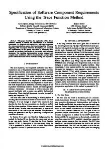
rule-based approach for automated requirements validation that relies on ODL for requirements specification and on a Prolog inference engine [2]. Prolog rules check the requirements model for completeness and consistency, with errors indicated to the user. This paper addresses the design automation component of RDDA. SysML structural block diagrams that describe relations between components and interfaces are saved to XMI format, then converted to ODL and loaded into the knowledge base in a format that is better suited for inference with logical programming tools, such as a Prolog engine (SWI-Prolog [3]). Once the ODL product requirements models, the SysML block diagrams, and ODL component descriptions are loaded into the knowledge base, a set of design rules synthesize a component-based structure centered on the required interfaces and features. Component selection is further refined to satisfy the numeric QoS and resource constraints demanded by the product requirements. Our approach supports static descriptions of features and constraints, such as “8MP resolution“ for an image sensor, or “10 m maximum location error” for a GPS chip. Constraints on compatibility of dynamic behavior is not currently addressed by our framework, though support for it could be added using SysML/UML sequence or state machine behavior diagrams. The methodologies described in this paper assist the system designer in the early stages of the product development process and facilitate an incremental and iterative approach for requirements specification, validation, and partially automated architecture design. To exemplify the RDDA framework the paper uses a case study for a location-enabled mobile system that will be detailed throughout the remaining sections of the paper. Our approach is general enough to incorporate various types of systems; the only change that would need to be addressed is the description of the new domain concepts in terms of the ODL language, i.e. creating a new ODL domain ontology. This paper continues in the next section with a description of the RDDA framework architecture. Section III describes the architecture synthesis based on components that satisfy the features and constraints required by the system under design. Section IV describes related work, while section V summarizes conclusions and discusses future work. II. RDDA FRAMEWORK ARCHITECTURE We start this section by describing the RDDA framework architecture shown in Figure 1 below.
SysM/UML Models XMI Translation Rules: SysML XSL File
Translation Rules: UML/SysML XSL File
Ontology Extraction (XSLT Processor)
Requirements Ontologies ODL/OWL
Ontology Extraction (XSLT Processor)
UML Structure Ontologies ODL/OWL
(Rhapsody)
Design
Component Annotations Ontologies ODL/OWL
INPUT
Requirements SysML Models XMI
SysML Editor
SysML Modeler
Req. Validation Rules
Model Errors
Knowledge Base
Reasoner
Project Toolset (Prolog, Java)
Component Configuration XML
Requirements Specification
Translation Rules: ODL/OWL XSL File
UML Structure Ontologies ODL/OWL
Architecture Synthesis Rules
Synthesized UML 2.0 Models XMI
OUTPUT Model Translator (XSLT Processor)
Fig. 1. Requirements-Driven Design Automation framework architecture.
With its two workflows, the requirements workflow, and the design workflow, the RDDA framework supports roundtrip design engineering as follows. In the requirements workflow, the requirements expert specifies requirements models with a modeling tool and uses RDDA to verify the specification for correctness. Omissions and inconsistencies are indicated to the user, who can correct the errors. This flow is described in our previous article [2]. In the design workflow, the designer uses the RDDA framework to build a component-based architecture that satisfies a validated requirements model generated from the initial requirements model. Architecture models synthesized or completed with RDDA can be fed back into the system and used for building ever more complex structures that satisfy a growing set of requirements in an iterative design process. In detail, the requirements workflow starts with the user modeling requirements using SysML. This visual modeling language derived from UML provides several types of diagrams that are useful for representing requirements, including the Requirements Diagram that captures the textual description of requirements. In [2] we present requirements diagrams for a location-based system design. The text of an ODL requirement statement follows a grammar with a syntax that enables RDDA to extract its semantics. After requirements from the current design iteration have been described, the SysML modeler (in our case IBM’s Rhapsody [5]), will export the requirement model into XMI [6], the standard format for interchanging SysML/UML models. The XMI file with SysML models is converted to OWL files using XSLT [7]. The OWL files comply with the ontology that defines the OPP Design Language, described at the end of this section. OWL statements that specify requirements are converted to Prolog facts that are loaded into the knowledge base. Based on a set of rules, the Prolog reasoner validates the requirements, searching for completeness and consistency errors. If such errors exist, they are highlighted to the user who can go back into the SysML Editor, repair the requirements, and possibly add more, thus closing the requirements workflow cycle.
The design workflow implements a methodology for component selection and architecture synthesis based on semantic component descriptions and validated requirements model. The first part of the workflow starts with describing the components using a Block Definition Diagram available in SysML. This diagram is similar to a UML class diagram and we use it to model components (classes), interfaces, and the relationships between them. The user adds semantic annotations to these components in the same ODL language used for requirements, expressing provided/required features and constraints on QoS and resources. These structural diagrams are next exported into XMI, and then converted to OWL ODL ontology files by means of XSLT. The main step in this workflow, that implements design automation, is the synthesis of component-based SysML block diagrams and the selection of components that satisfy the initial requirements and constraints. This step is described in more details in the next section. The ODL vocabulary is used for describing concepts related to requirements and components, in terms of product decomposition into applications and subsystems, hierarchy of structural features, constraints (such as QoS and system resources), and requirement management (dependencies, tracking, versioning). The OWL ontology that describes the ODL vocabulary defines taxonomy, and relationships between instances. The ODL metamodel ontologies are developed with Protégé [7]. The extensibility of the ODL OWL metamodel is achieved through the OWL import feature, implying that third-party ontologies can be pulled into RDDA's existing metamodel over the internet. III. Component selection and architecture synthesis The fist step in the component selection process is to define a prototype component diagram, as shown below for the location-enabled system we use as example. The block diagram from Figure 2 describes a simplified structural model for a cell phone with a GPS and a camera subsystem. The diagram specifies the interfaces that are implemented by components (blocks) and the interfaces “used” by components.
Fig. 2. Initial Component Diagram for a cell phone product with camera and GPS.
An interface defines the set of operations, their input and output parameters and is identified by a name. The SysML and UML notation for interfaces is the rectangular block with the «interface» stereotype. For example, the Phone component implements the iPhone interface, and at the same time, it requires the iCamera and iGPS interfaces. These two interfaces are provided by the Camera and GPS components, respectively. The Camera component requires the iImageEncoder interface that is provided by two components, namely Canon and Olympus. The GPS component requires the iLocationService interface provided by SiRF and TI components. The completion of the system architecture for this example is formulated as a goal for design automation: selecting between Canon and Olympus the component that will end up in the final architecture design providing the iImageEncoder interface. Similar, the system must select the provider of the iLocationService interface between components SiRF and TI. Since there is more than one component available for these interfaces, the option on which to choose depends on the features and constraints required by “client” requester components and provided by other components in the diagram. This information is currently not captured or used by SysML or UML modeling tools for assisting users and therefore they must consult extensively component documentation before making the selection to make sure all requirements and constraints are satisfied. RDDA captures these as semantic annotations to model concepts (classes, blocks, components, interfaces). The UML Object Constraint Language has the ability to represent arbitrary constraints, but its generality also makes it difficult to use as input with an inference engine. As described in Section II, the SysML structure diagrams are exported to XMI. Through a set of transformations written in XSLT, the models are translated into OWL ODL. For example, the ODL part that describes
the association relationship between the Phone component and the iGPS interface is listed in Figure 3.
Figure 3. ODL OWL representation of the association relationship between the Phone component and the iGPS interface, as converted from SysML XMI.
Loading the resulted OWL files into the Prolog would populate the knowledge base with triplets in the form of (S, P, O), or (subject, property, object). Such a representation is inconvenient to work with; for this reason, the triplets are converted to a more processable representation, namely P(S, O). After this transformation, the knowledge base that will be loaded into Prolog is shown below:
A component CR uses a set of components SC in a design synthesis solution if all constraints stated by CP as required are provided and satisfied by components from SC and its transitive closure on the “require/provides interface” relationships. The design synthesis goal is expressed as a Prolog query. Finding a feasible solution relies heavily on pruning unfeasible search paths and on backward chaining to backtrack from component configurations that cannot satisfy all constraints.
Figure 4. Prolog facts in the KB listing SysML block diagram, feature and constraint facts.
For readability, XML namespaces coming from the XMI export are removed from symbol names. The relationships between component and interfaces from the diagram in Figure 2 are also specified in the KB by the comp(Comp), compReq(Comp, Interface), compProv(Comp, Interface) facts. In addition, the features and constraints detailed in SysML requirements diagrams from [2] are converted to facts to be processed by RDDA. The objective of the design synthesis step is to build a new composite component (a SysML internal block diagram or a block definition diagram) that implements a set of desired interfaces, and provides features and satisfies constraints. Formally, this problem can be formulated as searching for a subgraph in a graph formed by architecture elements (nodes: components, interfaces; edges: “uses” and “implements” relationships), features (nodes: features, edges: “requires”, “provides”), and constraints (nodes: constraint types, edges: “requires”, “provides”, annotated with numeric constraints).
A high-level description of the synthesis algorithms steps follows: 1. Find a component subgraph that matches architectural constraints (interfaces required/ provided). 2. Check if the required features and constraints have been met by the components from the previous step. If not, backtrack to step 1. 3. If there are features or constraints not provided by the components in the solution, check if there are other components that provide those missing features. 4. Return a list S of edges as functors ci(CR, I, CP), where CR is the component that requires interface I that is provided by the component CP. Furthermore, return a list of features as functors cpf(CR, F, CP) that have not been met by components in S, but which are satisfied by components that are not part of S; CR is the component that requires feature F which is provided by component CP that is not part of S. In addition, return a list of required features that are not provided by any existing component. Similar lists are returned for constraints. If during the initial search, our algorithm finds a component that provides a particular needed interface, but which does not satisfy the required features or constraints, the algorithm will backtrack and search for another candidate. Each step above contains one or more procedures, or Prolog rules. For example, for step 2, to check if the required features and constraints have been met, we have the rule in Figure 5.
Fig. 5. Prolog procedure that checks if the required features and constraints have been met.
The method above uses two additional procedures, featuresNotMet/4, and constraintsNotMet/4 that check for those features and constraints that were not satisfied by the current solution components. Part of step 3 is implemented by the whoProvMissQoS rules that check to see if the missing
constraints that were not satisfied by the components in the solution from step 1, are satisfied by other existing components. The code is shown in Figure 6.
Fig. 6. Prolog procedures that check for components that provide unsatisfied constraints.
The QoS constraints are given as acceptable [min, max] intervals for some component parameter. A constraint example is (gps, qosLocationError, 0, 5), where the gps component requires a location error smaller than 5. The rule checks to see if there is a component that provides the qosLocationError constraints and for which the minimum and maximum values are contained in the required interval. Constraint
verification uses Prolog's Constraint Logic Programming (CLP) #>= operator for checking numeric ranges. Our algorithm also handles global additive constraints, such as the maximum cost or weight allowed. Validating designs for an additive constraint finds all components from the solution that provide that constraint, adds all provided values and checks against the required value. The rules for additive constraints are shown in Figure 7.
Fig. 7. Prolog rules for checking if cumulative constraints have been met.
The design synthesis algorithm will find all component designs that satisfy the architecture constraints (interfaces required/provided), beginning with the ones for which all features and constraints are satisfied. Hence, if there are such solutions, they are used to generate an internal block diagram in XMI that can be loaded back into the SysML modeling tool. Returning to the phone example, the algorithm is run like this to generate a structural diagram for a component that provides the iPhone interface and satisfies all requirements: :- buildArch(X, [iPhone]). the first solution returned in X will be a tuple of functor lists [ci(camera, iImageEncoder, canon), ci(gps, iLocationService, ti), ci(phone, iCamera, camera), ci(phone, iGPS, gps), ci(dummy, iPhone, phone)], [], [], [], []. The ci() functors contain the edges from
the solution architecture, . The diagram for this solution is shown in Figure 8. Another solution, but that does not provide all feature and constraints is [ci(camera, iImageEncoder, olympus), ci(gps, iLocationService, sirf), ci(phone, iCamera, camera), ci(phone, iGPS, gps), ci(dummy, iPhone, phone)], [cpf(gps, fProximityService, ti), cpf(camera, fGIFImageFormat, canon)], [], [cc(qosLocationError, ti)], []. It can be seen that
feature fProximityService required by the gps component is not provided by the sirf component that is part of the solution, but is actually provided by the ti component which in this particular case, is not part of the solution. In addition, the qosLocationError constraint is not met by the sirf component, which has a maximum location error value of 7, while at most 5 is required. The algorithm will find the component that satisfies this constraint (in our case the ti component) and will return it to the user.
After the best solution is chosen, trivial transformation from Prolog → OWL → XMI is achieved. The resulting XMI file is loaded back into the SysML modeling tool for further development.
Fig. 8. Block diagram for the feasible design synthesis solution.
We note that a partial solution component diagram can be supplied as input to the buildArch() procedure. Any complete feasible solutions found will include the initial set of components. We are aware that the current algorithm does an exhaustive search if a feasible solution is not found. We chose this deliberately, to give designers options for partial structural diagrams that miss features, or for features/constraints that cannot be met. IV. RELATED WORK The RDDA design synthesis methodology is related to efforts for automating web service composition. The use of Semantic Descriptions is proposed in [9] for finding, filtering, and integrating Web Services. Because existing service description techniques with WSDL and SOAP are insufficient the authors use Semantic Web specifications and
an inference engine to store information about services and to find matching services, as well as to implement a composer for interfacing the user with the inference engine. Our project achieves similar objectives and in addition deals with verification of consistency for requirements models and the generated structure diagrams. Similar to the previous paper, ontologies have been applied in [10] to a different area, Software Patterns. The authors introduce the concept of ONTOPATTERN, an ontology that incorporates knowledge about the description and localization of patterns. Because patterns are included as instances of classes in the ontology, ONTOPATTERN becomes a knowledge base where inferences and searches can be made seemingly, aiding the reuse of patterns. The authors in [9] and [10] have employed ontologies in specific domains, Web Services and Patterns, reducing the time for selection and configuration. In contrast, in RDDA we propose a topdown methodology, instead of a bottom-up approach. We propose ontology-based SysML/UML architecture synthesis from requirements and component specification. A software engineering tool called CASSANDRA is described in [11]. This assists and guides developers through the software development process. It is implemented in WINPROLOG and has different interface agents and application agents that adapt to various external applications and CASE tools. The proposed tool goes through the processes of Analysis, Design, Construction, and Project Management. The result is an implementation that consists of the application that is tested and ready to run. The authors in [12] propose a framework called Semantic Streams in which a user can take advantage of declarative statements to query a sensor network. The principles from the service and semantic domains are combined here to form a semantic services programming model where each service is a process that deduces semantic data about the world. These services are converted to rules with pre- and postconditions and the inference engine uses backward chaining to match every element of the query with the post-condition of a service. In our approach, we follow a similar path for architecture synthesis. In [13], the authors present an approach for the representation and management of requirements, representation, and synthesis of system architectures from reusable component specifications, together with the validation and verification of the system architecture based ontologies and reasoning. The work is concentrated around a software prototype called Paladin that supports component and requirements specification. Paladin is integrated with Ontology-Based Rule Checking, thus resulting in the architecture composed of components and functions. To reuse objects and sub-systems, a combination of top-down decomposition mixed with bottom-up synthesis has been employed. The decomposition is achieved by decomposing the higher-level requirements into lower level, more specific and detailed requirements, thus influencing the overall system design. The synthesis takes place by coupling the right components, testing, and verifying the architecture and, in the end, delivering the final product. V. CONCLUSIONS In this paper, we described a methodology for architecture synthesis driven by requirements and constraints. Starting with the SysML model that describes the existing components
and how they relate to one another in terms of interfaces required and provided, we populate a Prolog knowledge base with facts. A set of rules are applied on the knowledge base, resulting a diagram with a subset of components that satisfy the interfaces, required features, and constraints. The list of components is presented to the user as a new SysML block diagram. Our approach takes into consideration the case when there are specific features or constraints that cannot be satisfied by the components that are part of the solution, thus making our methodology general and realistic. These mechanisms are part of the RDDA framework that develops methodologies for system design automation based on requirements and components descriptions. Our framework has the necessary capability of integrating with a SysML/UML modeling tool. In the component selection area, we will improve in the future the selection mechanisms by halting whenever a optimal solution (where all features and constraints have been met) has been found. Furthermore, we will consider modeling the behavioral part of a system, by using specific SysML diagrams. A long-term goal is to integrate all tools for requirements modeling and validation, component selection, and design composition, into a common platform based on Eclipse. REFERENCES [1] Ionut Cardei, Mihai Fonoage, Ravi Shankar. Framework for Requirements-Driven System Design Automation. In The 1st IEEE Systems Conference, Hawaii, USA, April 2007. [2] Ionut Cardei, Mihai Fonoage, Ravi Shankar. Model Based Requirements Specification and Validation for Component Architectures. In The 2nd IEEE International Systems Conference, Montreal, QC, Canada, April 2008. [3] SWI-Prolog: Prolog environment. http://www.swi-prolog.org/. [4] SysML: systems modeling language. http://www.omgsysml.org/. [5] IBM Rhapsody: UML and SysML based Model Driven Development environment. http://www-01.ibm.com/software/awdtools/rhapsody/. [6] XMI: XML metadata interchange language. http://www.omg.org/technology/documents/formal/xmi.htm. [7] XSLT: language for transforming XML documents into other XML documents. http://www.w3.org/TR/xslt. [8] Protégé: ontology editor and knowledge-base framework. http://protege.stanford.edu/. [9] Evren Sirin, James Hendler, Bijan Parsia. Semi-automatic Composition of Web Services using Semantic Descriptions. In Web Services: Modeling, Architecture and Infrastructure workshop in ICEIS 2003, Angers, France, April 2003. [10] Rosario Girardi, Alisson Neres Lindoso. An Ontology-based Knowledge Base for the Representation and Reuse of Software Patterns. In ACM SIGSOFT Software Engineering Notes, v.31 n.1, January 2006. [11] Markus Schacher. CASSANDRA: An Automated Software Engineering Coach. http://www.knowgravity.com/pdfe/CASSANDRA%20Overview%202001.pdf. [12] Kamin Whitehouse, Feng Zhao, Jie Liu. Semantic Streams: a Framework for Declarative Queries and Automatic Data Interpretation. Tech. report MSR-TR-2005-45, Microsoft Research, 2005. [13] Vimal Mayank, Natalya Kositsyna, Mark Austin. Requirements Engineering and the Semantic Web: Part II. Representation, Management, and Validation of Requirements and System-Level Architectures. Technical Report. TR 2004-14, University of Maryland , 2004.