... The Netherlands. Email: {m.dossantossoares, j.l.m.vrancken}@tudelft.nl ... by a list of user requirements for a road traffic management system. Index Termsâ ... is good Software Engineering practice, as requirements should be written at ...
JOURNAL OF SOFTWARE, VOL. 3, NO. 6, JUNE 2008
57
Model-Driven User Requirements Specification using SysML Michel dos Santos Soares, Jos Vrancken Faculty of Technology, Policy and Management, Delft University of Technology, Delft, The Netherlands Email: {m.dossantossoares, j.l.m.vrancken}@tudelft.nl
Abstract— Requirements engineering is an important phase in a system’s life cycle. When poorly performed, various problems may occur, such as failures, cost overrun and delays. The increasing complexity of systems makes requirements engineering activities both more important and more difficult. Model-driven engineering, in which models are the main artifact during system development, is an emergent approach that tries to address system complexity by the intense use of models. This article proposes a model-driven approach to requirements engineering based on SysML Requirements and Use Case Diagrams. The main advantages are that user requirements are graphically modeled, their relationships are explicitly mapped, and system decomposition is considered in the early system development activities. In addition, requirements traceability is enhanced by using the SysML Requirements tables. The approach is illustrated by a list of user requirements for a road traffic management system. Index Terms— Requirements Engineering, Model-driven Engineering, SysML, UML
I. I NTRODUCTION Requirements for a system are a collection of needs expressed by stakeholders respecting some constraints under which the system must operate. Requirements can be classified in many ways [1]. The first classification used in this paper is related to the level of detail. In this case, the two classes of requirements are user or system requirements [2]. User requirements are highlevel abstract requirements based on end users and other stakeholders viewpoint. They are usually written using natural language, occasionally with the help of domain specific models or even informal models not related to any method or language [3]. The fundamental purpose of user requirements specification is to document the needs and constraints gathered in order to later develop a system based on those requirements. Systems requirements are derived from user requirements but with a detailed description of what the system should do, and are usually modeled using formal or semi-formal methods and This paper is an extended version of the paper “Requirements Specification and Modeling through SysML,” by Michel dos Santos Soares and Jos Vrancken, which appeared in the Proceedings of the IEEE International Conference on Systems, Man, and Cybernetics SMC 2007, pp. 1735-1740, ISBN 1-4244-0991-8 Montreal, Canada. c 2007 IEEE. ° This work was supported by the Next Generation Infrastructures Program and the Next Generation Infrastructures Research Center of Delft University of Technology.
© 2008 ACADEMY PUBLISHER
languages. This proposed classification allows the representation of different views for distinct stakeholders. This is good Software Engineering practice, as requirements should be written at different viewpoints because different stakeholders use them for distinct purposes. The process by which requirements for systems and software products are gathered, analyzed, documented and managed throughout the development life cycle is called Requirements Engineering (RE) [2]. RE can be divided into two main groups of activities [4]: i) requirements development, including activities such as eliciting, documenting, analyzing, and validating requirements, and ii) requirements management, including activities related to maintenance, such as tracing and change management of requirements. This paper is related to user requirements development, mainly the activities of documenting and analyzing requirements for software systems. The assumption is that improving requirements development activities may have a strong impact on the quality of later requirements activities, such as requirements tracing. It is assumed that user requirements were already gathered using one or more of a variety of proposed techniques, such as interviews, questionnaires or ethnography, and transformed into a list of requirements according to each stakeholder’s viewpoint. RE is generally considered in the literature as the most critical process within the development of complex systems [5], [6]. Software intensive systems [7], such as large-scale heterogeneous systems and embedded systems used in domains such as telecommunications, business and transportation, are complex systems difficult to model, design and analyze. In these systems, software interacts with other software, systems, devices, sensors, actuators, and with people. Their complexity is increased due to the large number of elements and reliability factors. Thus, they must be decomposed into several smaller components in order to manage complexity and facilitate their implementation and verification. In addition, there is a need to increase the level of abstraction, hiding whenever possible unnecessary complexity, by the intense use of models. Models are abstractions of physical systems that allow one to reason about the system by ignoring irrelevant details while focusing on the relevant ones [8]. This simplification (or abstraction) is the essence of modeling [9]. Models are used in many activities, such as to
58
predict system behavior, as technical specifications and to communicate design decisions to various stakeholders. Although code can also be considered a model, as it abstracts lower-level machine related instructions, in practice code and models are often considered to be different types of artifacts. Typically, in Systems and Software Engineering, an artifact is considered to be a model if it has a graphical representation instead of only a textual one as in the case of source code [10]. This comes as no surprise, as UML and its profiles are the current dominant graphical languages used in model-driven approaches. Several researchers are working on the transitions from code-only to model-driven approaches in order to increase the level of abstraction [11], [12], [13]. The common feature to all these approaches is that models are the primary system and software artifacts, being as important as they are in other engineering disciplines, and are specified in higher levels of abstraction using well-defined languages [14]. However, few attempts consider models as centric artifacts in RE. A. Proposed approach Well-written user requirements documentation is fundamental as it facilitates later phases, not only during RE, but during the whole system life cycle. This paper is about applying a Model-Driven Requirements Engineering approach based on SysML [15] Requirements and Use Case diagrams. First, a classification for each atomic requirement is proposed, avoiding the confusion of which type of requirement is written in the user requirements document. Then, the SysML Requirements diagram is used to represent graphically single user requirements and their relationships. The idea is that user requirements are modeled after being written in natural language. The SysML Requirements Diagram specifies a defined semantics to be followed when relating requirements to each other and to other models created during system design. Requirements may be combined depending on their semantics, what can be useful for early discovering subsystems and start delimiting system architecture. User requirements are also represented in a tabular format, which may facilitate requirements tracing during the system life cycle. This is important to know what happens when related requirements change or are deleted, which improves traceability. Finally, SysML Use Case diagrams are applied to represent the actors involved and the use cases, giving a context diagram delimiting the system. Then, use cases are related to SysML Requirements using one of the proposed relationships. Although the idea is to use models from the early phases of system development, natural language is still important and can be used as input for later RE activities. Despite its problems, there are also advantages, as natural languages are the primary communication medium towards stakeholders. © 2008 ACADEMY PUBLISHER
JOURNAL OF SOFTWARE, VOL. 3, NO. 6, JUNE 2008
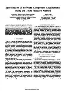
After being structured and graphically represented (Fig 1) using SysML Requirements and Use Case diagrams, user requirements may be detailed into systems requirements, being specified using other models, such as other UML/SysML diagrams or formal methods. SysML Requirements Diagram
informal diagrams
domain specific diagrams
natural language requirements
SysML Requirements Tables
+ explicit relationships between - requirements - requirements and use cases + improved - structure - traceability + graphical representation
SysML Use Case Diagram
structured user requirements represented as models and in a tabular format
+ less ambiguity + system delimitation + methodology freedom
Figure 1. SysML
Model-Driven Requirements Engineering approach with
B. Related Work Studies conducted by the Standish Group [16] and other researchers [17], [18] found that the main factors for problems with system projects (cost overruns, delays, user dissatisfaction) are related to requirements issues, such as lack of user input, incomplete requirements specifications, uncontrolled requirements changing and unclear objectives. In an empirical study [3], the activities of identify user requirements and later model these requirements were considered as priorities by a large percentage of respondents. In addition, according to Brooks [19], knowing what to build, which includes requirements elicitation, technical specification, and prioritization, is the most difficult Systems Engineering phase in the life cycle. Related work of two RE activities are given as follows. 1) Requirements Documentation: There are several approaches to document requirements. Basically, they can be classified as graphic-based, purely textual, or a combination of both. Some are generic while others are based on a specific methodology. The most common approach is to write user requirements using natural language, which may cause several problems such as imprecision, misunderstandings, ambiguity and inconsistency [20]. This problem gets more serious as requirements are written in more detail in order to be used as system specifications. With the purpose of giving more structure and pattern to requirements documents, structured natural language is used [21]. Nevertheless, structured natural language is neither formal nor graphical, and can be too much oriented to algorithms and specific programming languages. User Stories have been used as part of the eXtreme Programming (XP) [22] agile methodology. They are written by the customer using non-technical terminology, in the format of some sentences using natural language. Although XP offers some advantages in the RE process, such as user involvement and defined formats for user
JOURNAL OF SOFTWARE, VOL. 3, NO. 6, JUNE 2008
requirements and tasks, requirements are still loosely related, not graphically specified, and oriented to a specific methodology. Even before UML emerged as the main Software Engineering modeling language, Use Cases were already a common practice for graphically representing functional requirements in other methodologies, such as ObjectOriented Software Engineering (OOSE) [23]. Their popularity can be explained due to their simplicity, acting as a bridge between technical and business stakeholders, the compact graphical nature to represent requirements that may be expanded to several pages, and even as a basis for managers when doing project estimation [24] [25]. Use cases also have some disadvantages and problems [26]. They are applied mainly to model functional requirements, however are not very helpful to model other types of requirements, such as non-functional ones [27]. Use Case diagrams lack well-defined semantics, which may lead to differences in interpretations by stakeholders. For instance, the include and extend relationships are considered similar, or even the inverse of each other [28]. In addition, use cases may be misused, when too much detail is added, which may incorrectly transform the diagrams into flowcharts or making them difficult to comprehend. Finally, although being an important part of an object-oriented language, the diagram itself is not object-oriented. 2) Requirements Relationships: It is well-known by Software Engineering researchers and practitioners that requirements are related to each other. These interactions affect various software development activities, such as release planning, change management and reuse. A study has shown that the majority of requirements are related to or influence other requirements [29]. Due to this fact, it is almost impossible to plan systems releases only based on the highest priority requirements, without considering which requirements are related to each others and the type of these relationships. Many requirements relationships are presented and classified as structural, constrain or cost/value in [30]. The survey [31] introduces the discipline of Requirements Interaction Management (RIM), which is concerned with the analysis and management of dependencies among requirements. Among the main activities of the RIM discipline, the ones that are related to this article are the representation of requirements and their interactions. This is done using the SysML Requirements diagrams and tables. II. A P ROPOSED U SER R EQUIREMENTS C LASSIFICATION A common classification proposed for requirements in the literature is based on the level of abstraction, in which requirements are classified as functional or non-functional [32]. Functional requirements describe the services that the system should provide, including the behavior of the system in particular situations. Nonfunctional requirements are related to emergent system © 2008 ACADEMY PUBLISHER
59
properties such as safety, reliability and response time. These properties cannot be attributed to a single system component. Rather, they emerge as a result of integrating system components. Non-functional requirements are also considered as quality requirements, and are fundamental to determine the success of a system. The IEEE Recommended Practice for Software Requirements Specifications [33] suggests a table of contents of a Requirements Specification with the following requirements items: external interfaces, functions, performance, logical database, design constraints, and software system attributes. For sake of simplicity, and as some of the items can be considered non-functional requirements (performance, design constraints and software system attributes), or functional requirements (logical database), the second classification used in this paper (after user vs. system requirements) is as follows: • Functional: describes what the system should do to be useful within the stakeholders’ context (the functionalities), including information about logical databases, such as frequency of use, data entities, and integrity constraints. • Non-functional: are related to emergent system properties, such as reliability and performance. These requirements do not have simple yes/no satisfaction criteria. Instead, it must be determined whether a non-functional requirement has been satisfied. • External: a detailed description of all inputs into and outputs from the software system, such as system, user, hardware, software and communication interfaces. It is an important classification to decompose the system into subsystems. III. U SER R EQUIREMENTS S PECIFICATION USING S YS ML D IAGRAMS SysML is a systems modeling language that supports the specification, analysis, design, verification and validation of a broad range of complex systems [15]. The language is an evolution of UML 2.0 [34] to be applied to systems that may include hardware, software, information, processes and personnel. This may facilitate the communication between heterogeneous teams (for instance, mechanical, electrical and software engineers) that work together to develop a system. The language is effective in specifying requirements, structure, behavior, allocations of elements to models, and constraints on system properties to support engineering analysis. Both SysML and UML languages are based on the same metametamodel, the OMG Meta Object Facility (MOF) [35]. SysML is considered both a subset and an extension of UML 2.0. As a subset, UML diagrams considered too specific for software (Objects and Deployment diagrams) or redundant (Communication and Time Diagrams) were not included in SysML. Some diagrams are derived from UML without significant changes (Sequence, State-Machine, Use Case, and Package Diagrams), some are derived with changes (Activity, Block Definition, Internal Block Diagrams) and there are two
60
new diagrams (Requirements and Parametric Diagrams). As a matter of fact, SysML is compatible with UML, which can facilitate the integration of the disciplines of Software and System Engineering. SysML can be used in many important activities during the system life cycle. The following list gives some examples: a) Communication with Stakeholders: Requirements are normally presented to stakeholders using natural language. SysML provides two diagrams for RE: Use Cases and Requirements Diagrams. These diagrams are useful to improve requirements visualization by using graphical elements. b) Improving system knowledge: The application of visual models during system engineering development facilitates system understanding, and allow standards and patterns that can be used and reused. c) Model execution and verification: Model-driven transformations from SysML semi-formal diagrams (Sequence, State-Machine, Activity Diagrams) to a formal method such as Petri nets [36], allows not only formal verification but also model execution using simulation. These practices may help in early discovering possible design problems. d) Documentation for maintenance: Several factors contribute to the necessity of performing system maintenance, such as new requirements, bug fixing or new constraints (new laws for instance). The changes are necessary in order to keep the system useful. In fact, it is unlikely that the system will not undergo any changes. SysML models document design decisions, which are useful when the development team needs to perform changes. SysML may be useful even if there is a need to perform the reengineering of legacy systems with poor documentation. The following subsections presents SysML diagrams for RE. A. The SysML Requirements Diagram The SysML Requirements diagram helps in better organizing requirements, and also shows explicitly the various kinds of relationships between different requirements. Another advantage of using this diagram is to standardize the way of specifying requirements through a defined semantics. As a direct consequence, SysML allows the representation of requirements as model elements, which mean that requirements are part of the system architecture [13]. The SysML requirements constructs are intended to provide a bridge between traditional requirements management tools and the other SysML models. When combined with UML for software design, the requirements constructs can also fill the gap between user requirements specification, normally written in natural language, and Use Case diagrams, used as initial specification of system requirements. A SysML requirement can also appear on other diagrams to show its relationship to other modeling elements. With the SysML Requirements diagram, visualization © 2008 ACADEMY PUBLISHER
JOURNAL OF SOFTWARE, VOL. 3, NO. 6, JUNE 2008
techniques are applied from the early phases of system development. The SysML Requirements diagram is a stereotype of the UML Class diagram, as shown in Fig. 2.
Figure 2. Basic SysML Requirements diagram
B. Requirements relationships Implementing all requirements in a single system release may be unattractive due to the high costs involved, lack of sufficient staff and time, and even client and market pressures. These difficulties make prioritization a fundamental activity during the RE process. Prioritizing requirements is giving an indication of the order in which the requirements should be considered for implementation. However, it is not always possible to plan a system release based only on the set of more important requirements due to requirements relationships. A better knowledge of requirements relationships may be useful to do more accurate release plans, to reuse requirements and to drive system design and implementation. The SysML Requirements diagram allows several ways to represent requirements relationships. These include relationships for defining requirements hierarchy, deriving requirements, satisfying requirements, verifying requirements and refining requirements. The relationships can improve the specification of systems, as they can be used to model requirements. The relationships: hierarchy, derive, satisfy, verify, refine and trace are briefly explained below. In large, complex systems, it is common to have a hierarchy of requirements, and their organization into various levels helps in dealing with system complexity. For instance, high-level business requirements may be gradually decomposed into more detailed software requirements, forming a hierarchy. SysML allows splitting complex requirements into more simple ones, as a hierarchy of requirements related to each other. The advantage is that the complexity of systems is treated from the early beginning of development, by decomposing complex requirements. The concept of hierarchy also permits the reuse of requirements. In this case, a common requirement can be shared by other requirements. The hierarchy is built based on master and slave requirements. The slave is a requirement whose text property is a read-only copy of the
JOURNAL OF SOFTWARE, VOL. 3, NO. 6, JUNE 2008
text property of a master requirement. The master/slave relationship is indicated by the use of the copy keyword. The derive relationship relates a derived requirement to its source requirement. During RE activities, new requirements are created from previous ones. Normally, the derived requirement is under a source requirement in the hierarchy. In a Requirements diagram, the derive relationship is represented by the keyword deriveReqt. The satisfy requirement describes how a model satisfies one or more requirements. It represents a dependency relationship between a requirement and a model element, such as other SysML diagrams, that represents that requirement. This relationship is represented by the keyword satisfy. One example is to associate a requirement to a SysML Block diagram. The verify relationship defines how a test case can verify a requirement. This includes standard verification methods for inspection, analysis, demonstration or test. For example, given a requirement, the steps necessary for its verification can be summarized by a state-machine diagram. The keyword verify represents this relationship. The refine relationship describes how a model element (or set of elements) can be used to later refine a requirement. For example, how a Use Case can represent a requirement in a SysML Requirements diagram. The relationship is represented in the diagram by the keyword refine. The trace relationship provides a general purpose relationship between a requirement and any other model element. Its semantics has no real constraints and is not well-defined as the other relationships. For instance, a generic trace dependency can be used to emphasize that a pair of requirements are related in a different way not defined by other SysML relationships [37]. C. Requirements Table Requirements traceability is one important quality factor in systems design. A definition of requirements traceability is given in [38] as: “the ability to describe and follow the life of a requirement, in both a forward and backward direction, i.e., from its origins, through its development and specification, to its subsequent deployment and use, and through periods of ongoing refinement and iteration in any of these phases”. Basically, requirements traceability helps in identifying the sources, destinations and links between requirements and models created during system development. Identifying and maintaining traces between requirements are considered important activities during RE [39]. The activity of requirements tracing is very useful, for example, to identify how requirements are affected by changes. For instance, in later phases a requirement may be removed, and the related requirements may be also deleted or reallocated. And when a requirement is changed, the stakeholders need to know how this change will affect other requirements. Traceability also provides a possibility to ensure that all requirements are fulfilled by the system and subsystem components. As a matter © 2008 ACADEMY PUBLISHER
61
of fact, important decisions on requirements and the correspondent models are better justified [40]. One way to manage the requirements traceability in SysML is within requirements tables. TABLE I. A S YS ML H IERARCHY R EQUIREMENTS TABLE Id
Name
Type
SysML allows the representation of requirements, their properties and relationships in a tabular format. One proposed table shows the hierarchical tree of requirements from a master one. The fields proposed for table I are the requirement ID, its name and type. There is a table for each requirement that has child requirements related by the relationship “hierarchy”. TABLE II. A S YS ML R EQUIREMENTS RELATIONSHIP TABLE Id
Name
RelatesTo
RelatesHow
Type
Other information items can be represented, as shown in table II. For example, the requirement Id, the name of the requirement, to which requirement it is related (if any), the type of relationship and the requirement type. This allows an agile way to identify, prioritize and trace requirements. As a matter of fact, whenever a requirement is changed or deleted, the tables are useful to show that this can affect other requirements. D. The SysML Use Case Diagram The SysML Use Case diagram is derived without important extensions from the UML 2.0 Use Case diagram. The main difference is the more wide focus, as the idea is to model complex systems that involve not only software, but also other systems, personnel, and hardware. The Use Case diagram shows system functionalities that are performed through the interaction of the system with its actors. The idea is to represent what the system will perform, not how. The diagrams are composed of actors, use cases and their relationships. Actors may correspond to users, other systems or any external entity to the system. There are four types of relationships in a Use Case diagram: communication, generalization, include and extend. The “communication” relationship is used to associate actors and use cases when they effectively participate in the use case behavior. The “generalization” relationship occurs from actor to actor or from use case to use case. The semantics is the same used in other diagrams, such as the UML Class diagram: the child element inherits all behavior of its parent, and can add some more specific behavior. The “include” relationship provides a mechanism useful when a sequence of events is common to more than one use case. These sequences of events can
62
be encapsulated as one use case and reused by other use cases. The execution of the base use case implies also in the execution of the included use cases. The “extend” relationship provides optional functionality, which extends the base use case at defined extension points under specified conditions. This relationship is useful when a use case is too complex, with many alternatives and optional sequences of interactions. The solution is to separate each alternative or option of the base use case into another use case, and relate them using the “extend” keyword. The base use case is independent of the extended ones, which may only be executed if the condition in the base use case that causes it to execute is set to true. The detailed sequence of events in a use case can be represented by different manners. It is common to describe the sequence of events in structured language based on a pre-defined pattern. One example is given in [41], in which the document has the following fields: Use Case Title, Actors involved, Use Case goal, Precondition, Pos-condition, Steps and Alternatives (the last two are both enumerated lists). Considering a modeldriven approach, it is also possible to specify use case behavior by Activity diagrams [42] or Sequence diagrams [43]. Within SysML, a use case may also be represented by SysML Requirements diagram. Which of these techniques to use depends on the nature of the use case behavior as well as of the intended reader. A combination of techniques can also be used in order to present the best manner to each stakeholder.
JOURNAL OF SOFTWARE, VOL. 3, NO. 6, JUNE 2008
Requirement - Text: String - Id: String
Non-functional Requirement
Functional Requirement
- Type: String
External Interface - Type: String
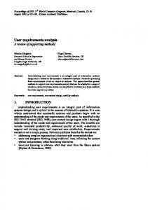
Figure 3. Extension to SysML Requirements Diagram with user requirements classifications
property “type” that may have several tagged values. Examples of possible values are Performance, Security and Efficiency for Non-functional Requirements, and User, Hardware, Software and Communication for External Interface requirements. B. Grouping Requirements By modeling requirements with SysML, system complexity is addressed from the early system design activities. Managing decomposition is an important task to be able to deal with complexity. Requirements may be decomposed into atomic requirements, and may later even be related in the sense that together they are capable of delivering a whole feature, ie., they are responsible for a well-defined subsystem.
IV. S YS ML R EQUIREMENTS D IAGRAM E XTENSIONS The basic SysML Requirements diagram is extended in this section, by creating new stereotypes and tagged values, and by grouping related requirements. A. Stereotypes Stereotypes are the main mechanism used to create profiles and extensions to the SysML metamodel. A stereotype extends a metaclass or another stereotype. Well-known examples of stereotypes for the UML metamodel are the classes control, entity and boundary, each one with its own graphical icon. When used in a Class diagram, these stereotypes improve semantics for the diagram readers. After creating a stereotype, specific properties and constraints can be created. Properties add information to elements of the model, and are normally associated to tagged values. Properties are displayed inside braces, with the tag and the value encoded as strings. Tagged values add extra semantics to a model element. Constraints may also be used as semantics restrictions applied to elements. One example of a constraint is the association of the “xor constraint” specifying a restriction (exclusive or). According to the classification proposed in Section 2, three requirements stereotypes are created: Functional, Non-functional and External Interfaces (Fig. 3). The Nonfunctional and External Interface requirements have the © 2008 ACADEMY PUBLISHER
Figure 4. Grouping Requirements
SysML requirements may be part of other SysML requirements, as a hierarchy. We propose in this subsection that related SysML Requirements can be grouped into a single SysML requirements sub-package (similar to the UML package diagram, which combines several class diagrams), creating categories of requirements (Fig. 4). V. C ASE S TUDY The case study is based on a document with 79 atomic requirements for a road traffic management system. The requirements are based on a series of interviews and studies with stakeholders. The stakeholders (and the relative number of requirements) were classified as: the Road Users (1), the Ministry of Transport, Public Works and Water Management (2), the Traffic Managers (10), the Traffic Management Center (8), the Task, Scenario and Operator Manager (22), the Operators (4), the Designers of the Operator’s Supporting Functions (15), and the Technical Quality Managers (17). We have selected in this paper to model the requirements of the Traffic Manager
JOURNAL OF SOFTWARE, VOL. 3, NO. 6, JUNE 2008
63
and the Traffic Management Center. The Ministry requirements are just written, as they are source for requirements TM4 and TMC14. The requirements are given in the following subsections.
•
A. Requirements
•
1) Ministry of Transport, Public Works and Water Management: • MI2 - The utilization of the road network in the Netherlands must be maximized (optimally utilized). • MI3 - The initial and yearly investment costs of the management of the traffic-flow in the Netherlands must be minimized. 2) Traffic Manager: • TM4 - It is expected that software systems will be increasingly more intelligent for managing the traffic-flow in a more effective and efficient manner. • TM5 - To optimize traffic flow, it is expected that gradually, region-wide traffic management methods will be introduced. • TM6 - The traffic management systems must have a convenient access to region-wide, nation-wide, or even European-wide parameters so that the trafficflow can be managed optimally. • TM7 - It must be possible for the traffic managers/experts to express (strategic) “task and scenario management frames”, conveniently. • TM8 - The system should effectively gather and interpret all kinds of information for the purpose of conveniently assessing the performance of the responsible companies/organizations that have carried out the construction of the related traffic systems and/or infrastructure. • TM9 - The system must support the traffic managers/experts so that they can express various experimental simulation and analytical models. • TM10 - The system must enable the traffic managers/experts to access different kinds of statistical data. • TM11 - The system must enable the traffic managers/experts to access different kinds of data for transient cases such as incidents. • TM12 - The system must provide means for expressing a wide range of tasks and scenarios. • TM13 - The traffic management will gradually evolve from object management towards task and scenario management. 3) Traffic Manager Center: • TMC14 - The operational costs of the traffic management centers and shared resources must be minimized. • TMC15 - The operators’ reaction speed must be improved, especially in critical and unanticipated situations. • TMC16 - The operators’ decision accuracy must be improved, especially in critical and unanticipated situations. © 2008 ACADEMY PUBLISHER
•
•
•
TMC17 - The system must provide means to manage various “traffic management configuration information” conveniently. TMC18 - The system must provide tools so that the operators can perform their work more efficiently. TMC19 - The system must provide tools so that the operators can perform their work more effectively. TMC20 - The system must make it intuitively obvious in which function/context the operator is working in. TMC21 - The education material and process necessary to train the operators must be simplified, standardized and supported. This should improve the effectiveness of tutoring.
B. SysML Requirements Tables Tables III through VII show SysML Hierarchy Requirements tables for requirements TM4, TM7, TM9, TMC14, TMC15 and TMC16. TABLE III. H IERARCHY R EQUIREMENTS TABLE - TM4 Name Region-wide traffic management Traffic flow managed optimally
Id TM5 TM6
Type Functional Functional
TABLE IV. H IERARCHY R EQUIREMENTS TABLE - TM7 Name Simulation and analytical models Wide range of tasks and scenarios
Id TM9 TM12
Type Functional Functional
TABLE V. H IERARCHY R EQUIREMENTS TABLE - TM9 Id TM10 TM11
Name Access statistical data Access transient data
Type Functional Functional
TABLE VI. H IERARCHY R EQUIREMENTS TABLE - TMC14 Id TM15 TM16
Name Improve reaction speed Improve decision accuracy
Type Non-functional Non-functional
TABLE VII. H IERARCHY R EQUIREMENTS TABLE - TMC15, TMC16 Id TM18 TM19
Name Tools perform work efficiently Tools perform work effectively
Type Functional Functional
The other proposed type of table, relating requirements and their relationships for each SysML Requirements diagram is presented in tables VIII and XIX.
64
JOURNAL OF SOFTWARE, VOL. 3, NO. 6, JUNE 2008
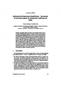
Figure 5. SysML Requirements diagram for Traffic Management Stakeholder
TABLE VIII. S YS ML R EQUIREMENTS RELATIONSHIP TABLE FOR TM Id TM7 TM8 TM13
Name Task and scenario frames Gather and interpret information Object towards task and scenario
RelatesTo {TM5, TM6} TM9 TM12
RelatesHow trace deriveReqt deriveReqt
Type Functional External Functional
TABLE IX. S YS ML R EQUIREMENTS RELATIONSHIP TABLE FOR TMC Id TMC17 TMC20 TMC21
Name Traffic management configuration information Make function/context obvious Education material
© 2008 ACADEMY PUBLISHER
RelatesTo {TMC15, TMC16} {TMC18, TMC19} {TMC18, TMC19}
RelatesHow deriveReqt deriveReqt deriveReqt
Type Functional Functional Functional
JOURNAL OF SOFTWARE, VOL. 3, NO. 6, JUNE 2008
65
Figure 6. SysML Requirements diagram for Traffic Management Center Stakeholder
C. SysML Requirements diagrams The associated Requirements diagrams for the list of user requirements are given by Figs. 5 and 6, respectively concerning the Traffic Manager and the Traffic Management Center requirements. D. SysML Use Case diagrams The associated Use Case diagrams are given by Figs. 7 and 8, respectively concerning the Traffic Manager and the Traffic Management Center requirements. E. Use Case and Requirements Relationship The SysML “refine” relationship can be used to relate requirements to other SysML models. For example, the Requirements sub-package representing requirements TM5 and TM6 can be associated by the refine relationship to the use case “Manage region-wide traffic flow”, which means that the requirements can be represented by the use case. Figure 9 shows this example. Later, this use case can be detailed by including other use cases and relationships, © 2008 ACADEMY PUBLISHER
Figure 7. Use Case diagram for Traffic Manager
or even by using other SysML diagrams, such as the Sequence diagram. As a result, one knows which Sequence diagram models a specific SysML Requirement.
66
JOURNAL OF SOFTWARE, VOL. 3, NO. 6, JUNE 2008
productivity in other environments.
Figure 8. Use Case diagram for Traffic Manager Center
Figure 9. Refine relationship example
VI. D ISCUSSION The gap between the application of new academic methods, techniques and processes in industry is common in all domains. Systems and Software Engineering are no exception. The challenge is not only to develop better theories, but also to implement these theories in practice. Some studies were performed to discover why good RE practices are not widely used in industry [44], [45]. The following items summarizes some well-known obstacles: • RE is often seen as waste of time. Project managers may consider that teams should be more concerned about system design and implementation. • Normally, it takes a long time before new research ideas reach widespread use in industry. The causes vary, although frequently includes lack of time, lack of money, lack of personnel, risks of innovation, or a combination of these factors. An example is the object-oriented programming paradigm. The first studies started in the 60’s, many languages were created during the 70’s and 80’s, but only in the 90’s that languages supporting the object-oriented paradigm, such as C++ and Java, achieved widespread use in industry. • New RE techniques have to be integrated into the already existing system development environment, which always involves risks that not always managers and organizations are willing to take. For instance, new tools and methods require training the team. Also, at least in the beginning the productivity may not be as good as needed. This may happen even when new technologies have been shown to improve © 2008 ACADEMY PUBLISHER
SysML Requirements Diagram may become the main choice for requirements specification, as there is a lack of this type of language [44]. This lack of useful languages for requirements specification and documentation is one reason why natural language is often used exclusively to document requirements. There are advantages in using natural language, as for instance, being the primary means of communication among humans. The problem occurs when natural language is the only description of requirements, due to its well-known problems: ambiguity, lack of easy visualization and impossibility to analyze and simulate. As SysML is a language, not a methodology, it is expected that it can be added without many problems into the current development process in an organization. There is no need to do a radical change in the current methodology, which would involve too many risks. The language can be adapted and integrated into the existing methodology and processes. In addition, SysML is a UML-based language, which is widely known and used, both in academia and industry. As a matter of fact, SysML can be easily introduced to teams that are already using UML. It can also facilitate communication between all professionals involved in a system design. Another advantage is that the language is highly customizable and can be extended into families of languages, specific for various domains. Business organizations that develop systems for several different domains may create a family of languages based on a specific standard, and apply them to each domain. Profiles may specialize language semantics, provide new graphical icons and domain-specific model libraries. VII. C ONCLUSION It is essential to have properly-structured and controlled requirements specifications that are consistent and understandable to the stakeholders. To achieve this important success factor, in this paper the SysML Requirements diagram, the SysML Use Cases diagram, and the SysML Requirements table are applied to specify and model a list of user requirements for a road traffic management system. It is shown that modeling requirements through diagrams can be useful to explicitly represent the various ways that requirements can be related to each other. Using a specific diagram for requirements is a SysML advantage over UML. In addition, requirements tables are useful to represent decomposition in a tabular form and improve traceability, which is an important quality factor when building systems. An extension to the basic SysML Requirements diagram is proposed, based on a classification for user requirements. It is also shown that related requirements can be grouped, which can be seen as an initial system decomposition into subsystems. For future research, further relationships between SysML Requirements diagram, Use Case diagrams and other UML and SysML models are going to be investi-
JOURNAL OF SOFTWARE, VOL. 3, NO. 6, JUNE 2008
gated, and also the traceability aspects of the requirements table. R EFERENCES [1] A. Aurum and C. Wohlin, “Requirements Engineering: Setting the Context.” in Engineering and Managing Software Requirements., A. Aurum and C. Wohlin, Eds. Springer-Verlag., 2005, pp. 1–15. [2] I. Sommerville, Software Engineering: (Update) (8th Edition) (International Computer Science). Boston, MA, USA: Addison-Wesley Longman Publishing Co., Inc., 2006. [3] M. Luisa, F. Mariangela, and I. Pierluigi, “Market research for requirements analysis using linguistic tools,” Requirements Engineering, vol. 9, no. 1, pp. 40–56, 2004. [4] P. Parviainen, M. Tihinen, M. Lormans, and R. van Solingen, “Requirements Engineering: Dealing with the Complexity of Sociotechnical Systems Development.” in Requirements Engineering for Sociotechnical Systems, J. L. Mat´e and A. Silva, Eds. IdeaGroup Inc, 2004, ch. 1, pp. 1–20. [5] N. Juristo, A. M. Moreno, and A. Silva, “Is the European Industry Moving Toward Solving Requirements Engineering Problems?” IEEE Software, vol. 19, no. 6, pp. 70–77, 2002. [6] S. Komi-Sirvi¨o and M. Tihinen, “Great Challenges and Opportunities of Distributed Software Development - An Industrial Survey.” in Proceedings of the Fifteenth International Conference on Software Engineering & Knowledge Engineering (SEKE’2003), 2003, pp. 489–496. [7] M. Broy, “The ’Grand Challenge’ in Informatics: Engineering Software-Intensive Systems.” Computer, vol. 39, no. 10, pp. 72–80, 2006. [8] A. W. Brown, J. Conallen, and D. Tropeano, Model-Driven Software Development. Berlin, Germany: Springer-Verlag, 2005, ch. Introduction: Models, Modeling, and ModelDriven Architecture (MDA), pp. 1–16. [9] G. Booch, Object-oriented analysis and design with applications (2nd ed.). Redwood City, CA, USA: BenjaminCummings Publishing Co., Inc., 1994. [10] J. B´ezivin, “Model driven engineering: An emerging technical space,” in Generative and Transformational Techniques in Software Engineering, International Summer School - GTTSE, 2006, pp. 36–64. [11] OMG, “Model Driven Architecture (MDA), version 1.0.1.” 2003. [Online]. Available: http://www.omg.org/mda/index.htm [12] D. C. Schmidt, “Guest Editor’s Introduction: Model-Driven Engineering.” Computer, vol. 39, no. 2, pp. 25–31, 2006. [13] L. Balmelli, D. Brown, M. Cantor, and M. Mott, “Modeldriven systems development.” in IBM Systems Journal, 2006, vol. 45, no. 3, pp. 569–586. [14] F. Fondement and R. Silaghi, “Defining Model Driven Engineering Processes,” in Third International Workshop in Software Model Engineering (WiSME), held at the 7th International Conference on the Unified Modeling Language (UML), 2004. “Systems Modeling Language [15] OMG, (SysML).” 2007. [Online]. Available: http://www.omg.org/technology/documents/formal/sysml [16] The Standish Group, “CHAOS Chronicles v3.0.” The Standish Group, Tech. Rep., 2003. [Online]. Available: http://standishgroup.com/chaos/toc.php [17] M. van Genuchten, “Why is Software Late? An Empirical Study of Reasons For Delay in Software Development.” IEEE Transactions on Software Engineering, vol. 17, no. 6, pp. 582–590, 1991.
© 2008 ACADEMY PUBLISHER
67
[18] H. F. Hofmann and F. Lehner, “Requirements Engineering as a Success Factor in Software Projects.” IEEE Software, vol. 18, no. 4, pp. 58–66, 2001. [19] F. Brooks, “No Silver Bullet: Essence and Accidents of Software Engineering.” Computer, vol. 20, no. 4, pp. 10– 19, 1987. [20] E. Kamsties, “Requirements Engineering: Dealing with the Complexity of Sociotechnical Systems Development.” in Engineering and Managing Software Requirements, A. Aurum and C. Wohlin, Eds. Springer-Verlag, 2005. [21] K. Cooper and M. Ito, “Formalizing a structured natural language requirements specification notation.” in Proceedings of the International Council on Systems Engineering Symposium, vol. CDROM index 1.6.2, Las Vegas, Nevada, July 2002, pp. 1–8. [22] K. Beck, Extreme Programming Explained: Embrace Change. Addison-Wesley Professional, October 1999. [23] I. Jacobson, Object-Oriented Software Engineering: A Use Case Driven Approach. Addison-Wesley Professional, June 1992. [24] S. Diev, “Use cases modeling and software estimation: applying use case points.” SIGSOFT Software Engineering Notes, vol. 31, no. 6, pp. 1–4, 2006. [25] P. Mohagheghi, B. Anda, and R. Conradi, “Effort Estimation of Use Cases for Incremental Large-Scale Software Development,” in ICSE ’05: Proceedings of the 27th International Conference on Software Engineering. New York, NY, USA: ACM Press, 2005, pp. 303–311. [26] A. J. H. Simons, “Use Cases Considered Harmful.” in TOOLS ’99: Proceedings of the Technology of ObjectOriented Languages and Systems. Washington, DC, USA: IEEE Computer Society, 1999, pp. 194–203. [27] Soares, M.S. and Vrancken, J., “Requirements Specification and Modeling through SysML.” in Proceedings of the 2007 IEEE International Conference on Systems, Man and Cybernetics. Montreal, QC, Canada: SMC, October 2007, pp. 1735–1740. [28] I. Jacobson, “Use cases - Yesterday, today, and tomorrow,” Software and System Modeling., vol. 3, no. 3, pp. 210–220, 2004. [29] P. Carlshamre, K. Sandahl, M. Lindvall, B. Regnell, and J. Natt och Dag, “An industrial survey of requirements interdependencies in software product release planning,” Proceedings of the Fifth IEEE International Symposium on Requirements Engineering., pp. 84–91, 2001. [30] A. Dahlstedt and A. Persson, Engineering and Managing Software Requirements. Springer, 2005, ch. Requirements Interdependencies: State of the Art and Future Challenges, pp. 95–116. [31] W. N. Robinson, S. D. Pawlowski, and V. Volkov, “Requirements Interaction Management.” ACM Computing Surveys, vol. 35, no. 2, pp. 132–190, 2003. [32] S. Robertson and J. Robertson, Mastering the Requirements Process (2nd Edition). Addison-Wesley Professional, 2006. [33] IEEE, “IEEE Recommended Practice for Software Requirements Specifications.” Tech. Rep., 1998. “Unified Modeling Language (UML), [34] OMG, version 2.0.” 2005. [Online]. Available: http://www.omg.org/technology/documents/formal/uml.htm [35] ——, “OMG Meta-Object Facility (MOF) Specification v. 1.4.” 2002. [Online]. Available: http://www.omg.org/mda/index.htm [36] T. Murata, “Petri nets: Properties, analysis and applications.” Proceedings of the IEEE, vol. 77, no. 4, pp. 541– 580, 1989. [37] L. Balmelli, “An Overview of the Systems Modeling Language for Products and Systems Development.” Journal of Object Technology, vol. 6, no. 6, pp. 149–177, 2007.
68
[38] O. C. Z. Gotel and C. W. Finkelstein, “An analysis of the requirements traceability problem,” in International Conference on Requirements Engineering, 1994, pp. 94– 101. [39] A.-E.-K. Sahraoui, “Requirements Traceability Issues: Generic Model, Methodology And Formal Basis.” International Journal of Information Technology and Decision Making, vol. 4, no. 1, pp. 59–80, 2005. [40] B. Ramesh and M. Jarke, “Toward reference models for requirements traceability,” IEEE Transactions on Software Engineering, vol. 27, no. 1, pp. 58–93, 2001. [41] S. S. Som´e, “Supporting use case based requirements engineering.” Information & Software Technology, vol. 48, no. 1, pp. 43–58, 2006. [42] J. M. Almendros-Jim´enez and L. Iribarne, “Describing Use Cases with Activity Diagrams.” in Proceedings of the MIS04. Salzburg, Austria: Springer-Verlag, 2005, pp. 141–159. [43] ——, “Describing Use-Case Relationships with Sequence Diagrams.” Computer Journal, vol. 50, no. 1, pp. 116–128, 2007. [44] H. Kaindl, S. Brinkkemper, J. A. B. Jr., B. Farbey, S. J. Greenspan, C. L. Heitmeyer, J. C. S. do Prado Leite, N. R. Mead, J. Mylopoulos, and J. I. A. Siddiqi, “Requirements Engineering and Technology Transfer: Obstacles, Incentives and Improvement Agenda.” Requirements Engineering, vol. 7, no. 3, pp. 113–123, 2002. [45] D. M. Berry, D. Damian, A. Finkelstein, D. Gause, R. Hall, and A. Wassyng, “To do or not to do: If the requirements engineering payoff is so good, why aren’t more companies doing it?” in RE ’05: Proceedings of the 13th IEEE International Conference on Requirements Engineering (RE’05). Washington, DC, USA: IEEE Computer Society, 2005, p. 447.
Michel dos Santos Soares received a BSc. degree in Computer Science from the Federal University of S˜ao Carlos, Brazil, in 2000 and a MSc. degree in Computer Science from the Federal University of Uberlˆandia, Brazil, in 2004. Since 2006 he is a PhD Researcher at the Delft University of Technology, The Netherlands. His research interests include ICT in the design of Infrastructures, Modeling and Analysis of Software Intensive Systems, Road Traffic Control Systems and Software Quality.
Jos Vrancken obtained a masters degree in Mathematics from the University of Utrecht, in 1982 and a PhD degree in Computer Science from the University of Amsterdam in 1991. Since 1991 he has been employed at Rijkswaterstaat, as a systems architect, specializing in traffic control systems. Since 2003 he is by the Delft University of Technology, as Assistant Professor in ICT. His research interests include the operational control of infrastructures, the architecture and implementation of control systems for road traffic and the use of ICT in the design and operation of infrastructures. He authored some 50 refereed publications. He is program committee member of the IEEESMC conference.
© 2008 ACADEMY PUBLISHER
JOURNAL OF SOFTWARE, VOL. 3, NO. 6, JUNE 2008