[1] R. C. Gonzalez, R. E. Woods, âDigital image processing,â Pearson Education, II Edition, 2003. [2] David Salomon, âData compressionâ spinger, Fourth Edition, ...
International Journal of Electrical and Electronics Research ISSN 2348-6988 (online) Vol. 3, Issue 1, pp: (156-164), Month: January - March 2015, Available at: www.researchpublish.com
Medical Image Compression Using Two Dimensional Discrete Cosine Transform Vivek Arya1, Dr. Priti Singh2, Karamjit Sekhon3 1
Student, Amity University, (Gurgaon), India Professor, Amity University, (Gurgaon), India 3 Assistant Professor, Amity University, (Gurgaon), India 2
Abstract: Image compression plays vital role in many important and adverse applications including televideo conferencing, remote sensing, and document, medical and facsimile transmission. The need for an efficient technique for compression of images ever increasing because the raw images need large amounts of disk space seems to be a big disadvantage for channel efficiency during transmission and storage. Nowadays there are so many compression techniques already available- a better technique which is faster, memory efficient and simple surely suits the requirements of the user. In this paper the spatial redundancy method of image compression using a simple transform technique called Discrete Cosine Transform is proposed with Huffman coding. So this hybrid technique is simple in implementation and utilizes less memory and required less execution time. A software algorithm has been developed and implemented to compress the medical image using Discrete Cosine Transform technique in a MATLAB platform. The proposed algorithm works on different coefficients (10, 15, 20, 30,40,50,60,61,62,63 and 64) values individually. After compression for each coefficient value we have calculated the CR (compression ratio) and PSNR (peak signal to noise ratio) and optimum results are obtained. The analysis of results obtain has been carried out with the help of CR and PSNR. Keywords: Image compression, DCT, IDCT, DCT2, IDCT2, CR, PSNR, Redundancy.
1.
INTRODUCTION
Image compression refers to the problem of reducing the memory space and amount of data required to represent an image. Image compression plays a crucial role in many important and adverse applications including televideo conferencing, remote sensing, document, medical and facsimile transmission. The different techniques for compressing the images available are broadly classified into two classes called lossless and lossy compression techniques. As the name suggests in lossless compression techniques, no information regarding the image is lost. In simple words, the reconstructed image from the compressed image is identical to the input or original image in every sense. Whereas in lossy compression, some image information is lost during compression process, i.e. the reconstructed image from the compressed image is similar to the original image but not identical to it. Transform coding has become the standard paradigm in image compression. Jiankum Li etal. presented a paper on “Layered DCT still image compression” in which they presented a new thresholding multi resolution block matching algorithm. It reduced the processing time from 14% to 20%, compared to that of fastest existing multi resolution technique with the same quality of reconstructed image [3]. Zixiang Xiong etal. presented a paper on “A comparative study of DCT and wavelet based image coding”.In which they got different PSNR values, for 0.125(b/p) rate PSNR for SPIHT with 3 level wavelet 30.13dB (Leena) and 24.16dB (Barbara) and with Embeded DCT are 28.50dB (Leena) and 24.07(Barbara).For 1.00 (b/p) rate 40.23dB (Leena), 36.17dB (Barbara) and DCT Embeded 39.60dB (Leena) and 36.08(Barbara)[4]. Panos Nasiopoulos and Rabab K. Ward presented a paper on “A high quality fixed length compression scheme for color images”. In which they performed compression operation with DCT by fixed length code words. They applied fixed length compression method (FLC) and absolute moment block truncation coding (AMBTC). In FLC method they obtained less RMSE in comparison to AMBTC method that is for Leena’s image 4.76dB and 6.88dB RMSE
Page | 156 Research Publish Journals
International Journal of Electrical and Electronics Research ISSN 2348-6988 (online) Vol. 3, Issue 1, pp: (156-164), Month: January - March 2015, Available at: www.researchpublish.com achieved by FLC and AMBTC respectively [5]. DCT is used because of its nice decorrelation and energy compactation properties [6]. In recent years much of the research activities in image coding have been focused on the discrete wavelet transform. While the good results obtained by wavelet coders (e.g. the embedded zerotree wavelet (EZW) coder [7] and the set portioning in hierarchical trees (SPIHT) coder [8] are partly attributable to the wavelet transform. Lossless method is particularly used for tele- medicine applications. Arithmetic coding, gives the best compression rate, but are associated with larger compression and decompression times for images [9]. With more local variation in pixel values, they may enlarge images instead of compressing them. The Adaptative Huffman method gives the best compromise between compression rate and computing times [9]. Arithmetic coding achieves higher compression than Huffman coding. However, Huffman coding can generally be realized with simpler software and hardware [2]. Lossy compression methods are used when high compression ratios are required at the cost of loss of some useful information. Vector Quantization (VQ) method can be used for compression of images up to compression ratios of 32 [10]. VQ approach is not appropriate for a low bit rate compression although it is simple. Fractal method can be used for compression ratios above 16 [10]. But, the code book for this method is very complex and hence takes very long time for both encoding and decoding. Thus it is not practical [2]. The JPEG (DCT based) can be used up to compression ratios less than 52 [10]. This is a standard method used in practice because it takes very less time for both encoding and decoding. The main limitation of this method is the block artifacts increases as we go for more compression ratios [11]. Wavelet based methods can be used for compression ratios above 32 [10]. It takes medium time for both encoding and decoding and there will be no block artifacts. The JPEG 2000 (based on wavelets) is the current standard for image compassion. It has both lossless and lossy modes of operation and can be used for compression ratios of up to 400 without significant loss of information. The main objective of proposed research is to compress image by two dimensional discrete cosine transform (DCT2) and to decrease the transmission time for transmission of images and then reconstructing the original image by two dimensional inverse discrete cosine transform (IDCT2). The entire paper is organized in the following sequence. In section -2 methodologies is described. The algorithm developed and the results obtained are discussed in section 3 and 4 followed by conclusion and future work.
2.
METHODOLOGY
Data compression is defined as the process of encoding data using a representation that reduce the overall size of data. The reduction is possible when the original data set contains some type of redundancy and compression can be achieved by eliminating these redundancies. Three basic data redundancy can be identified and reduced in digital images, the coding redundancy, the interpixel redundancy and psycho visual redundancy. Coding redundancy is eliminating by Huffman coding. Due to decorrelation and energy compaction properties discrete cosine transform is used. The proposed image compression algorithm takes a gray scale image as an input. In lossless, we have used Huffman coding and in lossy we have used discrete cosine transform (DCT). The proposed method provides high compression ratio (CR) for medical image with no loss of diagnostic quality. The proposed algorithm can also be called as a hybrid scheme because it combine a lossy and a lossless technique. In the proposed research we have used two dimensional discrete cosine transform for image compression. However due to the nature However due to the nature of most of the images, maximum energy (information) lies in low frequency as opposed to the high frequency. The low frequency component is called DC coefficient and high frequency component is called AC coefficient. We can represent the high frequency components coarsely, or drop them altogether, without strongly affecting the quality of the resulting image reconstruction. This leads to a lot of compression (lossy).
Figure 1: Block Diagram of Proposed Compression Technique
Page | 157 Research Publish Journals
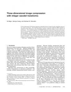
International Journal of Electrical and Electronics Research ISSN 2348-6988 (online) Vol. 3, Issue 1, pp: (156-164), Month: January - March 2015, Available at: www.researchpublish.com 2.1 Block Processing: The input image is first resized (in 256 rows and 256 columns) and then padded if required. In this technique of image reduction process, the block processing is done prior to discrete cosine transform is applied to 8x8 pixel blocks of image and then padded them if required. Hence if the input image is 256x256 pixels in size, we break it into 32 square blocks of size 8x8 and treat each block independently as shown in given below figure 1.
(a)
(b) Figure 2: (a) Input image, (b) image obtained after block processing operation
2.2 Discrete Cosine Transform: Transform Coding: In transform coding, a block of correlated pixels is transformed into a set of less correlated coefficients. The transform to be used for data compression should satisfy two objectives. Firstly, it should provide energy compaction: i.e. the energy in the transform coefficients should be concentrated to as few coefficients as possible. This is referred to as the energy compaction property of the transform. Secondly, it should minimize the statistical correlation between the transform coefficients. As consequence transform coding has a good capability of data compression, because not all transform coefficients need to be transmitted in order to obtain good image quality and even those that are transmitted need not be represented with full accuracy in order to obtain good image quality. In addition the transform domain coefficients are generally related to the spatial frequencies in the image and hence the compression techniques can exploit the psychovisual properties of the HVS, by quantizing the higher frequency coefficients more coarsely, as the HVS is more sensitive to the lower frequency coefficients [2]. The Discrete Cosine Transform: The discrete cosine transform (DCT) represents an image as a sum of sinusoids of varying magnitudes and frequencies. In DCT for image, most of the visually significant information about the image is concentrated in just a few coefficients of the DCT[19]. For this reason, the DCT is often used in image compression applications. For example, the DCT is at the heart of the international standard lossy image compression algorithm known as JPEG. The important feature of the DCT is that it takes correlated input data and concentrates its energy in just the first few transform coefficients. If the input data consists of correlated quantities, then most of the n transform coefficients produced by the DCT are zeros or small numbers, and only a few are large (normally the first ones). The early coefficients contain the important (low-frequency) image information and the later coefficients contain the less-important (highfrequency) image information[2]. Compressing data with the DCT is therefore done by quantizing the coefficients. The small ones are quantized coarsely (possibly all the way to zero), and the large ones can be quantized finely to the nearest
Page | 158 Research Publish Journals
International Journal of Electrical and Electronics Research ISSN 2348-6988 (online) Vol. 3, Issue 1, pp: (156-164), Month: January - March 2015, Available at: www.researchpublish.com integer. After quantization, the coefficients (or variable-size codes assigned to the coefficients) are written on the compressed stream. Decompression is done by performing the inverse DCT on the quantized coefficients. This results in data items that are not identical to the original ones but are not much different. The DCT is applied to small parts (data blocks) of the image. It is computed by applying the DCT in one dimension to each row of a data block, then to each column of the result [19]. Because of the special way the DCT in two dimensions is computed, we say that it is separable in the two dimensions. Because it is applied to blocks of an image, we term it a “blocked transform”. The discrete cosine transform (DCT) helps separate the image into parts (or spectral sub-bands) of differing importance (with respect to the image's visual quality).
Figure 3: Discrete Cosine Transform
DCT Encoding: The general equation for a 1D (N data items) DCT is defined by the following equation: ( )
( ) ∑
()
*
(
)+ ( )
(1)
And the corresponding inverse 1D DCT transform is simple F-1(u), i.e.: Where ( )
{√
The general equation for a 2D (N by M image) DCT is defined by the following equation: (
)
( ) ( ) ∑
∑
() ()
*
(
)+
*
(
)+ ( ) (2)
And the corresponding inverse 2D DCT transform is simple F-1(u,v), i.e.: Where ( )
{√
The basic operation of the DCT is as follows: a)
The input image is 256 by 256.
b) f(i,j) is the intensity of the pixel in row i and column j. c)
F(u,v) is the DCT coefficient in row k1 and column k2 of the DCT matrix.
d) For most images, much of the signal energy lies at low frequencies; these appear in the upper left corner of the DCT. e) Compression is achieved since the lower right values represent higher frequencies, and are often small - small enough to be neglected with little visible distortion. f)
The DCT input is an 8 by 8 array of integers. This array contains each pixel's gray scale level.
g) 8 bit pixels have levels from 0 to 255. h) Therefore an 8 point DCT would be:
Page | 159 Research Publish Journals
International Journal of Electrical and Electronics Research ISSN 2348-6988 (online) Vol. 3, Issue 1, pp: (156-164), Month: January - March 2015, Available at: www.researchpublish.com Where, ( ) i)
{√
The output array of DCT coefficients contains integers; these can range from -1024 to 1023.
j) It is computationally easier to implement and more efficient to regard the DCT as a set of basis functions which given a known input array size (8 x 8) can be precomputed and stored. This involves simply computing values for a convolution mask (8 x8 window) that get applied (sum m values x pixel the window overlap with image apply window across all rows/columns of image). The values as simply calculated from the DCT formula. The 64 (8 x 8) DCT basis functions for input image are illustrated in given below figure.
Figure 4: DCT basis functions
Two Dimensional discrete cosine transform converts time domain to frequency domain. Another advantage of DCT is to reduce the blocking effect than the discrete fourier transform (DFT). The 64 pixel values in each block are transformed by the discrete cosine transform into a new set of 64 values. The proposed algorithm works on different coefficients (10, 15, 20, 30, 40, 50, 60, 61, 62, 63 and 64) values individually. These new 64 values, known also as the discrete cosine transform coefficients represent the spatial frequency of the image sub-block. The upper left corner of the DCT matrix has low frequency components. The top left coefficient is called the DC coefficient. Its value is proportional to the average value of the 8x8 pixels. The rest area called the AC coefficients. After applying the DCT2 to given image we obtained the given below image.
Figure 5: Two dimensional DCT coefficients of given image
Page | 160 Research Publish Journals
International Journal of Electrical and Electronics Research ISSN 2348-6988 (online) Vol. 3, Issue 1, pp: (156-164), Month: January - March 2015, Available at: www.researchpublish.com 2.3 Mean and Transpose of Matrix: We have calculated the mean of each 8x8 matrix for averaging and then taken transpose of mean matrix. 2.4 Vector and Sorting: We have transformed the transpose matrix into a vector so that I can applied the sorting process on a vector for selecting the coefficients. And by sorting we have arranged all the 64 coefficients in increasing order to make the selection of coefficients easy and arbitrary. 2.5 Zigzag Coding: The purpose of zigzag coding is that we gradually move from the low frequency to high frequency, avoiding abrupt jumps in the values. Zigzag coding will lead to long run of 0’s. Zigzag coding converts the two dimensional image array into one dimensional array. In other words we can say that it converts the 8x8 matrix into 1x8 matrix.
Figure 6: An example used in DCT-based coding scheme. (A) The corresponding subimage matrix (B) The quantized DCT coefficient matrix of (A). (C) The zig–zag scanning order. (D) The zig–zag scanned sequence of (B)
2.6 Huffman Coding and Decoding: The main aim of Huffman coding is to eliminate the coding redundancy. It is a form of statistical coding which attempts to reduce the amount of bits required to represent a string of symbols. And due to use of Huffman coding the use of optimal code word having minimum average length. And decoding is the reverse of coding. Decoding is done to get back the original. 2.7 Zigzag Decoding: The purpose of Zigzag decoding is the reconstruction of 8x8 block matrix from the linear sequence of data. In other words we can say that it converts the one dimensional array into two dimensional array. 2.8 Inverse Discrete Cosine Transform: Now the image recovery will be achieved through the two dimensional inverse discrete cosine transform as shown in signal flow diagram (in figure 1).
3.
DEVELOPMENT OF IMAGE COMPRESSION ALGORITHM
Step 1- Read the gray scale image on to the workspace of the MATLAB. Step 2- Resize the input image (256x256) Step 3- Divide the image in 32 blocks of size 8x8 Step 4- Now applying DCT2 to each block
Page | 161 Research Publish Journals
International Journal of Electrical and Electronics Research ISSN 2348-6988 (online) Vol. 3, Issue 1, pp: (156-164), Month: January - March 2015, Available at: www.researchpublish.com Step 5- Calculate mean for each 8x8 block Step 6- Take transpose of mean matrix Step 7- Now converting transpose matrix into vector Step 8- Applying sorting process Step 9- Now select the coefficients value Step 10- Apply Zigzag coding Step 11- Apply Huffman coding Step 12- Apply Huffman decoding Step 13- Apply inverse of Zigzag coding Step 14- Take IDCT2 Step 15- Then we performed image compression Step 16- After compression we obtained the CR and PSNR
4.
RESULTS AND DISCUSSION
As we know that compression are the necessary steps in digital imaging technology. In this research we have designed an algorithm for image compression. For image compression we are using two dimensional Discrete Cosine Transform (DCT2). The performance of image compression algorithm is measured in certain standard terms. These are compression ratio (CR) and peak signal to noise ratio (PSNR). Compression ratio (CR) is defined as the nominal bit depth of the original image in bits per pixel (bpp) divided by the bpp necessary to store the compressed image. In other words we can say that it is the ratio of the original (uncompressed) image to the compressed image is referred to as the compression ratio (CR). The PSNR computes the peak signal to noise ratio, in decibels, between two images. This ratio is often used as a quality measurement between the original and a compressed image. The higher the PSNR, the better the quality of the compressed or reconstructed image. For each compressed and reconstructed image, compression ratio (CR) and peak signal to noise ratio (PSNR) was calculated. The image compression results of medical image (shown in figure 7) for different values of coefficients.
Figure 7: Image Compression Results
Page | 162 Research Publish Journals
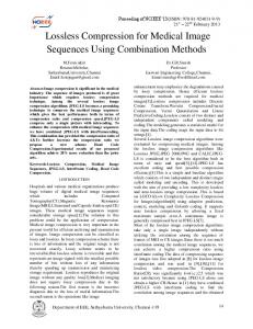
International Journal of Electrical and Electronics Research ISSN 2348-6988 (online) Vol. 3, Issue 1, pp: (156-164), Month: January - March 2015, Available at: www.researchpublish.com Initially, an arbitrary coefficient values were chosen. The proposed algorithm works on different coefficients (10, 15, 20, 30,40,50,60,61,62,63 and 64) values individually. After compression for each coefficient value we have calculated the CR and PSNR separately as shown in Table 1. Table 1: Compression Ratio and Peak Signal to Noise Ratio values
Number of Coefficient 10 15 20 30 40 50 60 61 62 63 64
CR(Compression Ratio) 31 28 26 23 21 20 20 20 20 20 20
PSNR (in dB) 27.7871 29.2713 30.7972 33.5804 36.6284 40.3664 45.4757 45.9764 46.4508 46.6301 46.6809
For 10 coefficients the CR is 31, for 40 coefficients it is 21 and for 64 CR is 20. So when we are increasing the number of coefficients the CR reduced (as shown in figure 4.2.). For 10 coefficient the PSNR value is 27.7871 dB, for 40 coefficient it is 36.6284 dB, and for 64 coefficient PSNR is 46.6809 dB . So when we are increasing the number of coefficients the PSNR is also increased (as shown in figure 8). Number of Coefficients v/s PSNR 50 45 40 35 30
Compression Ratio & 25 PSNR
CR PSNR
20 15 10 5 0 10
15
20
30
40
50
60
61
62
63
64
Number of Coefficients
. Figure 8: CR and PSNR curves
5.
CONCLUSION AND FUTURE WORK
Medical images are very important for diagnostics and therapy. However, digital imaging generates large amounts of data which need to be compressed, without loss of relevant information, to economize storage space and allow speedy transfer. In this research DCT2 technique is implemented for medical image compression, which provides high compression ratios with less loss of diagnostic quality. Proposed technique performs well in terms of compression ratio and reconstruction quality. As a result the storage requirement and transmission times are reduced. The proposed algorithm improves the quality of compressed images and it also reduces the block artifacts. Image compression is fundamental to the efficient and cost effective use of digital imaging technology and applications. Further we can improve the compressed image quality by using filtering techniques and also can improve the PSNR values for compressed image. There is a possibility of using region of interest (ROI) for image compression. And there is
Page | 163 Research Publish Journals
International Journal of Electrical and Electronics Research ISSN 2348-6988 (online) Vol. 3, Issue 1, pp: (156-164), Month: January - March 2015, Available at: www.researchpublish.com a scope of research for finding out better image compression segmentation methods for ROI selection on which medical community will trust.
REFERENCES [1]
R. C. Gonzalez, R. E. Woods, “Digital image processing,” Pearson Education, II Edition, 2003
[2]
David Salomon, “Data compression” spinger, Fourth Edition,2007
[3]
Jiankun Li, Jin Li, and C.-C. Jay Kuo, “Layered DCT Still Image Compression”, IEEE TRANSACTIONS ON CIRCUITS AND SYSTEMS FOR VIDEO TECHNOLOGY, VOL. 7, NO. 2, pp. 440-443,APRIL 1997
[4]
Zixiang Xiong, Kannan Ramchandran, Michael T. Orchard, and Ya-Qin Zhang,” A Comparative Study of DCTand Wavelet- Based Image Coding”, IEEE TRANSACTIONS ON CIRCUITS AND SYSTEMS FOR VIDEO TECHNOLOGY, VOL. 9, NO. 5, pp. 692- 695, AUGUST 1999
[5]
Panos Nasiopoulos and Rabab K. Ward, “A High-Quality Fixed- Length Compression Scheme for Color Images”, IEEE TRANSACTIONS ON COMMUNICATIONS, VOL. 43, NO. 11, pp. 2672-2677, NOVEMBER 1995
[6]
K. R. Rao and P. Yip, Discrete Cosine Transform. New York: Academic, 1990.
[7]
J. M. Shapiro, “Embedded image coding using zerotrees of wavelet coefficients,” IEEE Trans. Signal Processing, vol. 41, pp. 3445– 3463, Dec. 1993.
[8]
D.Wu and E.C.Tan,“Comparison of loss less image compression”. TENCON 99 proceedings of the IEEE region 10 conference, Cheju island, South korea, vol.1, 1999, pages 718-721
[9]
Cécile DELGORGE, Christophe ROSENBERGER, Pierre VIEYRES, Gérard POISSON “JPEG2000, an adapted compression method for ultrasound images? A comparative study”, http://www.bourges.univorleans.fr/otelo/publications-7-sc12002 delgorge.pdf, in August 2008.
[10]
Chaur-Chin Chen, "On the selection of image compression algorithms," 14th International conference on pattern recognition (ICPR'98) - Volume 2, 1998.
[11]
Amhamed saffor, Abdul Rahman Ramli, Kwan-Hoong Ng, “A Comparative study of Image Compression between JPEG and WAVELET”. Malaysian journal of computer science, vol. 14 no. 1, June 2001, Pages.39-45.
[12]
Eleftherios Kofidis1, Nicholas Kolokotronis, Aliki Vassilarakou, Sergios Theodoridis, Dionisis Cavouras” Wavelet-based medical image compression” Future generation computer systems , Volume 15 , Issue 2, March 1999 ,Pages 223–243
[13]
Bryan E. Usevitch” A Tutorial on modern lossy wavelet image compression: Foundations of JPEG 2000”IEEE signal processing magazine, Volume 18, Sept. 2001 Pages 22 -35 .
[14]
Yen-Yu Chen” Medical image compression using DCT-based subband decomposition and modified SPIHT data organization” International journal of medical informatics, 76,2 0 0 7,pages 717–725.
[15]
Amir Said” A New, fast, and efficient image codec based on set partitioning in hierarchical trees” IEEE transactions on circuits and systems for video technology, vol. 6, no. 3, June 1996, Pages243 – 250.
[16]
Stephen A. Martucci” A Zerotree wavelet video coder” IEEE transactions on circuits and systems for video technology, vol. 7, no. 1, February 1997 , Page:109 – 118.
[17]
Charles D. Creusere “A New method of robust image compression based on the embedded zerotree wavelet algorithm” IEEE transactions on image processing, Volume 6, no.10, Oct. 1997 , Pages 1436 - 1442
[18]
Pamela C. Cosman” Vector quantization of image subbands: A Survey” IEEE transactions on image processing, Volume 5, no. 2, Feb. 1996 Page(s):202 – 225.
[19]
Andrew B. Watson” Image compression using the Discrete Cosine Transform” Mathematica journal, 4(1), 1994, Pages 81-88
Page | 164 Research Publish Journals