emory Address (one dot per a ccess). Spatial. Locality. Temporal. Locality ..... XenSource was recently acquired by Citrix. â¢OpenVZ: An open source product ...
Advanced Computer Architecture
Memory Hierarchy Design
Dr. Shadrokh Samavi
Some slides are from the instructors‟ resources which accompany the 5th and previous editions. Some slides are from David Patterson, David Culler and Krste Asanovic of UC Berkeley; Israel Koren of UM Amherst, and Milos Prvulovic of Georgia Tech. Otherwise, the source of the slide is mentioned at the bottom of the page. Please send an email if a name is missing in the above list.
Dr. Shadrokh Samavi
INTRODUCTION
Dr. Shadrokh Samavi
3
Introduction • Programmers want unlimited amounts of memory with low latency • Fast memory technology is more expensive per bit than slower memory • Solution: organize memory system into a hierarchy
– Entire addressable memory space available in largest, slowest memory – Incrementally smaller and faster memories, each containing a subset of the memory below it, proceed in steps up toward the processor
• Temporal and spatial locality insures that nearly all references can be found in smaller memories
– Gives the allusion of a large, fast memory being presented to the processor
Dr. Shadrokh Samavi
4
Memory Hierarchy
Dr. Shadrokh Samavi
5
Performance
Processor-Memory Performance Gap: (grows 50% / year)
µProc 60%/year “Moore‟s Law”
DRAM
7%/year
Time Dr. Shadrokh Samavi
6
Memory Hierarchy Design • Memory hierarchy design becomes more crucial with recent multi-core processors:
– Aggregate peak bandwidth grows with # cores:
• Intel Core i7 can generate two references per core per clock • Four cores and 3.2 GHz clock – 25.6 billion 64-bit data references/second + – 12.8 billion 128-bit instruction references – = 409.6 GB/s!
• DRAM bandwidth is only 6% of this (25 GB/s) • Requires: – Multi-port, pipelined caches – Two levels of cache per core – Shared third-level cache on chip
Dr. Shadrokh Samavi
7
memory hierarchy in embedded computers Memory hierarchy of the embedded computers different than the desktops:
1- used in real-time applications, caches improve average case performance, but can degrade worst case performance. 2- Concerned about power and battery life, hardwareintensive memory hierarchy performance not interesting. 3- embedded systems only run one application. The protection role of the memory hierarchy is often diminished. 4- the main memory itself may be quite small and no disk storage.
Dr. Shadrokh Samavi
8
Review of the ABCs of Caches
Dr. Shadrokh Samavi
9
1) cache hit 2) cache miss 3) block 4) virtual memory 5) page 6) page fault 7) memory stall cycles 8) miss penalty 9) miss rate 10) address trace 11) direct mapped 12) fully associative 13) n-way set associative 14) valid bit 15) dirty bit 16) least-recently used 17) random replacement 18) block address 19) block offset 20) tag field 21) index 22) write through 23) write back 24) write allocate 25) no-write allocate 26) instruction cache 27) data cache 28) unified cache 29) write buffer 30) average memory access time 31) hit time 32) misses per instruction 33) write stall Dr. Shadrokh Samavi
10
Miss-oriented approach to memory access
Dr. Shadrokh Samavi
11
Example Assume we have a computer where the clocks per instruction (CPI) is 1.0 when all memory accesses hit in the cache. The only data accesses are loads and stores, and these total 50% of the instructions. If the miss penalty is 25 clock cycles and the miss rate is 2%, how much faster would the computer be if all instructions were cache hits? Ideal Cache
Real Cache Dr. Shadrokh Samavi
12
Typical levels in the hierarchy
Dr. Shadrokh Samavi
13
Four Memory Hierarchy Questions For the first level of the memory hierarchy: Q1: Where can a block be placed in the upper level? (Block placement)
Q2: How is a block found if it is in the upper level? (Block identification) Q3: Which block should be replaced on a miss? (Block replacement)
Q4: What happens on a write? (Write strategy) Dr. Shadrokh Samavi
14
Locality of Reference
Consider the string of references in a typical program
1. Temporal Locality 2. Spatial Locality 3. Sequential Locality
Dr. Shadrokh Samavi
15
Prefetch Policy 1. Prefetch on a miss. 2. Tagged prefetch.
BLOCK i
BLOCK i+1
BLOCK i+2
Dr. Shadrokh Samavi
16
Example: cache has 8 block frames and memory has 32 blocks. Dr. Shadrokh Samavi
17
Direct-Mapped Cache
Advantage: simple fast Disadvantage: conflict (thrashing)
Dr. Shadrokh Samavi
18
Direct-Mapped Cache Block address
31 Cache Tag
Example: 0x50
Stored as part of the cache “state”
Cache Data Byte 31
0x50
:
4 0 Byte Select Ex: 0x00
Byte 63
Byte 0
:
: Byte 1023
Dr. Shadrokh Samavi
0 Byte 33 Byte 32 1 2 3 Byte 1
:
Cache Tag
: :
Valid Bit
9 Cache Index Ex: 0x01
Byte 992
31
19
Fully Associative Mapping
Dr. Shadrokh Samavi
20
Fully Associative Mapping
Dr. Shadrokh Samavi
21
Set Associative Mapping
Valid
Cache Tag
:
: Adr Tag
Cache Index Cache Data Cache Data Cache Block 0 Cache Block 0
:
Compare
:
Sel1 1
Mux
0 Sel0
Cache Tag
:
Valid
:
Compare
OR Hit
Dr. Shadrokh Samavi
Cache Block
22
Disadvantage of Set Associative Cache • N-way Set Associative Cache versus Direct Mapped Cache: – N comparators vs. 1
– Extra MUX delay for the data – Data comes AFTER Hit/Miss decision and set selection • In a direct mapped cache, Cache Block is available BEFORE Hit/Miss:
– Possible to assume a hit and continue. Recover later if miss.
Dr. Shadrokh Samavi
23
Next and Last references K dt(x) forward distance for block x=
bt(x) backward distance for block x=
Dr. Shadrokh Samavi
K
24
Replacement Policies • Z(t) : existing set of blocks in cache. • Q(z): the block that is to be replaced.
1. LRU
Q(Z(t))=Y iff max{bt(x) } = y xZ
2. MIN
Q(Z(t))=Y iff max{dt(x) } = y xZ
3. LFU
4. FIFO
5. CLOCK 6. LIFO Dr. Shadrokh Samavi
7. RAND 25
Clock Replacement Policy Initial values in LRU table
0 0 0 0
0 0 0 0 0 0 0 0 0 0 0 0
0 0 0 0 0 0 0 0
0 0 0 0 0 0 0 0
0 0 0
0 0 0 0 0 0 0 0 0 0 0 0 0 0 0 0 0 0 0 0 0
Block 1 is referenced 1 1 1 1 1 1 1 0 0 0 0 0 0 0 0 0 0 0 0 0 0 0 0 0 0 0 0 0 0 0 0 0 0 0
0
0 0 0 0 0 0 0 0 0 0 0 0 0 0 0 0 0 0 0 0 0
The sequence of references are: 1,2,3,4,5,6,7,8,1 after that a replacement is to be made. Dr. Shadrokh Samavi
26
Clock Replacement Policy Block 2 is referenced
1
Block 3 is referenced 0 0 1 1 1 1 1
1 1 1 1 1 0 0 0 0 0 0 0 0 0 0 0 0 0 0 0 0 0 0 0 0 0
0 1 1 1 1 1 1 1 1 1 1 1 1 0 0 0 0 0 0 0 0 0 0 0 0 0 0
0 0 0 0 0 0 0 0 0 0 0 0 0 0 0 0 0 0 0 0 0
0 0 0 0 0 0 0 0 0 0 0 0 0 0 0 0 0 0 0 0 0
0 1 1
1
1
1
1
1
Dr. Shadrokh Samavi
1
27
Clock Replacement Policy Block 4 is referenced 0 0 0 1 1 1 1 0 0 1 1 1 1 1 0 1 1 1 1 1 1 1 1 1 1 1 1 1
1
0 0 0
0 0 0 0
0 0 0 0 0 0 0 0 0 0 0 0 0 0 0 0 0 0 0 0 0
Dr. Shadrokh Samavi
Block 5 is referenced 0 0 0 0 1 1 1
1
0 0 0 1 0 0 1 1 0 1 1 1
1 1 1
1 1 1
1
1
1
1
1
1
1
1
0 0 0 0 0 0 0 0 0 0 0 0 0 0
0 0 0 0 0 0 0
28
Clock Replacement Policy Block 6 is referenced
1 1 1 1
0 0 0 0 0 0 1 1 1 1 1 1
0 0 0 0 0 0 0 0
1
1
1 1 1
1 1 1
0 1
1
1 1 1 1 1 0 0 0 0 0 0 0 0 0 0 0 0 0 0 1
1
Dr. Shadrokh Samavi
Block 7 is referenced 0 0 0 0 0 0 1 0 0 0 0 0 1 1 0 0 0 0 1 1 1 0 0 0 1 1 1 1 0 0 1 1 1 1 1 1
1
1 1
1 1 0 1 1 1 1 1 0 0 0 0 0 0 0
1 1
29
Clock Replacement Policy Block 8 is referenced 0 0 0 0 0 0 0 0 0 0 0 0 0 1 0 0 0 0 0 1 1 0 0 0 0 1 1 1 0 0 0
Block 1 is referenced 1 1 1 1 1 1 1 0 0 0 0 0 0 0 0 0 0 1 0 0 0 0 1 1 0 0 0 1 1 1
0
1
1
1
1
1
1 1
1 1
1 1
0 0 1 0
0 1
1
1 1
1
1
1
1
1
1
1
0 0 0 0
0 1
1 1
1 1
1 1
0 0 1 0
0 1
1
1
1
1
1
The block with all 0‟s in its row is to be replaced: block 2 Dr. Shadrokh Samavi
30
Effect of different replacement policies
Data cache misses per 1000 instructions
Dr. Shadrokh Samavi
31
Cache Update Policies Write through (WT) – WTWA – WTNWA tc = cache cycle tm= memory cycle tB= block transfer time Wt = Write ratio
Dr. Shadrokh Samavi
Average time to complete a 1- WTWA: 2- WTNWA:
32
Cache Update Policies Write Back (TB) – Simple write back (SWB)
– Flagged write back (FWB) • Average reference time (SWB) = • Average reference time (FWB) =
Dr. Shadrokh Samavi
33
Pentium 4 family and its competition.
Features
Athlon 64 FX
Athlon 64
Pentium 4 "C"
Pentium 4 "E"
Pentium 4 EE
Athlon XP 3200+
Clock speed
2.2 - 2.4 GHz (soon)
2 -2.2 GHz
2.4-3.4 GHz
2.8 GHz 3.4 GHz
3.2-3.4 GHz
2.2 GHz
process technology (µm)
0.13 SOI Cu
0.13 SOI Cu
0.13 Cu
0.09 Cu
0.13 Cu
0.13 Cu
Transistors (million)
105.9
105.9
55
125
168
37.5
voltage
1.55V
1.550V
1.5-1.55V
1.3V - 1.5V
1.55V
1.65V
die size (mm²)
193
193
131
112
> 200
101
Pipeline length (integer/FP)
12/17
12/17
21
31
21
10/15
Dr. Shadrokh Samavi http://www.aceshardware.com/ .
34
Pentium 4 family and its competition Cache configuration
Athlon 64 FX
Athlo n 64
L1-cache (Data/Instr)
64/64 KB
L1-cache latency (load to use)
Pentium 4 "C"
Pentium 4 "E"
Pentium 4 EE
Athlon XP 3200+
64/64 8 KB/ 8KB 16 KB**
16 KB/ 8-16 KB**
8 KB/ 816 KB**
64/64 KB
3
3
2
2
2
3
L2-cache
1024 KB
1024 KB
512 KB
1024 KB
512 KB
512 KB
L2-cache Width
128 bit
128 bit
256 bit
256 bit
256 bit
64 bit
L2-cache Latency load to use (+L1-latency)
16
16
9-20
9-20***
9-20
11-20 (*)
L3-cache
-
-
-
-
2 MB
-
Dr. Shadrokh Samavi http://www.aceshardware.com/ .
35
Intel Core i7-965 XE & Core i7-920
http://www.sharkyextreme.com/hardware/cpu/article.php/3261_3782516__1 Dr. Shadrokh Samavi
36
CINEBENCH 9.5 CPU TEST
http://www.sharkyextreme.com/hardware/cpu/article.php/3261_3782516__7
Dr. Shadrokh Samavi
WinRAR 3.80 Bechmark
http://www.sharkyextreme.com/hardware/cpu/article.php/3261_3782516__7
Dr. Shadrokh Samavi
Miss per 1000 instructions
Size
Instruction cache Data cache
Unified cache
8 KB
8.16
44.0
63.0
16 KB
3.82
40.9
51.0
32 KB
1.36
38.4
43.3
64 KB
0.61
36.9
39.4
128 KB
0.30
35.3
36.2
256 KB
0.02
32.6
32.9
Dr. Shadrokh Samavi
39
Example: Harvard Architecture Proc Unified 32KB L1 Cache
16KB L1 I-Cache
Proc
16KB L1 D-Cache
Which is better? Assume 36% instructions are data transfers 74% accesses are instructions – hit time=1, miss time=100 – Note that data hit has 1 stall for unified cache (only one port)
Miss rate 16 KB Instruction= 3.82/1000=0.004 1.00 Miss rate 16 KB data= 40.9/1000=0.114 0.36 Miss rate 32 KB unified= 43.3/1000=0.0318 1.00+0.36 Dr. Shadrokh Samavi
40
Example: Harvard Architecture
Average Memory Access Time= AMAT AMATsplit =74%(1+0.004100)+26% (1+0.114 100) =4.24
AMATunified =74%(1+0.0318100)+26%(1+1+0.0318100)=4.44
Dr. Shadrokh Samavi
41
Improving Cache Performance
Average memory access time = Hit time + Miss rate × Miss penalty
How do you define miss penalty? Is it the full latency of the miss to memory, or is it just the “exposed” or non-overlapped latency when the processor must stall? Memory stall cycles Instruction Misses Instruction
=
×
Dr. Shadrokh Samavi
(Total miss latency - Overlapped miss latency)
42
Improving Cache Performance AMAT= hit time+ (miss rate × miss penalty)
1. Reducing the miss penalty: multilevel caches, critical word first, read miss before write miss, merging write buffers, victim caches; 2. Reducing the miss rate: larger block size, larger cache size, higher associativity, pseudo-associativity, and compiler optimizations; 3. Reducing the miss penalty or miss rate via parallelism: nonblocking caches, hardware prefetching, and compiler prefetching; 4. Reducing the time to hit in the cache: small and simple caches, avoiding address translation, and pipelined cache access. Dr. Shadrokh Samavi
43
Reducing Cache Miss Penalty
Dr. Shadrokh Samavi
44
First Miss Penalty Reduction Technique: Multi-Level Caches
Question regarding performance gap: Should we make the cache faster to keep pace with the speed of CPUs, or make the cache larger to overcome the widening gap between the CPU and main memory?
Local miss rate: the number of misses in a cache divided by the total number of memory accesses to this cache. For L1-cache it is equal to Miss rateL1 and for L2 cache it is Miss rateL2. Global miss rate: The number of misses in the cache divided by the total number of memory accesses generated by the CPU. For L1 cache is still just Miss rateL1 For L2 cache = Miss rateL1 Miss rateL2.
Dr. Shadrokh Samavi
45
1st Miss Penalty Reduction Technique: Multi-Level Caches EXAMPLE Suppose that in 1000 memory references there are 40 misses in the L1 cache and 20 misses in the L2 cache. What are the various miss rates? The miss rate (either local or global) for the L1 cache is 40/1000 or 4%. The local miss rate for the L2 cache is 20/40 or 50%. The global miss rate of the second-level cache is 20/1000 or 2%.
Dr. Shadrokh Samavi
46
Miss rates
Miss rates of 2nd level cache. L1 has two 64KB Global miss rate of L2 where L1 is 32-KB
Cache size (KB)
Dr. Shadrokh Samavi
47
Relative execution time by second-level cache size. The two bars are for different clock cycles for a L2 cache hit. The reference execution time of 1.00 is for an 8192-KB second-level cache with a one-clock-cycle latency on a second-level hit.
Dr. Shadrokh Samavi
48
Multilevel inclusion: L1 data is always present in L2. Inclusion is desirable because consistency between I/O and caches (or among caches in a multiprocessor) can be determined just by checking the second-level cache. If L2 cache is slightly bigger than the L1 cache then multilevel exclusion: L1 data is never found in L2 cache. Typically, with exclusion a cache miss in L1 results in a swap of blocks between L1 and L2 instead of a replacement of a L1 block with a L2 block.
Dr. Shadrokh Samavi
49
2nd Miss Penalty Reduction Technique: Critical Word First and Early Restart Critical word first: Request the missed word first from memory and send it to the CPU as soon as it arrives; let the CPU continue execution while filling the rest of the words in the block. Critical-word-first fetch is also called wrapped fetch and requested word first. Early restart: Fetch the words in normal order, but as soon as the requested word of the block arrives, send it to the CPU and let the CPU continue execution.
Dr. Shadrokh Samavi
50
3rd Miss Penalty Reduction Technique: Giving Priority to Read Misses over Writes
Dr. Shadrokh Samavi
51
4th Miss Penalty Reduction Technique: Merging Write Buffer Write address V
V
V
V
100
1 Mem[100]
0
0
0
108
1 Mem[108]
0
0
0
116
1 Mem[116]
0
0
0
124
1 Mem[124]
0
0
0
V
V
V
1 Mem[100]
1
Mem[108] 1
Mem[116] 1
0
0
0
0
0
0
0
0
0
0
0
0
Write address V 100
Dr. Shadrokh Samavi
Mem[124]
52
5th Miss Penalty Reduction Technique: Victim Caches
Placement of victim cache in the memory hierarchy. Although it reduces miss penalty, the victim cache is aimed at reducing the damage done by conflict misses. Jouppi [1990] : 4-entry victim cache reduces the miss penalty for 20% to 95% of conflict misses.
Dr. Shadrokh Samavi
53
Reducing Miss Rate
Dr. Shadrokh Samavi
54
Reducing Miss Rate Compulsory— Also called cold start misses or first reference misses.
(Misses in even an Infinite Cache)
Capacity— (Misses in Fully Associative Size X Cache)
Conflict— Also called collision misses or interference misses.
(Misses in N-way Associative, Size X Cache)
More recent, 4th “C”: Coherence - Misses caused by cache coherence.
Dr. Shadrokh Samavi
55
Cache size 4 KB 4 KB 4 KB 4 KB 8 KB 8 KB 8 KB 8 KB 16 KB 16 KB 16 KB 16 KB 32 KB 32 KB 32 KB 32 KB 64 KB 64 KB 64 KB 64 KB 128 KB 128 KB 128 KB 128 KB 256 KB 256 KB 256 KB 256 KB 512 KB 512 KB 512 KB 512 KB
Degree associative 1-way 2-way 4-way 8-way 1-way 2-way 4-way 8-way 1-way 2-way 4-way 8-way 1-way 2-way 4-way 8-way 1-way 2-way 4-way 8-way 1-way 2-way 4-way 8-way 1-way 2-way 4-way 8-way 1-way 2-way 4-way 8-way
Total miss rate 0.098 0.076 0.071 0.071 0.068 0.049 0.044 0.044 0.049 0.041 0.041 0.041 0.042 0.038 0.037 0.037 0.037 0.031 0.030 0.029 0.021 0.019 0.019 0.019 0.013 0.012 0.012 0.012 0.008 0.007 0.006 0.006
Dr. Shadrokh Samavi
Miss rate components (relative percent) (Sum = 100% of total miss rate)
Compulsory 0.0001 0.0001 0.0001 0.0001 0.0001 0.0001 0.0001 0.0001 0.0001 0.0001 0.0001 0.0001 0.0001 0.0001 0.0001 0.0001 0.0001 0.0001 0.0001 0.0001 0.0001 0.0001 0.0001 0.0001 0.0001 0.0001 0.0001 0.0001 0.0001 0.0001 0.0001 0.0001
0.1% 0.1% 0.1% 0.1% 0.1% 0.1% 0.1% 0.1% 0.1% 0.2% 0.2% 0.2% 0.2% 0.2% 0.2% 0.2% 0.2% 0.2% 0.2% 0.2% 0.3% 0.3% 0.3% 0.3% 0.5% 0.5% 0.5% 0.5% 0.8% 0.9% 1.1% 1.1%
Capacity 0.070 0.070 0.070 0.070 0.044 0.044 0.044 0.044 0.040 0.040 0.040 0.040 0.037 0.037 0.037 0.037 0.028 0.028 0.028 0.028 0.019 0.019 0.019 0.019 0.012 0.012 0.012 0.012 0.005 0.005 0.005 0.005
72% 93% 99% 100% 65% 90% 99% 100% 82% 98% 99% 100% 89% 99% 100% 100% 77% 91% 95% 97% 91% 100% 100% 100% 94% 99% 99% 99% 66% 71% 91% 95%
Conflict 0.027 0.005 0.001 0.000 0.024 0.005 0.000 0.000 0.009 0.001 0.000 0.000 0.005 0.000 0.000 0.000 0.008 0.003 0.001 0.001 0.002 0.000 0.000 0.000 0.001 0.000 0.000 0.000 0.003 0.002 0.000 0.000
28% 7% 1% 0% 35% 10% 1% 0% 17% 2% 0% 0% 11% 0% 0% 0% 23% 9% 4% 2% 8% 0% 0% 0% 6% 0% 0% 0% 33% 28% 8% 4%
56
Reducing Miss Rate 0.14
1-way
Miss Rate per Type
0.12
2-way
0.1
4-way
0.08
8-way
0.06
Capacity
0.04 0.02
Cache Size (KB)
128
64
32
16
8
4
2
1
0
Compulsory
3Cs Absolute Miss Rate (SPEC92) Dr. Shadrokh Samavi
57
Reducing Miss Rate miss rate 1-way associative cache size X = miss rate 2-way associative cache size X/2 0.14
1-way
Miss Rate per Type
0.12 2-way 0.1 4-way 0.08 8-way 0.06
Capacity
0.04 0.02
Cache Size (KB)
128
64
32
16
8
4
2
1
0
Compulsory
2:1 Cache Rule Dr. Shadrokh Samavi
58
Reducing Miss Rate 100% 80%
2-way 4-way 8-way
60% 40%
Capacity
20%
Cache Size (KB)
128
64
32
16
8
4
2
0%
1
Miss Rate per Type
1-way
Compulsory
3Cs Relative Miss Rate Dr. Shadrokh Samavi
59
Reducing Miss Rate: Larger Block Size
Cache size Block size
4K
16K
64K
256K
16
8.57%
3.94%
2.04%
1.09%
32
7.24%
2.87%
1.35%
0.70%
64
7.00%
2.64%
1.06%
0.51%
128
7.78%
2.77%
1.02%
0.49%
256
9.51%
3.29%
1.15%
0.49%
Dr. Shadrokh Samavi
60
Reducing Miss Rate: Larger Block Size Average memory access time versus block size Cache size Block size Miss penalty
1K
4K
16K
64K
256K
16
82
13.341
8.027
4.231
2.673
1.894
32
84
12.206
7.082
3.411
2.134
1.588
64
88
13.109
7.160
3.323
1.933
1.449
128
96
16.974
8.469
3.659
1.979
1.470
256
112
25.651 11.651
4.685
2.288
1.549
Assume 80 clock cycles of overhead and then delivers 8 bytes every cycle
Dr. Shadrokh Samavi
61
Reducing Miss Rate: Larger Block Size
25% 1K
20% M iss Rate
4K
15%
16K 10% 64K 5%
256K
256
128
64
32
16
0%
Block Size (byte s)
Dr. Shadrokh Samavi
62
0.08
0.06 0.04
0.02
128
64
32
16
8
4
2
0 1
Miss Rate
Reducing Miss Rate: Larger Caches
Cache Size (KB)
Dr. Shadrokh Samavi
63
Reducing Miss Rate: Higher Associativity Associativity
Cache size (KB)
One-way
Two-way
Four-way
Eight-way
4
3.44
3.25
3.22
3.28
8
2.69
2.58
2.55
2.62
16
2.23
2.40
2.46
2.53
32
2.06
2.30
2.37
2.45
64
1.92
2.14
2.18
2.25
128
1.52
1.84
1.92
2.00
256
1.32
1.66
1.74
1.82
512
1.20
1.55
1.59
1.66
FIGURE 5.19 Average memory access time using miss rates in Figure 5.14 for parameters in the example. Red means that this time is higher than the number to the left; that is, higher associativity increases average memory access time. Clock cycle time2-way = 1.36 × Clock cycle time1-way Clock cycle time4-way = 1.44 × Clock cycle time1-way Clock cycle time8-way = 1.52 × Clock cycle time1-way Average memory access time8-way = 1.52 + (0.006 × 25) = 1.66
Dr. Shadrokh Samavi
64
Reducing Miss Rate: Pseudo-Associative Caches • How to combine fast hit time of Direct Mapped and have the lower conflict misses of 2-way SA cache? • Divide cache: on a miss, check other half of cache to see if there, if so have a pseudo-hit (slow hit)
Hit Time Pseudo Hit Time
Miss Penalty
Time • Drawback: CPU pipeline is hard if hit takes 1 or 2 cycles – Better for caches not tied directly to processor (L2) – Used in MIPS R1000 L2 cache, similar in Ultra SPARC
Dr. Shadrokh Samavi
65
Reducing Miss Rate: Pseudo-Associative Caches EXAMPLE: If block not found in regular hit, then needs 2 extra CC. Then which one is better: DIRECT, 2-WAY, or PSEUDO? ANSWER:
Tavg. Acc.
Pseudo
=t
hit pseudo
+ Miss Rate
Miss Rate pseudo × Miss Penalty
t hit pseudo = t hit Alternate hit rate Tavg. Acc.
Pseudo
1-way
pseudo
Pseudo
pseudo
pseudo
= Miss Rate 2-way × Miss Penalty
+ Alternate hit rate =hit Rate
× Miss Penalty
2-way
pseudo
- hit rate
= t hit 1-way + (Miss Rate
1-way
1-way
× 2
1-way
- Miss Rate 2-way) × 2 +
Miss Rate 2-way ×Penalty
Dr. Shadrokh Samavi
1-way
66
Reducing Miss Rate: Way Prediction Idea • conflict miss rate is decreased with higher associativity • but hit time goes up due to: more complex circuits needed to select and mux the right set member
• hence organize the cache as n way set associative
but use a predictor to say which way to look in rather than the whole set hence hit times are the same as a simple direct mapped cache
Is it reasonable • Alpha 21264 uses it, MIPS uses it post R10K both used a way predicted 2-way set associative model 2 benefits: power and speed if prediction is correct fast hit and slow hit problem if prediction is incorrect
• very similar to the pseudo associative model operational Dr. Shadrokh Samavi
67
Reducing Miss Rate: Compiler Optimizations • McFarling [1989] reduced caches misses by 75% on 8KB direct mapped cache, 4 byte blocks in software • Instructions – Reorder procedures in memory so as to reduce conflict misses – Profiling to look at conflicts (using tools they developed)
• Data – Merging Arrays: improve spatial locality by single array of compound
elements vs. 2 arrays – Loop Interchange: change nesting of loops to access data in order stored in memory – Loop Fusion: Combine 2 independent loops that have same looping and some variables overlap – Blocking: Improve temporal locality by accessing “blocks” of data repeatedly vs. going down whole columns or rows
Dr. Shadrokh Samavi
68
Reducing Miss Rate: Compiler Optimizations Merging Arrays Example …
0,0
0,100
… … 5000,0
…
5000,100
Matrix is stored in row-major manner. The original code would skip through memory in strides of 100 words, while the revised version accesses all the words in one cache block before going to the next block.
Dr. Shadrokh Samavi
69
Reducing Miss Rate: Compiler Optimizations (loop fusion) /* Before */ for (i = 0; i < N; i = i+1) for (j = 0; j < N; j = j+1) a[i][j] = 1/b[i][j] * c[i][j]; for (i = 0; i < N; i = i+1) for (j = 0; j < N; j = j+1) d[i][j] = a[i][j] + c[i][j];
/* After */ for (i = 0; i < N; i = i+1) for (j = 0; j < N; j = j+1) { a[i][j] = 1/b[i][j] * c[i][j]; d[i][j] = a[i][j] + c[i][j];} Dr. Shadrokh Samavi
70
Reducing Miss Rate: Compiler Optimizations (Blocking)
Storing the arrays in row major order or in column major order does not solve the problem because both rows and columns are used in every iteration of the loop. Loop interchange efforts are not helpful either.
Dr. Shadrokh Samavi
71
Reducing Miss Rate:
Compiler Optimizations
(Blocking)
Sudhakar Yalamanchili, Georgia Institute of Technology
Dr. Shadrokh Samavi
72
Reducing Miss Rate:
Dr. Shadrokh Samavi
Compiler Optimizations
(Blocking)
73
Reducing Cache Miss Penalty or Miss Rate via Parallelism
Dr. Shadrokh Samavi
74
% of the average memory stall time
Nonblocking Caches
Benchmarks Dr. Shadrokh Samavi
75
Prefetch Hardware Prefetching of Instructions and Data
Compiler-Controlled Prefetching: An alternative to hardware prefetching is for the compiler to insert prefetch instructions to request the data before they are needed. Dr. Shadrokh Samavi
76
Access time (ns)
Reducing Hit Time: Small and Simple Caches
Cache size Dr. Shadrokh Samavi
77
Reducing Hit Time: Avoiding Address Translation
Dr. Shadrokh Samavi
78
Reducing Hit Time: Pipelined Cache Access This technique is simply to pipeline cache access so that the effective latency of a L1 cache hit can be multiple clock cycles, giving fast cycle time and slow hits. For example, the pipeline for the Pentium takes 1 clock cycle to access the instruction cache, for the Pentium Pro through Pentium III it takes 2 clocks, and for the Pentium 4 it takes four clocks. This split increases the number of pipeline stages, leading to greater penalty on mispredicted branches and more clock cycles between the issue of the load and the use of the data
Dr. Shadrokh Samavi
79
Reducing Hit Time: Trace cache
Instead of limiting the instructions in a static cache block to spatial locality, a trace cache finds a dynamic sequence of instructions including taken branches to load into a cache block.
Dr. Shadrokh Samavi
80
Data cache in the Alpha 21264 Block Block address offset 1 Tag Index
(512 blocks)
2
Valid Tag
3 (512 blocks)
CPU address Data Data in out
Data
=?
2
3
2:1 Mux =?
4
Victim buffer
Lower level memory
Dr. Shadrokh Samavi
81
Dr. Shadrokh Samavi
82
Memory Technology
Dr. Shadrokh Samavi
83
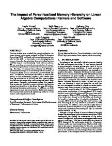
Memory Address (one dot per access)
Memory Reference Patterns
Temporal Locality
Spatial Locality Time
Donald J. Hatfield, Jeanette Gerald: Program Restructuring for Virtual Shadrokh Memory.Dr. IBM SystemsSamavi Journal 10(3): 168-192 (1971)
84
Core Memory • Core memory was first large scale reliable main memory – invented by Forrester in late 40s/early 50s at MIT for Whirlwind project
• Bits stored as magnetization polarity on small ferrite cores threaded onto 2 dimensional grid of wires • Coincident current pulses on X and Y wires would write cell and also sense original state (destructive reads) • Robust, non-volatile storage • Cores threaded onto wires by hand (25 billion a year at peak production) • Core access time ~ 1ms
Dr. Shadrokh Samavi
85
Semiconductor Memory, DRAM • Semiconductor memory began to be competitive in early 1970s – Intel formed to exploit market for semiconductor memory
• First commercial DRAM was Intel 1103 – 1Kbit of storage on single chip – charge on a capacitor used to hold value
• Semiconductor memory quickly replaced core in „70s
Dr. Shadrokh Samavi
86
One Transistor Dynamic RAM 1-T DRAM Cell word
TiN top electrode (VREF)
VREF
Ta2O5 dielectric
bit Storage capacitor (FET gate, trench, stack) poly word line
Dr. Shadrokh Samavi
W bottom electrode
87
DRAM Architecture bit lines
Col. 1
M
word lines Row 1
Row Address Decoder
N
N+M
Col. 2M
Row 2N
Column Decoder & Sense Amplifiers Data
Memory cell (one bit)
D
• Bits stored in 2-dimensional arrays on chip • Modern chips have around 4 logical banks on each chip
– each logical bank physically implemented as many smaller arrays
Dr. Shadrokh Samavi
88
DRAM Packaging Clock and control signals Address lines multiplexed row/column address
~7 ~12
DRAM chip
Data bus (4b,8b,16b,32b)
• DIMM (Dual Inline Memory Module) contains multiple chips with clock/control/address signals connected in parallel (sometimes need buffers to drive signals to all chips) • Data pins work together to return wide word (e.g., 64-bit data bus using 16x4-bit parts)
Dr. Shadrokh Samavi
89
DRAM Operation Three steps in read/write access to a given bank • Row access (RAS)
– decode row address, enable addressed row (often multiple Kb in row) – bitlines share charge with storage cell – small change in voltage detected by sense amplifiers which latch whole row of bits – sense amplifiers drive bitlines full rail to recharge storage cells
• Column access (CAS)
– decode column address to select small number of sense amplifier latches (4, 8, 16, or 32 bits depending on DRAM package) – on read, send latched bits out to chip pins – on write, change sense amplifier latches which then charge storage cells to required value – can perform multiple column accesses on same row without another row access (burst mode)
• Precharge
– charges bit lines to known value, required before next row access Each step has a latency of around 15-20ns in modern DRAMs Various DRAM standards (DDR, RDRAM) have different ways of encoding the signals for transmission to the DRAM, but all share same core architecture
Dr. Shadrokh Samavi
90
The performance of DRAMs is growing at a much slower rate compared to the processors. About 5% per year performance improvement in row access time, which is related to latency. The CAS or data transfer time, which is related to bandwidth, is growing at more than twice that rate.
Dr. Shadrokh Samavi
91
Improving bandwidth 1. Timing signals that allow repeated accesses to the row buffer without another row access time, typically called fast page mode. Such a buffer comes naturally, as each array will buffer 1024–2048 bits for each access. 2. Add a clock signal to the DRAM interface, so that the repeated transfers would not bear that overhead. Synchronous DRAM. SDRAMs typically also had a programmable register to hold the number of bytes requested, and hence can send many bytes over several cycles per request. 3. To transfer data on both the rising edge and falling edge of the DRAM clock signal, thereby doubling the peak data rate. This optimization is called double data rate (DDR). Dr. Shadrokh Samavi
92
Labeling DDR DIMM A DDR DIMM is connected to a 133 MHz bus. Why is it called PC2100? Its transfer rate is: 133 MHz × 2 × 8 bytes = 2100 MB/sec
Dr. Shadrokh Samavi
93
Labeling DDR DIMM Example Suppose a new DDR3 DIMM is transferring data at 16000 MB/sec. What should it be named? Answer The DIMM name should be PC16000. The clock rate of the DIMM: Clock lock rate × 2 × 8 = 16000 Clock rate = 16000⁄16 Clock rate = 1000 MHz.
PC2-8500 CL5 1066MHz DDR2 RAM
Dr. Shadrokh Samavi
94
Memory Dependability • Memory is susceptible to cosmic rays • Soft errors: dynamic errors
– Detected and fixed by error correcting codes (ECC)
• Hard errors: permanent errors
– Use sparse rows to replace defective rows
• Chipkill: a RAID-like error recovery technique
Dr. Shadrokh Samavi
95
Chipkill was introduced by IBM to solve the problem memory chip failure. Similar in nature to the RAID approach used for disks, Chipkill distributes the data and ECC information, so that the complete failure of a single memory chip can be handled by supporting the reconstruction of the missing data from the remaining memory chips. Using an analysis by IBM and assuming a 10,000 processor server with 4 GB per processor yields the following rates of unrecoverable errors in 3 years of operation:
1.
Parity only-about 90,000, or one unrecoverable (or undetected) failure every 17 minutes
2. ECC only-about 3500, or about one undetected or unrecoverable failure every 7.5 hours 3. Chipkill-6, or about one undetected or unrecoverable failure every 2 months
Dr. Shadrokh Samavi
96
Main Memory and Organizations for Improving Performance
Dr. Shadrokh Samavi
97
Main memory satisfies the demands of caches and serves as the I/O interface, as it is the destination of input as well as the source for output. Performance measures of main memory emphasize both latency and bandwidth. (Memory bandwidth is the number of bytes read or written per unit time.) -Latency concerns cache -Bandwidth concerns I/O and multiprocessors.
Dr. Shadrokh Samavi
98
Assume the performance of the basic memory organization is
• 4 clock cycles to send the address • 56 clock cycles for the access time per word
• 4 clock cycles to send a word of data cache block = four words, word =8 bytes, miss penalty =4 × (4 + 56 + 4) = 256 clk cycles memory bandwidth = 1/8 byte =(4×8/256) per clock cycle.
These values are our default case.
Dr. Shadrokh Samavi
99
Higher memory bandwidth
Dr. Shadrokh Samavi
100
Higher memory bandwidth First Technique for Higher Bandwidth: Wider Main Memory
With a main memory width of two words, the miss penalty in our example would drop from 4 ×64 or 256 clock cycles as calculated above to 2 × 64 or 128 clock cycles. There is cost of BUS CPUs will still access the cache a word at a time, so there now needs to be a multiplexer between the cache and the CPU.
Dr. Shadrokh Samavi
101
Higher memory bandwidth Simple Interleaved Memory
EXAMPLE: Block size = 1 word , Memory bus width = 1 word, miss rate = 3%, Memory accesses per instruction = 1.2 Cache miss penalty = 64 cycles Average CPI (ignoring cache misses) = 2 Block size= 2 words miss rate 2% Block size= 4 words miss rate 1.2%. Which one better: interleaving 2-way, 4-way, or doubling the width of memory and the bus? (access times: 4, 56, 4)
Dr. Shadrokh Samavi
102
Higher memory bandwidth
ANSWER 1-word blocks : CPI= 2 + (1.2 × 3% × 64) = 4.30 2-word blocks: 64-bit bus, no interleaving, CPI = 2 + (1.2 × 2% × 2 × 64) = 5.07 64-bit bus, interleaving, CPI = 2 + (1.2 × 2% × (4 + 56 + 8)) = 3.63 128-bit bus, no interleaving, CPI = 2 + (1.2 × 2% × 1 × 64) = 3.54 4-word blocks: 64-bit bus, no interleaving, CPI = 2 + (1.2 × 1.2% × 4 × 64) = 5.69 64-bit bus, interleaving, CPI = 2 + (1.2 × 1.2% × (4 + 56 + 16)) = 3.09 128-bit bus, no interleaving, CPI = 2 + (1.2 × 1.2% × 2 × 64) = 3.84 64-bit words
Dr. Shadrokh Samavi
103
Higher memory bandwidth Third Technique for Higher Bandwidth: Independent Memory Banks A generalization of interleaving is to allow multiple independent accesses, where multiple memory controllers allow banks (or sets of word-interleaved banks) to operate independently. Each bank needs separate address lines and possibly a separate data bus. For example, an input device may use one controller and one bank, the cache read may use another, and a cache write may use a third. Dr. Shadrokh Samavi
104
Virtual Memory
Dr. Shadrokh Samavi
105
Virtual Memory Running multiple processes, each has its own address space. Virtual memory, divides physical memory into blocks and allocates them to different processes. Protection restricts a process to its blocks. Before VM: If a program became too large for physical memory, programmer divided it into pieces, then identified the pieces that were mutually exclusive, and loaded or unloaded these overlays under user program.
Dr. Shadrokh Samavi
106
Virtual Memory The logical program in its contiguous virtual address space is shown on the left. It consists of four pages A, B, C, and D. The actual location of three of the blocks is in physical main memory and the other is located on the disk.
Dr. Shadrokh Samavi
107
Caches vs. virtual memory •Replacement on cache misses is primarily controlled by hardware, while virtual memory replacement is primarily controlled by OS. The longer miss penalty means it‟s more important to make a good decision, so the OS can be involved and take time deciding what to replace. •The size of the processor address determines the size of virtual memory, but the cache size is independent of the processor address size. •In addition to acting as the lower-level backing store for main memory in the hierarchy, secondary storage is also used for the file system. In fact, the file system occupies most of secondary storage. It is not normally in the address space. Dr. Shadrokh Samavi
108
Typical ranges of parameters
Dr. Shadrokh Samavi
109
Example of how paging and segmentation divide a program.
Dr. Shadrokh Samavi
110
Paging versus segmentation.
Dr. Shadrokh Samavi
111
4Q’s for virtual memory
Q1: Where can a block be placed in main memory? Q2: How is a block found if it is in main memory? Q3: Which block should be replaced on a virtual memory miss? Q4: What happens on a write?
Dr. Shadrokh Samavi
112
Q1: Where can a block be placed in main memory? The miss penalty for virtual memory involves access to a rotating magnetic storage device and is therefore quite high. Given the choice of lower miss rates or a simpler placement algorithm, operating systems designers normally pick lower miss rates because of the exorbitant miss penalty. Thus, operating systems allow blocks to be placed anywhere in main memory. According to the cache terminology this strategy would be labeled fully associative.
Dr. Shadrokh Samavi
113
Q2: How is a block found if it is in main memory?
Given a 32-bit virtual address, 4-KB pages, and 4 bytes per page table entry, the size of the page table would be (232/212) × 22 = 222 or 4 MB. Dr. Shadrokh Samavi
114
Q3: Which block should be replaced on a virtual memory miss? almost all operating systems try to replace the leastrecently used (LRU) block. Q4: What happens on a write? The level below main memory contains rotating magnetic disks that take millions of clock cycles to access. Thus, the write strategy is always write back.
Dr. Shadrokh Samavi
115
Techniques for Fast Address Translation
Dr. Shadrokh Samavi
116
Selecting a Page Size •The size of the page table is inversely proportional to the page size; memory (or other resources used for the memory map) can therefore be saved by making the pages bigger. •A larger page size can allow larger caches with fast cache hit times. •Transferring larger pages to or from secondary storage, possibly over a network, is more efficient than transferring smaller pages. •The number of TLB entries are restricted, so a larger page size means that more memory can be mapped efficiently, thereby reducing the number of TLB misses.
Dr. Shadrokh Samavi
117
A Typical Memory Hierarchy Split instruction & data primary caches (on-chip SRAM)
CPU RF
L1 Instruction Cache L1 Data Cache
Multiported register file (part of CPU)
Dr. Shadrokh Samavi
Multiple interleaved memory banks (off-chip DRAM) Memory
Unified L2 Cache
Memory Memory Memory
Large unified secondary cache (on-chip SRAM)
118
AMD Opteron caches and TLBs.
Dr. Shadrokh Samavi
119
Protection via Virtual Memory
Dr. Shadrokh Samavi
120
Protecting Processes
The simplest protection mechanism is a pair of registers that checks every address to be sure that it falls between the two limits, traditionally called base and bound. An address is valid if Base
≤
Address
≤
Dr. Shadrokh Samavi
Bound
121
Protecting Processes The computer designer has to help the operating system designer protect processes from each other by: 1. Provide at least two modes, indicating whether the running process is a user process or an operating system process ( called a kernel process, a supervisor process, or an executive process). 2. Provide a portion of the CPU state that a user process can use but not write. Including the base/bound registers, a user/supervisor mode bit(s), and the exception enable/disable bit. 3. Provide mechanisms whereby the CPU can go from user mode to supervisor mode and vice versa. The first direction is typically accomplished by a system call, implemented as a special instruction. The return to user mode is like a subroutine return that restores the previous user/supervisor mode. Dr. Shadrokh Samavi
122
Protection via Virtual Machines The idea of virtual machine is old but with the popularity of multiprocessors it is gaining more attention because: the increasing importance of isolation and security in modern systems, the failures in security and reliability of standard operating systems, the sharing of a single computer among many unrelated users, and the dramatic increases in raw speed of processors, which makes the overhead of VMs more acceptable.
Dr. Shadrokh Samavi
123
Protection via Virtual Machines A single computer runs multiple VMs and can support a number of different operating systems (OSes). A virtual machine monitor (VMM) or hypervisor is the heart of Virtual Machine and supports VMs. Hardware platform is “host”. Resources are shared by “guest” VMs. A physical resource may be time-shared, partitioned, or even emulated in software.
Dr. Shadrokh Samavi
124
x86 CPU hardware actually provides four protection rings: 0, 1, 2, and 3. Only rings 0 (Kernel) and 3 (User) are typically used. Dr. Shadrokh Samavi
125
Kernel-User 1.Kernel Mode In Kernel mode, the executing code has complete and unrestricted access to the underlying hardware. It can execute any CPU instruction and reference any memory address. Kernel mode is generally reserved for the lowest-level, most trusted functions of the operating system. Crashes in kernel mode are catastrophic; they will halt the entire PC. 2. User Mode In User mode, the executing code has no ability to directly access hardware or reference memory. Code running in user mode must delegate to system APIs to access hardware or memory. Due to the protection afforded by this sort of isolation, crashes in user mode are always recoverable. Most of the code running on your computer will execute in user mode.
Dr. Shadrokh Samavi
126
Hypervisor mode Under hypervisor virtualization a program known as a hypervisor (also known as a type 1 Virtual Machine Monitor or VMM) runs directly on the hardware of the host system in ring 0. The task of this hypervisor is to handle resource and memory allocation for the virtual machines in addition to providing interfaces for higher level administration and monitoring tools.
Dr. Shadrokh Samavi
127
Para-virtualization
Under Paravirtualization the kernel of the guest operating system is modified specifically to run on the hypervisor. This typically involves replacing any privileged operations that will only run in ring 0 of the CPU with calls to the hypervisor (known as hypercalls). The hypervisor in turn performs the task on behalf of the guest kernel.
Dr. Shadrokh Samavi
128
Full Virtualization
Full virtualization provides support for unmodified guest operating systems. The term unmodified refers to operating system kernels which have not been altered to run on a hypervisor and therefore still execute privileged operations as though running in ring 0 of the CPU.
Dr. Shadrokh Samavi
129
VMs also provide: 1. Managing software: VMs provide an abstraction that can run the complete software stack, even including old operating systems like DOS. A typical deployment might be some VMs running legacy OSes, many running the current stable OS release, and a few testing the next OS release. 2. Managing hardware: One reason for multiple servers is to have each application running with the compatible version of the operating system on separate computers, as this separation can improve dependability. VMs allow these separate software stacks to run independently yet share hardware, thereby consolidating the number of servers. Another example is that some VMMs support migration of a running VM to a different computer, either to balance load or to evacuate from failing hardware.
Dr. Shadrokh Samavi
130
Requirements of a Virtual Machine Monitor
VMM presents a software interface to guest software. It must isolate the state of guests from each other, and it must protect itself from guest software (including guest OSes). To “virtualize” the processor, the VMM must control access to privileged state, address translation, I/O, exceptions and interrupts.
VMM, just like paged virtual memory, must have: ■ At least two processor modes, system and user. ■ A privileged subset of instructions that is available only in system mode, resulting in a trap if executed in user mode. All system resources must be controllable only via these instructions.
Dr. Shadrokh Samavi
131
guest OS VMM
virtual memory real memory
physical memory
In principle, the guest OS maps virtual memory to real memory via its page tables, and the VMM page tables map the guests‟ real memory to physical memory. Rather than pay an extra level of indirection on every memory access, the VMM maintains a shadow page table that maps directly from the guest virtual address space to the physical address space of the hardware. Dr. Shadrokh Samavi
132
Virtualization Products •VMware: The major software of the field. Provides hardware emulation virtualization products called VMware Server and ESX Server. •Xen: A new open source contender. Provides a paravirtualization solution. Xen comes bundled with most Linux distributions. •XenSource: The commercial sponsor of Xen. Provides products that are commercial extensions of Xen focused on Windows virtualization. XenSource was recently acquired by Citrix. •OpenVZ: An open source product providing operating system virtualization. Available for both Windows and Linux. •SWsoft: The commercial sponsor of OpenVZ. Provides commercial version of OpenVZ called Virtuozzo. •OpenSolaris: The open source version of Sun‟s Solaris operating system provides operating system virtualization.
Dr. Shadrokh Samavi
133
Performance relative to native Linux
An Example VMM: The Xen Virtual Machine
Dr. Shadrokh Samavi
134
Receive throughput (Mbits/sec)
An Example VMM: The Xen Virtual Machine
Number of network interface cards
Dr. Shadrokh Samavi
135
An Example VMM: The Xen Virtual Machine
Dr. Shadrokh Samavi
136