Oct 8, 2015 - B. N. Katz,1,* M. P. Blencowe,1 and K. C. Schwab2,3. 1Department of ... +j. I. INTRODUCTION. During the past decade there has been a growing effort to ...... [16] D. K. Atwood, M. A. Horne, C. G. Shull, and J. Arthur, Phys. Rev.
PHYSICAL REVIEW A 92, 042104 (2015)
Mesoscopic mechanical resonators as quantum noninertial reference frames B. N. Katz,1,* M. P. Blencowe,1 and K. C. Schwab2,3 1
Department of Physics and Astronomy, Dartmouth College, Hanover, New Hampshire 03755, USA 2 Applied Physics, California Institute of Technology, Pasadena, California 91125, USA 3 Kavli Nanoscience Institute, Pasadena, California 91125, USA (Received 30 September 2014; published 8 October 2015)
An atom attached to a micrometer-scale wire that is vibrating at a frequency ∼100 MHz and with displacement amplitude ∼1 nm experiences an acceleration magnitude ∼109 m s−2 , approaching the surface gravity of a neutron star. As one application of such extreme noninertial forces in a mesoscopic setting, we consider a model two-path atom interferometer with one path consisting of the 100 MHz vibrating wire atom guide. The vibrating wire guide serves as a noninertial reference frame and induces an in principle measurable phase shift in the wave function of an atom traversing the wire frame. We furthermore consider the effect on the two-path atom wave interference when the vibrating wire is modeled as a quantum object, hence functioning as a quantum noninertial reference frame. We outline a possible realization of the vibrating wire, atom interferometer using a superfluid helium quantum interference setup. DOI: 10.1103/PhysRevA.92.042104
PACS number(s): 03.65.Ta, 03.30.+p, 42.50.Wk, 85.85.+j
I. INTRODUCTION
During the past decade there has been a growing effort to demonstrate nano-to-mesoscale mechanical systems existing in manifest quantum states [1–5]. One motivation is to understand how classical dynamics arises from quantum dynamics for systems with center of mass much larger than that of a single atom, and in particular establish whether the quantumto-classical transition is solely a consequence of environmentally induced decoherence [6] or perhaps ultimately due to some as yet undiscovered, fundamental “collapse” mechanism [7]. Three important milestones have been the demonstration of a ∼5 GHz mechanical resonator mode in a single-phonon Fock state [8], the demonstration of an entangled ∼10 MHz mechanical resonator mode–microwave cavity mode state [9], and the demonstration of a ∼4 MHz mechanical resonator in a quadrature-squeezed state with minimum variance 0.80 times that of the quantum ground state [10]. A particularly straightforward mechanical geometry is that of a long, thin suspended beam (wire) that is supported at both ends (i.e., doubly clamped). The wire can be driven transversely, exciting its fundamental flexural mode resonance, using several available actuation methods. For the example of a crystalline silicon (Si) wire that is a few micrometers long and a fraction of a micrometer in cross section, the mechanical fundamental flexural frequency is � ∼ 2π × 100 MHz [11]. Consider an Si atom or other atom type attached to the surface midway along the length of such a vibrating wire. Suppose that the midpoint displacement amplitude is X0 ∼ 1 nm. Then assuming that the midpoint undergoes simple harmonic motion, X(t) = X0 cos (�t + ϕ0 ), we have for the maximum acceleration experienced by the attached atom X¨ max = �2 X0 ∼ 109 m s−2 . This is an unexpectedly large acceleration, 108 times larger than the gravitational acceleration g on the surface of the Earth and closer in magnitude to the surface gravity of a neutron star [12].
*
Present address: Department of Physics, Pennsylvania State University, University Park, Pennsylvania 16802, USA. 1050-2947/2015/92(4)/042104(8)
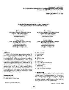
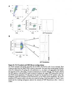
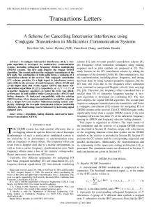
In this paper, we analyze one possible application of these extreme accelerations in a mesoscopic setting; there are undoubtedly other hitherto unexplored applications. In particular, we shall consider a model two-path atom interferometer shown schematically in Fig. 1. The right path consists of a vibrating wire, atom guide segment with micrometer dimensions similar to those described above. The left path is fixed, without a vibrating wire segment. Incident atom wave packets split into left and right wave packet components. The right wave component will accumulate a phase shift relative to the left wave component as a consequence of the vibrating wire functioning effectively as a noninertial reference frame for the traversing right wave. The right wave component eventually exits the noninertial frame and recombines with the left wave component. As we shall see below in Sec. II, this results in an in principle detectable fringe visibility for the left-right wave component interference as the vibrating wire amplitude is varied in the nanometer range. Quantum wave interference due to gravitational and inertial forces has been experimentally demonstrated for neutrons [13–16], atoms [17], Cooper pairs [18], and electrons [19], verifying the equivalence between these forces for quantum matter systems [20]. Furthermore, a recent comprehensive analysis takes into account also the possibility of atoms in each path of an interferometer experiencing different inertial forces, similar to our vibrating wire, interferometer model [21]. However, in all of these experiments and analyses the noninertial reference frames (and of course gravity) were treated as classical systems and there was no reason to view them otherwise. On the other hand, with mesoscopic mechanical resonators now being prepared and measured in manifest quantum states [8,9] as described above, it is very natural to consider the consequences for the matter wave interference of the vibrating wire functioning effectively as a quantum noninertial reference frame [22–26]. We shall therefore consider in Sec. III the effects on the fringe visibility for the left-right wave component interference when the vibrating wire is described quantum-mechanically; the details of the calculations are given in the Appendix. Section IV outlines a possible way to realize a noninertial, vibrating
042104-1
©2015 American Physical Society
B. N. KATZ, M. P. BLENCOWE, AND K. C. SCHWAB
PHYSICAL REVIEW A 92, 042104 (2015)
x and frame X coordinates, the Schr¨odinger equation for the atom in the vibrating frame described by the right path wave component ψR (x,t) is then i�
�2 ∂ 2 ψR ∂ψR =− ∂t 2m ∂x 2 1 + mω2 [x − X0 sin (π t/T ) cos (�t + ϕ0 )]2 ψR . 2 (1)
This equation may be straightforwardly solved assuming a Gaussian function form. With the atom entering the frame initially in its transverse ground state, ψR (x,0) = 2 )1/4 exp(− mωx ), the resulting interference between the left ( mω π� 2� and right path wave components at t = T is � mω − mωx 2 +iφ ∗ ψL (x,T )ψR (x,T ) = , (2) e � π� where the accumulated phase difference between the left and right waves is FIG. 1. Scheme of the two-path atom interferometer with noninertial, vibrating wire frame forming part of the right path.
wire-atom interferometer using a superfluid helium quantum interference setup. II. CLASSICAL FRAMES
Beginning first with a classical description, we approximate the noninertial frame as a long, thin beam (wire) of length L with hinged boundary conditions, so that for small-amplitude transverse displacements (X0 � L) the frame coordinates in the lowest, fundamental flexural mode are X(z,t) = X0 sin (π z/L) cos (�t + ϕ0 ), 0 � z � L. We suppose that atoms traversing the frame in the longitudinal, z-coordinate direction are described by localized wave packets propagating with uniform group velocity v = L/T relative to the vibrating frame, where T is the atom dwell time in the frame. The atoms are assumed to be confined by a harmonic potential to the frame in their transverse, x-coordinate direction that is aligned with the frame-flexing X-coordinate direction. The bound atom potential is then V (x,t) = 1 mω2 [x − X0 sin (π t/T ) cos (�t + ϕ0 )]2 , where both atom 2 and frame coordinates (x and X, respectively) are defined relative to a common origin in the assumed inertial laboratory frame. The various characteristic frequencies are assumed to satisfy π/T � � � ω, so that the atom spends many oscillation cycles in the frame, while it is tightly bound with negligible transverse motion relative to the frame. This assumption is not fundamental but rather for calculational convenience. In particular, assuming instead � � ω requires a more involved analysis of the interference between the left and right waves, but can still result in significant accumulated phase differences. Micrometer-scale resonators have masses M ∼ 10−15 kg, while the atom mass m ∼ 10−27 kg, i.e., M ≫ m. It is therefore reasonable to neglect the back action of the atom on the classical frame. We assume that the frame is initially excited in its fundamental transverse flexural mode and freely oscillates with negligible change in amplitude (i.e., damping) over the atom dwell time T . In terms of the transverse atom
m�2 X02 L m�2 X02 T ≡ . (3) 8� 8�v Note that the only atom attributes that the phase difference (3) depends on are its inertial mass m and traversal velocity v relative to the vibrating frame; ω does not appear to leading order as a consequence of the atom assumed to be tightly bound transversely to the frame, i.e., ω � �. Putting in some numbers: with m ∼ 10−27 kg, � ∼ 2π × 108 s−1 , and X0 ∼ 10−9 m, we have φ ∼ 0.5T (μsec). Thus, significant phase shifts result for dwell times in excess of a microsecond. Interestingly, this estimated phase shift following from Eq. (3) is of the same order of magnitude as the measured gravitational phase difference between two interfering neutron beam paths in Ref. [13], despite the fact that the vibrating wire acceleration magnitude �2 X0 is eight orders of magnitude larger than g ≈ 10 m s−2 . To understand this, consider the gravitational phase difference expression [20]: φ = mgα A/(�v), where m is the neutron mass, gα is the component of gravity in the plane of the neutron paths, A is the area enclosed by the two paths, and v is the neutron velocity. In contrast to this expression, Eq. (3) does not scale with the area enclosed by the two paths. This is because the transverse inertial force experienced by the atom is different in the two paths, in particular much larger in the right path containing the vibrating wire, whereas the gravitational field is uniform across the neutron interferometer. Comparing Eq. (3) with the gravitational phase difference expression, the reason for the similar phase shift magnitudes is that the effective area to atom velocity ratio term X0 L/v is about eight orders of magnitude smaller than the corresponding ratio A/v for the neutron interferometer. However, in contrast to the much larger ∼10 cm scale neutron interferometer where the acceleration due to gravity is of course well described classically, the micrometer scale, noninertial vibrating wire frame can also in principle be prepared in a manifest quantum state. A possibly more fundamental way to understand the phase difference (3) follows from the original observation of de Broglie [27] that the phase of a particle’s wave function can be directly expressed in terms of the proper time along the path
042104-2
φ≈
MESOSCOPIC MECHANICAL RESONATORS AS QUANTUM . . .
of the particle. In particular, we have [20,28] � �� t=T � t=T mc2 dτR − dτL , φ=− � t=0 t=0
(4)
where c is the speed of light in vacuum and τL(R) is the proper time elapsed for the atom traveling along the left (right) interferometer path. Since the frame velocity X˙ max = �X0 ∼ 1 m s−1 for the above considered � parameters, we have |vL(R) (t)| � c and hence dτL(R) = 1 − [vL(R) (t)/c]2 dt ≈ {1 − 1/2[vL(R) (t)/c]2 }dt, where vL(R) (t) is the left (right) path atom velocity relative the laboratory frame. Substituting in the approximation vR (t) ≈ −X0 � sin (π t/T ) sin (�t + ϕ0 ), valid for the condition π/T � � � ω, Eq. (4) then gives the same result as Eq. (3). Thus, the phase difference (3) can be viewed as a consequence of the “twin paradox” [20,28], where the right path wave packet bound to its noninertial, vibrating frame “ages” less than the left path wave packet during the elapsed laboratory coordinate time interval T . III. QUANTUM FRAMES
Moving on now to treating the vibrating frame as a quantum system, the Schr¨odinger equation for the composite atom-frame wave function �R (x,X,t) is i�
� 2 ∂ 2 �R ∂�R � 2 ∂ 2 �R 1 =− − + M�2 X2 �R ∂t 2m ∂x 2 2M ∂X2 2 1 + mω2 [x − X sin (π t/T )]2 �R , (5) 2
where we neglect the coupling between the frame and its dissipative environment and M is the effective motional mass of the frame in the fundamental flexural mode. The atom is assumed to enter the frame initially in its 2 transverse ground state: ψR (x,0) = ( mω )1/4 exp(− mωx ), with π� 2� �R (x,X,0) = ψR (x,0) R (X,0) for some initial prepared frame state R (X,0). A potential puzzle concerns the fact that, as a quantum object, the frame also has a phase and hence there may be an ambiguity concerning the part of the phase that “belongs” to the atom. This puzzle is resolved by noting that only the atoms are detected at the interferometer output, so that the frame state must be traced over in the interference term, which can be expressed as [cf. the classical frame interference Eq. (2)] (see Appendix)
PHYSICAL REVIEW A 92, 042104 (2015)
frame state √ ρˆframe (0) in terms of√a coherent state basis |α , where α = M�/(2�)X + iP / 2M��. Assuming Gaussian solutions and taking advantage of the separation of frequency scales, π/T � � � ω, we obtain (see Appendix for the details of the derivation) � 1 m i φˆ �e ≈ d 2 α�α|ρˆframe (0)|αeim�T /(4M) ei 8M (�−ω)T . (7) π Consider the example of a frame initially in a displaced coherent state: ρˆframe (0) = | R (0) � √R (0)| = √ |α0 �α0 |, where α0 = M�/(2�)X(0) + iP (0)/ 2M��, with X(0) = X0 cos ϕ0 and P (0) = −M�X0 sin ϕ0 . Equation (7) then gives �ei φ ≈ e|α0 | ˆ
m
m (ei 4M �T −1)+i 8M (�−ω)T
≈ ei 4M |α0 | m
= ei
2
m�2 X02 T 8�
m �T +i 8M (�−ω)T m +i 8M (�−ω)T
,
(8)
where the approximation in the second line assumes that m�T /(4M) � 1 and |α0 |2 [m�T /(4M)]2 � 1. These conditions put an upper limit on the magnitude of the atom dwell time T such that the back action of the atom on the frame is negligible. Equation (8) coincides with the classical frame accumulated phase difference (3), as we would expect for a coherent frame state. We now give two examples of manifest quantum frame states. As our first example, consider a frame initially in a Fock state: ρˆframe (0) = |N �N |, N = 0,1,2, . . . . Equation (7) then gives �ei φ ≈ ei 4M N�T +i 8M (�−ω)T . ˆ
m
m
(9)
Note that Eq. (9) can be obtained from Eq. (8) simply by replacing the frame coherent state amplitude modulus squared |α0 |2 with the frame Fock state number N . However, in contrast to the leading order accumulated phase difference for the coherent state and classical oscillating frame, the phase difference for the Fock state frame depends explicitly on the frame mass M. As our second quantum frame example, consider a frame initially in a quadrature squeezed vacuum state: ρˆframe (0) = ˆ )|0 �0|Sˆ † (ξ ), where the squeeze operator is de|ξ �ξ | = S(ξ ˆ ) = exp [ 1 (ξ ∗ aˆ 2 − ξ aˆ †2 )] [29]. Equation (7) then fined as S(ξ 2 gives m
ei 8M (�−ω)T ˆ �ei φ ≈ � m cosh2 (r) − ei 4M �T sinh2 (r)
† Trframe [�x|Uˆ R (T )|ψR (0) �ψL (0)| ⊗ ρˆframe (0)Uˆ L (T )|x ] � mω − mωx 2 i φˆ (6) = e � �e . π�
Here, we allow for the possibility that the frame is initially in a mixed state, while the unitary operators Uˆ L(R) (T ) implement the atom-frame evolution over the time interval T when the atom is either attached (R) or not attached (L) to the frame. Formally, we write the accumulated phase difference as an ˆ average, �ei φ , reflecting the fact that the frame is now in a quantum state. Equations (5) and (6) may be straightforwardly solved by transforming (5) to instantaneous normal mode coordinates such that (5) becomes separable, and decomposing the initial
2
m
ei 8M (�−ω)T ≈ � , m 1 − i 4M �T sinh2 (r)
(10)
where ξ = reiθ . Note that the interference term is suppressed for sufficiently large squeeze parameter r such that sinh2 (r) ≈ e2r /4 � 4M/(m�T ) � 1.
(11)
As our final example, we consider a frame initially in � −β��(N+1/2) a thermal state: ρˆframe (0) = Z −1 ∞ e |N �N |. N=0 In this case, Eq. (7) gives
042104-3
�ei φ ≈ e−i ˆ
mωT 8M
sinh(β��/2) . sinh [β��/2 − im�T /(8M)]
(12)
B. N. KATZ, M. P. BLENCOWE, AND K. C. SCHWAB
PHYSICAL REVIEW A 92, 042104 (2015)
Note that the interference is suppressed at sufficiently large temperatures such that (��β)−1 � 4M/(m�T ) � 1.
(13) IV. POSSIBLE REALIZATIONS
The interference suppression conditions (11) and (13) can be made more transparent by expressing in terms of the atom energy uncertainty arising from the corresponding frame energy uncertainty. For the example of the squeezed frame state, √ the frame√energy uncertainty is �Eframe = �� sinh(2r)/( 2) ≈ �� 2e2r /4 for r � 1, while for the thermal frame state, the frame energy uncertainty is �Eframe ≈ β −1 for β −1 � ��. Substituting into the respective conditions (11) and (13), we obtain the following common condition on the atom dwell time for the loss of quantum interference: T �
� m �Eframe M
≈
� , �Eatom
(14)
where we have neglected numerical factors. Thus, loss of interference occurs when the atom dwell time in the vibrating wire frame exceeds a dephasing time scale given by the atom’s energy uncertainty. We may speculate that Eq. (14) is a general condition for dephasing, together with the requirement that the initial frame state is such that the probabilities PN = �N|ρˆframe (0)|N are broadly distributed in the Fock state number N, as is the case for the squeezed state with r � 1 and thermal state with β −1 � ��. While a quantum frame state with a sufficiently large energy uncertainty can lead to a suppression of atom interference, so too can a mixed, classical frame state, as we have just seen for the squeezed vacuum and thermal state examples; it is not possible to qualitatively distinguish between quantum and classical frame states simply by measuring the atom wave interference for the two-path interferometer model that we are considering. Furthermore, while it is unlikely that we would be able to realize anytime soon such substantial squeezing [10] as required by (11) for interference suppression, mesoscale mechanical resonators viewed as quantum noninertial reference frames are nevertheless of theoretical interest for the unusual insights that are gained. Just as for the classical frame interference, it is interesting to determine whether the quantum frame interference follows from a more fundamental “twin paradox” description, where the proper time of the atom wave packet traversing the vibrating wire frame now develops a quantum uncertainty as a result of the frame being in a quantum state. Formally, the averaged interference term in (6) might be expressed as [cf. Eq. (4)]
T � mc2 ˆ �ei φ = T e−i � [ 0 dt(d τˆR /dt)−T ] ,
gravity at low energies [22], in particular the effect of quantum fluctuating space-time on matter wave interference [32,33].
We now outline possible methods for realizing the mesoscopic, vibrating wire interferometer. As was discussed, to realize a phase difference φ ∼ 1 with an atom and an acceleration of 108 g, one needs a wire frame dwell time of ∼1 μs. For a nanomechanical resonator with a length of approximately 1 μm, this requires an atom velocity of 1 m s−1 or less. Alternatively, electrons, given their much smaller mass, would require a dwell time approximately 1000 times longer [see Eq. (3)], and hence a velocity of