Introduction; The measurement of the four noise parameters ("s). NPs of a two-port in the microwave frequency range is usually performed by measuring the ...
it does not require measurement of the cold-source; (ii) T, need not be To;(iii) c,(i = 1, ..., N) need not be either the same as or equal to To.Moreover, it demonstrates an improved accuracy in critical measurement situations (i.e. lropTl in the two-port close to 1). Experimental verification is given up to 26GHz.
Method for measuring noise parameters of microwave two-port A. Lhzaro, L. Pradell and J.M. O'Callaghan A new tuner-based method for measuring the four noiseparameters of a two-port is proposed. It makes use of a novel measurement ratio that includes noise powers and mismatch factors simultaneously. In contrast to previous works, no restrictions on the noise source, tuner state temperatures and cold
temperatures are assumed.
Introduction; The measurement of the four noise parameters ("s) NPs of a two-port in the microwave frequency range is usually performed by measuring the two-port device noise figure F for a minimum of four source reflection-coefficients r,,produced with a tuner connected at the two-port input (reflection-type tuner) [I 61. The equation relating F and rs,( i = 1, ..., N)is expressed in linear form, and the resulting overdetermined linear equation system is solved for the NPs [I, 2, 51. A number of measurement methods have been proposed. In 131, F(rst) is determined from the measured r,, and the corresponding noise powers delivered by the two-port to the receiver, at room temperature. The system gain is computed from the hot and cold noise powers delivered by a two-state noise-source 13, 71.Equal hot and cold source reflection-coefficients = rs,) must be assumed. Typically, this assumption does not affect the measurement accuracy of the NPs, because the differences between r,, and rs, are very small, but some applications (for example, cryogenic measurements or radiometer calibration) may require different hot and cold loads. In 141, a method is given that avoids the former restriction by using an alternativemeasurement magnitude, i.e. the ratio between the delivered noise powers and a mismatch coeffcient. Only the hot-source measurement is required to determine the system gain, but it is implicitly assumed that the cold (room) temperature, T,, equals the reference temperature, To (= 290K) [4]. This assumption is a limitation in a real laboratory environment, or whenever the tuner includes semiconductor (PIN diode) switches, because the diodes add a non-thermal (shot) contribution to the temperatures of the tuner states, T,, ( i = 1, ..., N). Alternative techniques to measure the four N p s for the particular case of a transistor 181, make use of the transistor equivalent circuit as additional information. However, a tuner must be used to calibrate the receiver noise. ~
vsH
10,
,
120,
f,GHz ~
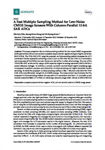
Fig. 2 HEMT noise parameters measured using new method, method proposed by Adamian 131, method proposed by Davidson [4] and F50 method [8] new method
~
0
v
Davidson Adamian
0 F50
Measurement method: To calibrate the receiver, the tuner is connected to its input and the noise power delivered to the receiver detector is measured for every tuner state r, ( i = 1, ..., N). This power can be expressed as: where k is the Boltzmann constant, r, is the receiver input reflection coefficient, Tst is the noise temperature of the source impedance r,,, TJr,) is its corresponding receiver noise temperature, (Cop) is the receiver transducer power gain, Go is the receiver transducer power gain for a matched source (r, = 0), and p(rR, r,) = ( l - ~ ~ s ~ z ) ~ l is- ~as ~mismatch R ~ z factor. Go is a constant throughout the measurement, because it only depends on receiver parameters. To eliminate the gain constant Go the noise power PH delivered by a hot source (whose hot temperature THis known), is used as a reference to define a novel measurement ratio R,:
The receiver noise temperature T, is expressed in a linear form by using the Lane's parameters A, B, C, D [I], whch are functions of the receiver NPs, T,,,,,, G,,, Bop,and R,,: 0.4I
I
200,
I
where Y, = Gs + jBs is the source admittance. Substituting eqn. 3 into eqn. 2, the following overdetermined linear equation system is obtained for A , B, C, D: [Sz]= [VI. [ A B 0
10
30
20
f,GHz
C D]'
(i = 1,..., N)
S, E R,TH - Ts,
(4)
(5)
(34611j
Fig. 1 Receiver noise parameters measured using new method, method proposed by Adamian [3] and method proposed by Davidson [4] ~
new method 0 Davidson V Adamian
While a tuner is required to measure the NPs of a general twoport andor to calibrate the receiver, a general case # Tsc, T, # To, T,, # To,and different T,, for every state i) is often encountered. No accuracy degradation should be expected in these cases if a measurement method with no restrictive assumptions were used. The purpose of this Letter is to propose a new method for measuring the four N P s of a two-port, based on a reflection-type tuner. It is a more general method than those in [3, 41 because: (i)
csH
1332
The system in eqn. 4 is solved for A, B, C, D, by weighted leastsquares using the concept of the pseudo-inverse matrix, and the receiver N P s are readily computed. This calculation completes the receiver calibration. Then the two-port is inserted, and by using the Friis's formula, the following equation is readily derived:
(i = ..., N) s; = TDUT(rSz) -R : T ~ ~ ~ (1,~ ~ ~(8))
ELECTRONICS LETTERS 25th June 1998
Vol. 34
No. 13
where R,‘is defined as in eqn. 2, but with the reflection coefficient r, referred to the two-port input. In eqn. 9, the reflection coefficients r,,’,rs/ correspond to rs,and r,,, respectively, but are and GavDuT are the two-port referred to the two-port output. TDUT noise temperature and available gain, respectively, and 72 is the receiver noise temperature, computed from the receiver N P s previously measured. The two-port noise temperature in eqn. 8 is expressed in linear form, and a linear system similar to eqns. 4 - 7 is obtained for [A B C DITDuT,with R,and S, replaced by R,‘and SE’,respectively.
Nonlinear stability anallysis of microwave circuits using commercial software A. Suarez, V. Iglesias, J.-M. Collantes, J. Jug0 and J.L. Garcia A new technique is presented for the stability analysis of steady nonlinear regimes in microwave circuits, using commercial software. The Nyquist stability criterion is applied to the openloop transfer functions of the circuit linearisation around the steady state. Through a simple nonlinear optimisationtechnique it is also possible to determine the predicted quasi-periodic or period-doubled steady solutions. The stability analysis of two varactor-based circuits has provided excellent results when compared with time domain simulations and measurements.
Experimental results: The method has been tested on on-wafer
transistors. The test setup includes a broadband (2-26GHz), commercial tuner [6] with nine available source states. The tuner and hot source reflection-coefficients are measured together with their corresponding noise powers and used in [2 - 91. Fig. 1 shows that the measured receiver NPs up to 26GHz for the method proposed here and for those proposed in [3, 41 are almost identical, which is to be expected since the test conditions needed in the former methods [3, 41 are met (TsX= r,, for [3] and T,, = To for [4]). Fig. 2 compares the measured N P s of an on-wafer HEMT up to 26GHz. The agreement between the four methods (Fs0method [SI is also compared) is good except at low frequencies, for which lroPTl is very high (close to 1). The new method is more robust to this critical measurement situation than those in [3, 41, which have nonphysical parameters. Conclusions; A novel tuner-based method for measuring the four NPs of a general two-port with no restrictions in the noise source or tuner, has been proposed and successfully applied to the receiver calibration and to an HEMT. It has been compared to other tuner-based methods in the literature, demonstrating accuracy improvements in the determination of the NPs for critical measurement situations, such as a device Ir& close to 1. Acknowledgment: This work has been supported by the research projects TIC93-672-C04-03 and TIC97-1129-C04-04 fmanced by the Spanish CICYT.
0 IEE 1998
7 May I998
Electronics Letters Online No: 19980942
A. Lazaro, L. Pradell and J.M. O’Callaghan (Polytechnic University of Catalunya (UPC), Dept. TSC, Campus Nord UPC, 08034 Barcelona, Spain)
References LANE, R.Q.:
‘The determination of device noise parameters’, Proc.
ZEEE, 1969, 57, pp. 1461-1462
and SANNINO, M.: ‘Computer-aided determination of microwave two-port noise parameters’, ZEEE Trans. Microw. Theory Tech., 1978, 26, (9), pp. 639-642 ADAMIAN, A., and UHLIR, A : ‘A novel procedure for receiver noise characterisation’, IEEE Trans. Znstrum. Meas., 1973, 22, (6), pp. 181-182 DAviDsoN, A.c., LEAKE, B.w., and STRID, E.: ‘Accuracy improvements in microwave noise parameter measurements’, IEEE Trans. Microw. Theory Tech., 1989, 37, (12), pp. 1973-1978 OCALLAGHAN, J.M., and MONDAL, J.P.: ‘A vector approach for noise parameter fitting and selection of source admittances’, ZEEE Trans. Microw. Theory Tech., 1991, 37, (12), pp. 1376-1382 NPTS-26 System, Cascade-Microtech, Inc., 14255 SW Brigadoon, Beaverton, OR 97005
CARUSO, G.,
CROZAT, P.]
DOUTLX,
c., C T I * ” ” E T ,
M
,
DANELON, V.) SYLVESTRE) a.,
and VERNET, G.: ‘SO 0 noise measurements with full receiver calibration without tuner’, Electron. Lett., 1996, 3, pp. 261-262 LAZARO, A., PRADELL, L., BELTRAN, A., and O’CALLAGHAN, J.M.: ‘Direct extraction of all four transistor noise parameters from Son noise figure measurements’, Electron. Lett., 1998, 32, (3), pp. 289291
ELECTRONICS LETTERS
25th June 7998 Vol. 34
Introduction: Harmonic balance (HB) commercial simulators are
an invaluable tool for the analysis of the nonlinear steady regimes of microwave circuits, such as power amplifiers, oscillators or frequency doublers. A nonlinear stability analysis is also necessary in order to ensure the physical existence of the simulated solulions [l, 21. This analysis provides information about the possible existence of unstable natural frequencies that would give rise to, often undesirable, quasi-periodic or period doubled regimes. However, the stability analysis of these regimes is not yet available. Instead, commercial simulators only include stability analysis options for the DC solutions of oscillator circuits. In this Letter, a new technique is presented for the stability analysis of nonlinear steady regimes, using commercial software. It is based on the Nyquist stability criterion, which is applied to the open-loop transfer function of the circuit linearisation around its nonlinear steady solution. To calculate this transfer function, a real frequency perturbation is introduced over the steady regime, in the form of an auxiliary generator (AG) of neghgible amplitude. This enables the evaluation of the open-loop transfer function at the AG location. The Nyquist plots are then directly obtained by sweeping the AG frequency. For a rigorous analysis, avoiding uncertainty about possible zero-pole cancellations, several observation ports should be considered sequentially. A new technique is also presented for the steady-state analysis of the predicted autonomous quasi-periodic and frequency divided regimes. This is based on nonlinear optimisation of the auxiliary generator variables, imposing a non-perturbation condition. The unstable natural frequency is estimated from the Nyquist plot, which provides a valuable starting point for the optimisation. Since the new analysis techniques are intended for commercial simulators, they are readily usable by any microwave-circuit designer. Advantage is also taken of the flexibility of commercial software, which enables the analysis of complex topologies, which are typically difficult to introduce in in-house software. Here, the proposed analysis method has been applied for the stability analysis of two varactor-based circuits: a simple circuit for frequency division and a frequency doubler that exhibits an asynchronousinstability. The respective period doubled and quasiperiodic solutions were predicted and determined by means of the new method, obtaining an excellent agreement with time domain simulations and measurements. For both the stability and steady state analysis, HP-MDS commercial software has been used.
Fig. 1 Block diagram of perturbed circuit, linearised around nonlinear periodic solution XpO
Analysis method: A nonlinear circuit, exhibiting a steady regime of f-d-entalf;,, will he considered To analyse its stability, a small
perturbation will be superimposed over the steady solution X,O. This is done by introducing into the circuit an auxiliary generator (AG) of negligible amplitude E and variable frequencyf,, with a filter which eliminates its influence at all frequencies different from its own [3]. The input immittance atf,, observed from the AG terminals, may be split into two contributions. Whenever possible,
No. 13
1333