The comparison between stereo camera depth resolution and perceived depth ... Section 6. 2. DEPTH RESOLUTION. 2.1 Human depth resolution. Binocular ...
Method for measuring stereo camera depth accuracy based on stereoscopic vision Mikko Kytö*, Mikko Nuutinen, Pirkko Oittinen Aalto University School of Science and Technology, Department of Media Technology, Otaniementie 17, Espoo, Finland ABSTRACT We present a method to evaluate stereo camera depth accuracy in human centered applications. It enables the comparison between stereo camera depth resolution and human depth resolution. Our method uses a multilevel test target which can be easily assembled and used in various studies. Binocular disparity enables humans to perceive relative depths accurately, making a multilevel test target applicable for evaluating the stereo camera depth accuracy when the accuracy requirements come from stereoscopic vision. The method for measuring stereo camera depth accuracy was validated with a stereo camera built of two SLRs (singlelens reflex). The depth resolution of the SLRs was better than normal stereo acuity at all measured distances ranging from 0.7 m to 5.8 m. The method was used to evaluate the accuracy of a lower quality stereo camera. Two parameters, focal length and baseline, were varied. Focal length had a larger effect on stereo camera's depth accuracy than baseline. The tests showed that normal stereo acuity was achieved only using a tele lens. However, a user's depth resolution in a video see-through system differs from direct naked eye viewing. The same test target was used to evaluate this by mixing the levels of the test target randomly and asking users to sort the levels according to their depth. The comparison between stereo camera depth resolution and perceived depth resolution was done by calculating maximum erroneous classification of levels. Keywords: Stereo camera, depth accuracy, depth resolution, stereo acuity, video see-through display
1. INTRODUCTION Evaluating stereo camera depth accuracy is a non-trivial task. Depth accuracy is affected by multiple error sources including calibration and matching errors of correspondence points. Stereo cameras have been used widely for measuring depth in photogrammetry and in remote sensing. In those areas the baselines (the distance between cameras) are very large and measures are taken mainly from static scenes. Human centered applications like augmented reality sets different accuracy requirements for stereo cameras. The stereo camera has short baseline and is usually wearable. Stereo cameras have to be fixed properly to prevent relative movements between the cameras and between the user and the cameras. Misalignment errors have to be traceable [1]. There is a need to examine the stereo camera’s accuracy in two ways (a) absolute depth measurement accuracy and (b) depth resolution. These properties should be investigated separately, so that characterization of a stereo camera and its error sources is possible. Standardized methods to evaluate the stereo camera depth accuracy don’t exist so far. Accuracy of a stereo camera is usually evaluated for example with human body [2] or objects like cars [3], so the dimensions of test 3D objects vary between studies. The aim of the study was to develop a method that could compare the measured and perceived depth resolution. The comparison between visual resolution and measured spatial resolution can be done with ISO 12233 resolution measurement standard for 2D images, but there doesn’t exist depth resolution standard for stereoscopic applications where the scene is measured and showed to user with same cameras. The method shown in this paper uses a modular test target which can be easily copied and used in various human centered applications in close range applications. For video see-through systems the human depth perception is usually investigated for absolute depths from the user (egocentric approach) (see [4] for reference) but the method presented in this study can also be used to measure human depth resolution. For example applications related to construction and assembly would need this kind of approach where the relations of depths of objects to each other are important. *mikko.kyto @tkk.fi; phone +358947023348; fax 1 222 555-876; http://media.tkk.fi/en/
Section 2 presents the basic concepts of human depth resolution and stereo camera depth resolution. The method for measuring stereo camera depth resolution in practice is presented in Section 3. The effect of two principal variables of stereo cameras, baseline and focal length, were tested with the developed method. The results of baseline tests were compared to subjective evaluations. The results of these tests are presented in Section 5. Conclusion of this study is in Section 6.
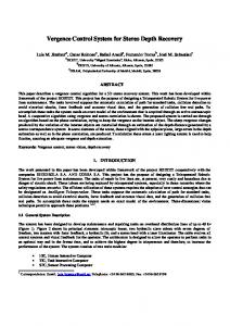
2. DEPTH RESOLUTION 2.1 Human depth resolution Binocular disparity has the biggest depth sensitivity (later called depth resolution) of depth cues when the distance is less than 5 meters [5] (see Figure 1.). This means that binocular disparity sets the requirement for system’s depth resolution. Of course the monocular depth cues have also important role in sensing the depths and should be noticed when defining the depth accuracy requirements. However, monocular depth cues depend on application specific issues so their influence on accuracy requirements should be evaluated in each separate case. dZh
Z
I
Figure 1. Depth resolution from binocular disparity dZh at distance Z. I is interpupillary distance, typically 6.5 cm.
Human depth resolution dZh from binocular disparity can be calculated with Equation 1 [6]: dZ h =
Z 2 ∆T I
(1)
where ∆T is the angular resolution of the human eye (stereo acuity), and for 80% of the population it’s below 30 arcsec (=0.008°)[7]. A widely used value is 20 arcsec [8]. Equation 1 applies to the depth difference of objects. So one cannot say that humans can judge a five meter absolute distance with a few centimeters accuracy. Instead, this depth difference between objects can be distinguished correctly. However the accuracy requirement from video see-through systems is different from direct naked eye viewing. In applications where the user operates based on stereo camera measurements it is not meaningful to measure the environment more accurately than humans can perceive. In stereoscopic video see-through systems the depth resolution [9] can be approximated with equation 2:
Z 2 ∆T (2) MNI where M is magnification (ratio of display FOV and camera FOV), N is the effective interpupillary distance (ratio of baseline and interpupillary distance). dZ st =
2.2 Stereo camera depth resolution Stereoscopic imaging geometry and quantization resolution set the limit for theoretical stereo camera depth resolution. The theoretical depth resolution of a stereo camera dZc at the distance Z is calculated as [10]: dZ c =
Z2 dp x fb
(3)
where f is focal length, b is baseline and dpx is disparity accuracy. The schematic concept of depth resolution is shown in Figure 2.
Depth resolution Depth resolution
f
a)
b
b)
Figure 2. The schematic representation of depth resolution with shorter baseline (a) and longer base (b).
The stereo camera depth estimates are however affected by alignment and calibration errors of stereo camera parameters [1]. Disparity accuracy depends on the matching accuracy of the correspondence algorithm. For these reasons the equation 2 is not enough for evaluating the depth resolution of practical stereo camera measurement systems as we will see in the experimental part of this study. 2.3 Theoretical comparison between camera and human In human centered applications for example in augmented reality the surrounding environment can be measured with stereo cameras to align the virtual objects to correct places and detect occlusions in the view [11]. To align the objects to the scene the stereo camera has to have a better depth resolution than the human depth resolution from the binocular disparity so that depth errors in the scene would not be noticed. This means that (dZh > dZc), so we can use equations 1 and 3, to find the limit for the depth accuracy:
Z 2 ∆T Z 2 dp x ≥ fb I By eliminating distance Z and arranging the equation 4 we get:
(4)
dp x I (5) ∆T The larger the product focal length × baseline is, the more accurate depth measurements can be expected. On the other hand the product must be small to avoid occlusions and to limit disparity range because it increases the computation time of stereo correspondence algorithms. If the same cameras are used for measuring and showing the surrounding environment to the user, the orthostereoscopic viewing conditions should be met. To achieve these conditions the baseline is set to the interpupillary distance [12] b = I and the requirement for the focal length can be written: fb >
dp x (6) ∆T The requirement for focal length (Equation 6) comes from depth accuracy. The other requirement to focal length comes from the human field-of-view (FOV). The common FOV for both eyes is about 120 degrees [8]. To achieve the same FOV with camera the requirement for focal length can be written: f ≥
Sw / 2 S = w (7) tan( 60 °) 2 3 where SW is width of sensor. To meet the requirement from accuracy (equation 6) and FOV (equation 7) we can set the focal length to be equal. This arrangement gives requirement for disparity accuracy: f ≤
S w ∆T (8) 2 3 For example with values, ∆T=20 arcsec, Sw=6.4 mm, the disparity accuracy on the sensor should be 0.18 µm to achieve same depth resolution as humans have. For horizontal resolution of 1280 this means 0.1 pixel disparity accuracy. The focal length should be then 1.85 mm. In practice the accurate stereo camera with these parameters is still difficult task to achieve. For example lens distortions of a wide angle lens are difficult to compensate and alignment errors in roll, pitch, yaw and tilt are inversely proportional to baseline length [1]. With interpupillary distance these errors are remarkable. dp x =
3.
PRESENTING THE METHOD
3.1 Test target The requirements for the test target are derived from human depth resolution. The test target has to have levels at different distances related to each other. Moreover the target should support measuring the errors from stereo camera calibration and misalignment. The test target should fulfill the requirements presented in Table 3. Table 3. Requirements from stereoscopic vision and stereo camera depth measurement accuracy
Requirements from stereoscopic vision
Requirements from stereo camera depth measurement accuracy
− Levels at different depths − Modular test target: the distances between levels can be adjusted − The levels of the test target can be mixed randomly to test depth resolution − Minimal or no monocular depth cues
− The relative movements and rotations of the cameras have to be observed from the measurements: there has to be measuring points in both sides of the stereo rig’s x- and y-axis to notice errors in calibration and alignment. − Geometrically well-known and simple: this enables comparison of stereo correspondence algorithms to ground truth depth maps. − Accurate depth measurements are possible: possibility to achieve subpixel disparity accuracy − No occlusion problems: all depth measuring points have to be seen by both cameras − High precision: enough measuring points The test target (see Figure 3a) for this study was built of pieces with different thicknesses of levels by mounting them on a planar surface (500 mm x 500 mm). The Figure 3b shows test target used in perceptual evaluations. It is otherwise same as in Figure 3a, but the patches of levels are changed to white vertical bars. White vertical bars were chosen, because the disparity can be easily detected from vertical lines with high contrast. The levels of the target can mixed randomly to and test participants are asked to arrange them in the right order according to level height to enable the evaluation of perceived depth resolution. The Howard-Dolman stereo test [13] could also be used to evaluate the perceived depth resolution in video see-through systems, but it is not suitable for testing the stereo camera depth resolution due to small amount of possible measuring points from the movable rods. The thickness of the levels can be adjusted based on depth resolution requirements of the applications of interest. The more accurate the stereo camera or the closer working range the smaller depth differences between the levels can be used. The constructed test target allows mounting of pieces of eight different thicknesses. The heights of the levels were 206, 150, 93, 75, 54, 35, 17 and 6 mm (measured with measuring tape from the zero level, error ±1 mm). One of the proposed test target’s pros against planar surface is that it is not dependent on very accurate ground truthmeasuring between camera’s focal point and target. It doesn’t matter if the absolute measuring distance to the test target is 1999 mm or 2000 mm, because the measurements are relative to the zero level. Another option would be that distance from planar test target to the stereo camera is changed a little and test if the camera has measured this movement. However, that is much slower because one should take measurements from many distances to achieve same data as with the test target with one measuring distance.
(a)
(b)
(c)
(d)
Figure 3. The test target for a) stereo camera measurements b) perceptual tests. “Near” ground truth depth map from corner extraction (d) depth map from correspondence algorithm. Levels (1-8) are at different distances from the zero level (9). In the middle there are alignment points for different baselines.
3.2 Matching The measuring points from the test target were selected using Camera Calibration Toolbox for Matlab [16]. It uses Harris corner finder function [14] which can find corners with 0.1 pixel accuracy. The “near” ground truth disparity map can be constructed by interpolating the disparities between selected measuring points from corner extraction (See figure 3c and 4). The “near” ground truth disparity map can be compared to accuracy of stereo correspondence algorithms (See figure 3d). Figure 3d shows an example of absolute pixel error of stereo correspondence algorithm with SAD (sum of absolute difference) found in [15]. This is how you can separate the accuracy of calibration from accuracy of correspondence algorithms. Different textures instead of a checkerboard pattern can be used to evaluate the accuracy of the correspondence algorithms as in [15].
Figure 4. Disparity map generated by interpolating between corner points.
3.3 Measures The proposed measure for depth resolution is based on the levels to enable the comparison between the human and camera. In principle both, camera and human are asked to order the levels to right order according level height. The biggest erroneous classification of the levels is used to measure depth resolution. The depth resolution is given as the maximum real distance between erroneously classified levels. This measure gives possibility to compare the perceived depth resolution to stereo camera depth resolution. This measure is based on the fact that humans perceive depths relatively to other objects with binocular disparity. This measure assures that if the measured erroneous classification with stereo camera is smaller than the perceived depth resolution then human would not see the depth errors in the scene. Figure 5a shows an example how to evaluate the perceived depth resolution in video see-through system (∆Zst) from participants answer. The participant has made a mistake between levels 4 and 6 (level 4 has been evaluated to be lower than level 6) and the depth resolution is defined as difference between actual heights. Figure 5b shows an example of stereo camera depth resolution (∆Zc).The stereo camera has sorted levels 6 and 8 to wrong order. The depth resolution is the difference between actual heights of levels 6 and 8. The line in Figure 5b is fitted using simple linear regression. Points are average depths and error bar is standard deviation of depth measurements. R is correlation coefficient and k is slope. R and k show how well the measured heights follow the actual heights of the test target (optimally both are one). Constant b is the measured absolute depth error from focal point to zero level, b = Ztrue - Zmeasured. For example if b < 0 then stereo camera has measured the test target’s zero level further than true value. Level number Participant’s answer Actual height (mm)
1 1 206
2 2 150
3 3 93
4 5 75
5 6 54
6 4 35
7 8 17
∆Zst = 75 mm – 35 mm = 40 mm
8 7 6
Measured height(mm)
Z = 2500mm, k = 0.938 b = -77.415, R =0.983
100
50
0
-50
-100 0
(a)
50
100
150
∆Zc Actual height (mm) (b)
200
Figure 5. Example of a) perceived depth resolution (∆Zst) and b) measured depth resolution (∆Zc)
The test target enables calculation of different traditional depth measures for every level. These are average depth and its standard deviation, median depth, maximum depth, minimum depth and depth histogram [3]. Also error measures like RMSE-error can be used. 3.4 Validation of the calibration and stereo measurements The method was validated with two SLRs to show that accurate measurements can be achieved. Two Canon 400D KIT 18-55 mm f/4.5-f/5.6 cameras were used. The focal length was 18 mm (corresponding to the horizontal field of view 62°), aperture f/10 and the cameras were focused manually to infinity. The baseline was 14 cm. The pictures were taken in raw-format and transformed to high quality jpeg –format. The cameras were calibrated with Camera calibration toolbox for Matlab [16] with 16 images of calibration pattern. The pattern consisted of a 31 x 22 checker board pattern. After calibration of the stereo camera the measurements were made at different distances from the zero level. Figure 6 shows some examples of measurements between 0.7 m – 5.0 m.
200
100
0 0 100 200 Actual Height (mm)
Z = 5000mm, k = 0.971 b = 27.998, R =0.998 Measured height(mm)
Z = 3415mm, k = 1.008 b = 3.109, R =0.999 Measured height(mm)
Measured Height (mm)
Z = 742mm, k = 0.993 b = 17.951, R =0.997
200 150 100 50 0 0 100 200 Actual height (mm)
250 200 150 100 50 0 100 200 Actual height(mm)
Figure 6. Here is shown examples of validation measurements at three distances (742 mm , 3415 mm and 5000 mm).
It is evident from Figure 6 that the measurements follow quite well the actual values. Correlation R > 0.99 for every measurement and the slope is between 0.97 < k < 1.01 for every measurement. Also depth resolution was measured. At all the distances the depth resolution was better than the binocular disparity accuracy. All the levels were classified to the right order so subpixel disparity accuracy was achieved. The method seems to give results accurate enough to be used in testing lower quality camera pairs.
4. USING THE METHOD 4.1 Measurements with camera modules Depth resolution is theoretically affected by focal length and baseline (Equation 3). Both were varied to test their effect on depth resolution in practice with lower quality stereo cameras. The stereo camera was built of two board cameras (Videology 24B1.3XUSB-C). The cameras are small (about 30 mm for every dimension) and can be worn on head. Three different lenses: wide-angle, normal and tele lens were used. Their focal length values were 3, 6 and 12 mm corresponding to horizontal FOVs 95°, 57° and 28°. The board cameras were mounted on a bar, which allowed changing the baseline between values 7, 14 and 21 cm. The 7 cm baseline represents the interpupillary distance and 14 cm the width of head. The value 21 cm is investigated to find whether it offers some extra benefit. Resolution of the images was 1280 × 1024. The measurements were made at different distances ranging from 0.7 m to 5.8 m. The illumination was 1000 lx and the cameras were controlled by a laptop so that the exposure time and gain were kept constant. The calibration and measuring points were selected as in the validation tests. 4.2 Perceptual evaluations The images were taken of test target (Figure 3b) with same board cameras and in same lighting conditions as with stereo camera measurements. Focal length was 6 mm and baseline was varied between values 7, 14 and 21 cm. The images were taken between 2 m - 6 m with one meter interval. The order of the levels was mixed using Latin square method between shots. Eight participants attended to tests (One female, ages between 22-26 years). All participants had normal or corrected to normal vision, and stereo acuity below 120 arc sec. One participant was excluded from the test. The
stereoscopic images were viewed with eMagin Z800 stereoscopic HMD (horizontal FOV 32° and resolution 800 x 600). The participants were asked to order the levels according to level height.
5. RESULTS 5.1 Focal length The focal length affected the depth resolution remarkably and shows that the equation 3 was not enough for evaluating the accuracy of practical stereo camera depth estimates The depth resolution with different focal lengths is shown in Figure 7. With wide angle-lens (f=3 mm) the depth resolution deteriorated at 4 meters distance to the maximum value (Figure 7a) The errors with wide angle lens were so big that measuring wasn’t continued with longer distances. The theoretical camera depth resolution (Camera theoretical) is computed with 0.1 pixel disparity accuracy (Equation 3), but because of the calibration errors the depth resolution has deteriorated. With normal lens (f=6 mm) the depth resolution was improved so that it gets nearer to human theoretical depth resolution (Figure 7b). It can be seen that with only the tele lens (f=12 mm) the depth resolution is better than the theoretical human depth resolution at all measured distances between 0.7m - 5.8m (Figure 7c). The more accurate analysis of the measurements with 12 mm lens would require readjustments of the test target’s levels, as the smallest depth difference between levels was now 6 mm. The difference between levels can be decreased to test more accurate stereo camera; these distances between levels were used to show differences between camera setups.
Depth resolution (mm)
f=3 mm, b=14 cm
f=6 mm, b=14 cm
f=12 mm, b=14 cm
200
200
200
150
150
150
∆ Zc : Camera dZc : Camera (Theoretical)
100
100
100
50
50
50
0
1
2
3 4 Distance (m)
5
0
6
1
2
3 4 Distance (m)
(a)
5
dZh: Human (Theoretical)
0
6
1
2
3 4 Distance (m)
(b)
5
6
(c)
Figure 7. The depth resolution with a) wide angle-lens, b) normal lens c) wide angle-lens.
5.2 Comparison to perceived depth resolution In this test the stereo camera depth resolution was compared to perceived depth resolution by varying baseline and distance. The results show (Figure 8) that increasing the baseline improves the depth resolution on average. The theoretical stereo camera depth resolution nor theoretical human depth resolution were not achieved after two meters distance with this calibration accuracy.
Depth resolution (mm)
f=6 mm, b=7 cm
f=6 mm, b=21 cm
f=6 mm, b=14 cm
200
200
200
150
150
150
∆Zc : Camera dZc : Camera (Theoretical)
∆Zh: Perceived 100
100
100
50
50
50
0
1
2
3 4 Distance (m)
(a)
5
6
0
0 1
2
3 4 Distance (m)
(b)
5
6
dZst: Perceived (Theoretical)
1
2
3 4 Distance (m)
5
6
(c)
Figure 8. Camera and human depth resolution with different baselines. a) b = 7 cm b) b = 14 cm and c) b = 21 cm
It can be seen that the perceived depth resolution is deteriorated from theoretical value in the video see-through system with all baselines (the error bars are standard deviations). The longer baseline didn’t improve much the perceived depth resolution on average. The deterioration from theoretical depth resolution means that the stereo camera depth resolution doesn’t have to meet the accuracy requirements from theoretical perceived depth resolution (Equation 2). Equation 2 gives only a rough estimate of actual depth resolution. Predicting the actual perceived depth resolution of stereoscopic video see-through system with more detailed model would be important. For example spatial resolution of camera and display and brightness of the display have an effect to depth resolution. This more detailed model could set the depth resolution requirements for stereo camera system. As said in human centered applications there is no point to measure the depths of surrounding scene more accurately than the user can perceive.
6. CONCLUSION The method shown enables the comparison the measured and perceived depth resolution of stereoscopic systems. The stereo camera depth resolution can be compared to video-see through depth resolution. Depth resolution was determined with a multi-level test target. The test target is useful for practical testing of depth resolution of stereo cameras up to several meters distances. The method showed differences between stereo camera setups. Two stereo camera parameters, focal length and baseline, influence to depth resolution was tested. Focal length and baseline have the same theoretical influence on depth resolution, but the focal length had bigger influence in practice due to more accurate calibration in this study. The theoretical human depth resolution was achieved with SLRs and lower quality cameras with tele lens. This gives guidelines for the focal length and baseline selection depending on application depth accuracy requirements. The perceived depth resolution was deteriorated in video see-through system compared to theoretical depth resolution. In human centered applications the stereo camera depth resolution requirements should be derived from perceived depth resolution. The more accurate model for perceived depth resolution in video see-through system should be obtained.
ACKNOWLEDGEMENTS This research was part of UI-ART (Urban contextual information interfaces with multimodal augmented reality) – project. Project belongs to MIDE (Multidisciplinary Institute of Digitalization and Energy) programme. The purpose of the programme is to bring together the expertise of various fields of engineering around shared research and application issues in order to promote the exploitation of ICT in generating new thinking in all fields of technology. http://mide.tkk.fi/en/
REFERENCES
[1] Zhao, W. and Nandhakumar, N. "Effects of camera alignment errors on stereoscopic depth estimates," Pattern Recognition 29 (12), 2115-2126 (1996). [2] Kanade, T. et al., "A stereo machine for video-rate dense depth mapping and its new applications," IEEE Computer Society Conference on Computer Vision and Pattern Recognition, 196-202 (1996). [3] Bansal, M. et al., "Towards a Practical Stereo Vision Sensor," IEEE Computer Society Conference on Computer Vision and Pattern Recognition, 63-69 (2005). [4] Swan, J. E. et al., "A Perceptual Matching Technique for Depth Judgments in Optical, See-Through Augmented Reality," Virtual Reality Conference, 19-26 (2006). [5] Nagata, S. "How to reinforce perception of depth in single two-dimensional pictures," [Pictorial Communication in virtual and real environments], Ellis, S., Taylor & Francis, 527-544 (1991).
[6] Harris, J.M. "Monocular zones in stereoscopic scenes: A useful source of information for human binocular vision?," Proc. SPIE 7524, (2010). [7] Coutant, B. E. and Westheimer G., "Population distribution of stereoscopic ability," Ophthalmic and Physiological Optics 13(1), 3-7 (1993). [8] Çöltekin, A., "Foveation for 3D Visualization and Stereo Imaging.", Dissertation. (2006) Available: http://lib.tkk.fi/Diss/2006/isbn9512280175/isbn9512280175.pdf [9] Jennings, J. and Charman, N., "Depth resolution in stereoscopic systems," Applied optics 33(22), 51925196 (1994). [10] Chang, C. and Chatterjee S., "Quantization error analysis in stereo vision," Conference Record of The Twenty-Sixth Asilomar Conference on Signals, Systems and Computers 2, 1037-1041 (1992). [11] Schmidt, J., Niemann H. and Vogt S., "Dense disparity maps in real-time with an application to augmented reality," IEEE Workshop on Applications of Computer Vision, 225 - 230 (2002). [12] Takagi, A. et al., "Development of a stereo video seethrough HMD for AR systems," ISAR, 68-77 (2000). [13] Howard, H. J., "A test for the judgment of distance," Transactions of the American Ophthalmological Society 17, 195-235 (1919). [14] Harris, C., and Stephens M., "A combined corner and edge detector," Alvey vision conference 15, 147-151 (1988). [15] Scharstein, D. and Szeliski R., "A taxonomy and evaluation of dense two-frame stereo correspondence algorithms," International journal of computer vision 47(1), 7-42 (2002). [16] Bouget, J., "Camera Calibration Toolbox for Matlab," 06-Feb-2008. [Online]. Available: http://www.vision.caltech.edu/bouguetj/calib_doc/. [Accessed: 15-Sep-2008].