Nov 15, 1999 - signals on photoemission-based x-ray beam position monitors (BPMs) located on .... since the expected top-up failure mode is injection with.
PHYSICAL REVIEW SPECIAL TOPICS - ACCELERATORS AND BEAMS, VOLUME 2, 112801 (1999)
Method for reducing x-ray background signals from insertion device x-ray beam position monitors Glenn Decker and Om Singh Advanced Photon Source, Argonne National Laboratory, 9700 S. Cass Avenue, Argonne, Illinois 60439 (Received 9 April 1999; published 15 November 1999) A method is described that provides a solution to the long-standing problem of stray radiation-induced signals on photoemission-based x-ray beam position monitors (BPMs) located on insertion device x-ray beam lines. The method involves the introduction of a chicane into the accelerator lattice that directs unwanted x radiation away from the photosensitive x-ray BPM blades. This technique has been implemented at the Advanced Photon Source, and experimental confirmation of the technique is provided. PACS numbers: 07.85.Qe, 41.75.Ht, 41.50.+h
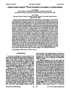
I. INTRODUCTION During the design phase of the Advanced Photon Source (APS), much consideration was given to the requirement for micron-scale beam stability [1]. At that time, it was envisioned that x-ray beam position monitors would be used for local closed-loop steering of individual user beam lines. To that end, a significant effort was put into the mechanical and electrical design and construction of a complement of photoemission x-ray “blade” monitors, so called because metallized synthetic diamond wafers are placed edge-on to the x-ray beam [2]. It is important to understand the geometry and nomenclature for the X-BPM (beam position monitor) blade monitors presently in use at the APS. Figure 1 is a schematic diagram indicating the labeling and geometry for both the upstream (P1) and downstream (P2) X-BPMs presently installed in all APS insertion device beam line front ends. Note that the center of the storage ring is on the right-hand side of Fig. 1; i.e., the view is from inside the accelerator looking outward. The mechanical support structure for these devices was carefully designed to minimize the effects of ground vibration and temperature fluctuations; i.e., they resemble hollow pillars, filled with sand and carefully insulated. Unfortunately, it has not been possible to capitalize on these excellent mechanical and thermal design characteristics on insertion device beam lines as a consequence of multiple sources of stray radiation, which impinge upon the x-ray BPM blades. At the APS, this stray radiation emanates not only from the two main dipole magnets located at the upstream and downstream ends of each insertion device straight section, but also from each of six steering corrector magnets and from off axis particle beam trajectories through six quadrupole and four sextupole magnets. As a result, the stray radiation backgrounds are variable, for example, when local bending magnet beam line steering is performed. Normal charged particle beam closed-orbit correction at the APS employs up to 360 broad band “monopulse” 1098-4402兾99兾2(11)兾112801(10)$15.00
radio frequency (rf) receivers for position monitoring of the charged particle beam in addition to 42 narrow band BPMs. These rf electronics are used for both dc and ac feedback with correction bandwidth up to 50 Hz [3]. Some of the many systematic effects impacting these devices are electron bunch fill pattern dependence, beam intensity dependence, and earth tidal force-induced accelerator circumference variation [4]. This system’s most challenging task is fill-to-fill reproducibility. Presently the particle beam lifetime is such that reinjection of electrons into the APS storage ring occurs nominally once per day. Because 5 m typically separates the rf BPM stations straddling an insertion device, while an insertion device beam line might be as long as 80 m, a lever arm as large as a factor of 16 is possible. This lever arm amplification of rf BPM systematic errors is one of the primary motivations for seriously pursuing a solution to the x-ray BPM stray radiation problem. The x-ray BPMs on each insertion device beam line are located approximately 16.3 and 20.1 m, respectively, from the center of the insertion device straight section where the source point is located. An algorithm that fixes the average of the two X-BPMs along with the average of the two source point rf BPMs could, in principle, provide superior angular pointing stability in comparison to using either system alone, depending on the levels of systematic errors involved.
FIG. 1. APS ID x-ray BPM geometry and nomenclature.
© 1999 The American Physical Society
112801-1
PRST-AB 2
GLENN DECKER AND OM SINGH
112801 (1999)
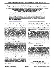
II. DESCRIPTION OF ACCELERATOR LATTICE MODIFICATION CONCEPT Figure 2 shows the locations of accelerator components near the insertion device source point in a typical APS sector. Two quadrupole magnet triplets straddle each APS insertion device. Additionally, each straight section is provided with a total of six combined-function horizontal/ vertical steering corrector magnets that allow a large degree of flexibility in the choice of orbit correction algorithms. The sextupole magnets shown are required to increase the accelerator’s dynamic aperture. Figure 3 illustrates a concept for displacing the insertion device in such a way that stray radiation from multipoles and corrector magnets will be directed away from the x-ray BPMs. The idea is to reduce the bend angle of the main dipole magnets by 1 mrad and make up for this deficiency using steering correctors located immediately upstream and downstream from the insertion device. This entails realignment of the girders supporting the magnets in order to confine the charged particle beam’s closed orbit to the centers of the multipole magnets. One apparent problem with the concept shown in Fig. 3 is that it requires displacing not only the insertion device but also the entire x-ray beam line. Because there are a large number of insertion device beam lines already in operation at the APS, this concept is not too attractive. An alternative concept, shown in Fig. 4, is to leave the insertion device and beam line components alone and move the accelerator components from two adjacent sectors in the opposite direction. While this sounds a bit outlandish, it is, in fact, a perfectly viable option and was executed on APS sector 34. The closed orbit trajectories in Fig. 4 are shown in curvilinear coordinates with the variable s being a measure of arc length along the unperturbed closed orbit. This is in contrast to Figs. 2 and 3, which correspond to a Cartesian coordinate system.
X-ray BPMs (16, 20 meters from source) Insertion Device
ID photons
Main Dipole Bend Magnet
5 meters 78 mrad
Legend
Positron Trajectory
Focusing Quadrupole Magnet Defocusing Quadrupole Magnet Sextupole Magnet Combined Function Horz./ Vert. Steering Corrector Magnet
FIG. 2. Schematic of APS insertion device straight section.
112801-2
FIG. 3. Concept for redirecting stray radiation from x-ray BPMs.
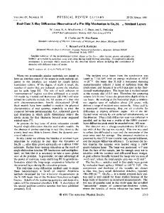
III. IMPLEMENTATION A. Ray tracing While the concept described above might appear straightforward, a significant effort was required to assure that such a major lattice change could be executed without adversely affecting accelerator operation. Not least among the challenges faced was the derivation of new survey coordinates that would satisfy the constraint that the nominal closed-orbit pass through the magnetic center of all affected quadrupole and sextupole magnets. Once a set of hand-calculated values was derived, an extensive ray tracing effort was initiated. This effort, in addition to validating the calculated coordinate changes, gave assurance that no uncooled surfaces would be struck by bending magnet radiation. Ray tracing also provided alignment information for the bending magnet beam lines. While the alternative modification shown in Fig. 4 explicitly leaves the insertion device beam line unperturbed, the bending magnet beam line source points are significantly affected. The primary impact is that the source point is displaced by approximately 6 mm inboard, while the horizontal beam axis is rotated outboard by almost 0.5 mrad. Depending on whether or not imaging is performed, the effect on specific bending magnet x-ray experiments varies. For those beam lines not employing imaging, the net result is simply that a different portion of the bending magnet “fan” of radiation will be transported down the existing beam line, offset by about 0.5 mrad. On the other hand, at beam line 35-BM, which employs a pinhole camera as a particle beam diagnostic, for example, realignment of in-tunnel apertures along with a detector were necessary. Shown in Fig. 5 is a comparison of the ray tracing analysis before and after the girder realignment, in plan view. The crosshatched areas represent regions where bending magnet radiation, streaming from left to right, strikes the triangular “crotch” absorber and the smaller “wedge” absorber at the top of the figures. The upper crosshatched area is the dipole radiation fan originating 112801-2
PRST-AB 2
METHOD FOR REDUCING X-RAY BACKGROUND …
112801 (1999)
FIG. 4. Alternative concept for accelerator realignment.
from the main dipole bend magnet located upstream of the insertion device source point, while the lower crosshatched areas correspond to the downstream dipole’s radiation fan. The charged particle beam trajectory lies along the lower (i.e., inboard) edge of the bending magnet fan that strikes the crotch absorber. The particle beam passes through the center of the vacuum spool piece that can be seen at the lower right on both diagrams. The insertion device x-ray beam centerline coincides with the boundary between the upper and lower crosshatched areas on the left and is shown separately in the “after” drawing on the right. This portion of the APS vacuum chamber Upstream Dipole X-radiation Fan Before Modification
Downstream Dipole X-radiation Fan
is located immediately downstream of the downstream dipole magnet of Figs. 2 and 3, very near the point where the insertion device x rays exit the accelerator and enter the beam line front end. B. Missteering and top-up analysis After the ray tracing for an unperturbed beam was completed, it was necessary to perform a tolerance study for various combinations of horizontal and vertical missteering. The missteering cases studied were derived from accelerator acceptance values resulting from vacuum Insertion Device X-rays After Modification
Charged Particle Beam Trajectory
FIG. 5. (Color) Ray tracing results before (left) and after (right) girder displacement.
112801-3
112801-3
PRST-AB 2
GLENN DECKER AND OM SINGH
chamber apertures. The end result of all of this was that the girder realignment shown in Fig. 4 is acceptable from a beam missteering point of view; i.e., no uncooled surfaces are irradiated by bending magnet synchrotron radiation. A second type of ray tracing was necessary to assure that the proposed change would be compatible with accelerator top-up operation. Briefly, top-up is defined as injection with user beam line shutters open. The topup safety ray tracing analysis assures that, in the presence of stored beam, it is impossible for the injected beam to be transported down an x-ray beam line. Special detectors are interlocked to prevent injection from zero stored beam, since the expected top-up failure mode is injection with a shorted dipole magnet, which is incompatible with the presence of stored beam. The ray tracing actually is done in reverse; if it can be shown that an imaginary beam injected into the accelerator back along an x-ray beam line cannot thread its way back to the small-aperture insertion device vacuum chamber under varying magnet error conditions, then success is declared [5]. The trip limits for the insertion device beam missteering interlock required adjustment since the girder realignment changed the relation between the intense insertion device x-ray beam and the vacuum components needing protection. Specifically, because the accelerator moved inboard, a smaller amount of outboard horizontal steering could be tolerated on the insertion device beam. C. Lattice modification and compensation The change in strength of four out of the 80 main dipole magnets was accomplished with dc-to-dc converter power supplies connected to auxiliary dipole trim windings available on all dipole magnets. These power supplies were developed concurrently with the work described herein. A final design was successfully tested for reliability during an early operating period by using nearby corrector magnets to build a local bump in combination with each of two trim supplies powered in an unused sector without beam lines. The change in dipole strength and displacement of the closed orbit made a small change to the accelerator lattice functions. One of the largest effects was that the circumference of the accelerator was decreased by 0.89 mm per sector, i.e., 1.78 mm for the change shown in Fig. 4. This implies that the rf frequency (nominally 351.927 MHz) needed to increase by 568.0 Hz, which is well within the 63 MHz design tuning range of the rf cavities [1]. Implementing the change in all 40 APS sectors would require an increase of rf frequency of 11.4 kHz, still well within the tuning range. During normal accelerator operation, the rf frequency is varied continuously to compensate for earth tide-induced accelerator circumference variations. The closed orbit is thus held close to the center of the 40 high-dispersion quadrupoles. 112801-4
112801 (1999)
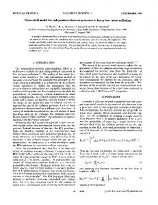
To compensate for changes in the dispersion and beta functions, off-line modeling was performed to calculate quadrupole strength changes necessary to match the beta functions in the center of the insertion device straight section and to provide zero dispersion at the insertion device source points. Magnetic measurement data for the horizontal corrector magnets were used to compute the required power supply currents necessary to generate 1.0 mrad of steering immediately upstream and downstream of the insertion device. A total of 81 main dipole magnets were wired in series, 80 of them to provide 360± of bend, with the 81st magnet installed on the tunnel floor to provide a temperature-tracked calibration reference. An NMR probe was installed in the gap of this 81st dipole and was used to develop a standardization cycle for the main dipole circuit that resulted in 76 standard strength magnets and four magnets with 1.0 mrad less bend angle than nominal. Figure 6 shows plots of the measured dispersion function with uncorrected and corrected quadrupole settings. The upper trace employed the new dipole and corrector settings only, using quadrupole settings from the previous operating period, while the lower trace shows the effects of ramping to the calculated quadrupole settings derived from the matching conditions; i.e., it is the result of dead reckoning from a computer model. As can be inferred from the existence of the data in Fig. 6, the modification to the accelerator lattice described in the preceding sections was carried out and beam was successfully stored. There were no inherent difficulties in recommissioning the ring beyond those anticipated. The girder motion took place during the December 1998 machine maintenance period and required three surveyor crew shifts for each of the two displaced sectors. Because a vacuum intervention was planned in one of the sectors for other reasons, one of the short, approximately 5 in. long, spool pieces joining adjacent vacuum chambers was removed and inspected. No damage from the mechanical movement was seen, which was reassuring, considering that the girder move was deliberately made under vacuum in order to execute the modification as quickly as possible. IV. EXPERIMENTAL RESULTS Figure 7 gives a comparison of data from two insertion device beam lines, one without the lattice modification (beam line 1-ID), and the second, 34-ID, modified according to the alternative scheme shown in Fig. 4. The sum of the photocurrents from each of four blade sensors is plotted for the upstream (P1) and downstream (P2) x-ray BPMs as a function of insertion device gap. As can be seen from the figure, the signal level with the gap open (50 mm or greater) is significantly reduced by the lattice modification, nearly an order of magnitude for P1 and over a factor of 2 for P2. 112801-4
PRST-AB 2
METHOD FOR REDUCING X-RAY BACKGROUND …
112801 (1999)
FIG. 6. Experimental data showing dispersion before (top) and after (bottom) matching.
The motivation for choosing the blade geometry shown in Fig. 1 was to prevent the upstream BPM’s blades from shadowing the downstream blades, while at the same time avoiding the bending magnet radiation fans located immediately inboard and outboard of the insertion device centerline as indicated in Fig. 5. It is important to point out that, while moving the accelerator components is expected to have eliminated the upstream and downstream bending magnet radiation from the X-BPM
field of view, synchrotron radiation from the two horizontal correctors located immediately upstream and downstream of the source point (Fig. 3) is still present. This is presumably the reason behind the small, but nonzero, signal seen on the ID-34 signals with large gap values in Fig. 7. In support of this conclusion is the observation that blades E and F of the downstream P2 X-BPM show the largest signal with the insertion device gap open. The large overlap of these blades (Fig. 1) with
Unmodified Sector 1-ID Modified Sector 34-ID
Insertion device gap (mm)
Downstream X-ray BPM
P2 Blade Signal Sum (µAmps)
P1 Blade Signal Sum (µAmps)
Upstream X-ray BPM
Insertion device gap (mm)
FIG. 7. Variation of insertion device X-BPM blade signal sum with gap.
112801-5
112801-5
PRST-AB 2
GLENN DECKER AND OM SINGH
the corrector magnet radiation fans would explain this observation. Variation of position readbacks with gap It is well known that the magnetic field produced from hybrid insertion devices such as those used at the APS varies approximately exponentially with gap. Indeed, the data displayed in Fig. 7 can be fit quite well by a function of the form Y 苷 a 1 b exp共2gG兲 ,
(1)
where G is the insertion device gap, and a, b, and g are fitting parameters. Not only does the sum signal of Fig. 7 fit this form, but each individual blade signal similarly can be fit in this manner, although each blade in general is found to have different characteristic fit parameters a, b, and g. Further, the fit parameters for each blade signal have been found to depend on the centroid position of the x-ray beam. In order to make a fair comparison between position readback variation with gap for the modified and unmodified sectors, a series of “gap scans” was performed for the two cases. The position of the x-ray beam’s centroid was varied for each scan by making use of a local steering correction employing four steering corrector magnets straddling the insertion device straight sections, configured in similar fashion for the two insertion device x-ray source points. For each gap scan, all eight x-ray BPM blade signals for each insertion device were fit to a function of the form of Eq. (1). To compute position from the four blade signals, ratios of differences and sums are computed according to X1 苷 KX1 共A 2 B 1 C 2 D兲兾共A 1 B 1 C 1 D兲 ,
(2)
Y1 苷 KY1 共A 1 B 2 C 2 D兲兾共A 1 B 1 C 1 D兲
(3)
for the upstream x-ray BPM of Fig. 1, and X2 苷 KX2 共E 2 F兲兾共E 1 F兲 ,
(4)
Y2 苷 KY2 共A 2 B兲兾共A 1 B兲
(5)
for the downstream geometry. The results Xn and Yn , n 苷 1, 2 define the horizontal and vertical readbacks, respectively, for the upstream 共n 苷 1兲 and downstream 共n 苷 2兲 x-ray BPMs. The constants KX1 , KY1 , KX2 , and KY2 are geometry-dependent sensitivity factors with dimensions of length. For the x-ray BPM used at the APS, the geometry was chosen such that these factors generally have magnitude between 1 and 2 mm. They were determined for the data presented here by cross calibrating the two x-ray BPMs against two rf BPMs straddling the insertion device source point. It turns out that the “constant” terms a of Eq. (1) for the individual blade signals introduce an overwhelming contribution to these ratios for the unmodified sector in 112801-6
112801 (1999)
comparison to a modified sector, resulting in a large variation of “position” readback with gap. This is simply a result of the relatively large contribution to the blade signals resulting from the background stray radiation impinging on the blades for the unmodified sectors. To make a more fair comparison, a background subtraction technique was used in the analysis of the gap scan data. Prior to calculating the ratios of Eqs. (2)–(5), an average coefficient a was subtracted from each blade signal. For each blade, a set of fit constants a corresponding to the set of gap scans was derived. The average of these values was then subtracted from all of the data for this blade, for all of the gap scans. A total of eight such fit constants were extracted from the data sets, one for each blade. Thus the computed positions do not reflect the absolute size of the background, but rather show the effects of the variation of the background signals as the beam position is varied (in addition to the effects of variation of the other two fit coefficients with beam position). Shown in Figs. 8 and 9 are a set of processed position signals plotted as a function of insertion device gap, after following the background subtraction procedure just described. Figure 8 corresponds to the unmodified case (1-ID), while Fig. 9 is data for the modified sector (34-ID). The different curves on each of the plots are gap scan data for differing horizontal positions. The horizontal and vertical positions were held constant for each curve by making use of the rf beam position monitor system. Note that the dominant effect seen for the unmodified case is a large amount of coupling from horizontal motion into the vertical readback. This effect is reduced markedly by the modification. The vertical variation seen in the modified case is small and could be a result of steering internal to the insertion device. For example, it is well known that insertion devices focus in the vertical plane, so a vertical orbit distortion internal to the device (i.e., not correctable with standard APS orbit correction) is a possibility. While not as apparent, there is a significant reduction in the variation of horizontal readback with gap, approximately a factor of 2, together with an improvement in symmetry. Proceeding further with the investigation of the residual open-gap signals, Figs. 10 and 11 show the effects of a “local bump” scan through the downstream and upstream dipole magnets, respectively. The measurements involved using a combination of corrector magnets to steer the beam at either of the two dipole magnet source points without changing the orbit through either the insertion device or the other dipole magnet. These bumps are routinely used to make small steering corrections for individual beam lines without affecting other users, albeit with much smaller amplitudes than those indicated in Figs. 10 and 11. Plotted in each figure are the individual blade signals in microamperes as a function of the steering angle through the dipole magnets (due to the geometry, 112801-6
PRST-AB 2
METHOD FOR REDUCING X-RAY BACKGROUND …
112801 (1999)
Vertical Readback (mm)
Horizontal Readback (mm)
Unmodified Sector (1-ID) Upstream X-ray BPM
Insertion Device Gap (mm)
Insertion Device Gap (mm)
Vertical Readback (mm)
Horizontal Readback (mm)
Unmodified Sector (1-ID) Downstream X-ray BPM
Insertion Device Gap (mm)
Insertion Device Gap (mm)
FIG. 8. (Color) Variation of computed x-ray BPM position with insertion device gap, as a function of horizontal steering for the unmodified sector.
Vertical Readback (mm) Insertion Device Gap (mm) Insertion Device Gap (mm) Modified Sector (34-ID) Downstream X-ray BPM
Vertical Readback (mm)
Horizontal Readback (mm)
Horizontal Readback (mm)
Modified Sector (34-ID) Upstream X-ray BPM
Insertion Device Gap (mm)
Insertion Device Gap (mm)
FIG. 9. (Color) Variation of computed x-ray BPM position with insertion device gap, as a function of horizontal steering for the modified sector.
112801-7
112801-7
PRST-AB 2
GLENN DECKER AND OM SINGH Unmodified Sector Upstream X-ray BPM
Unmodified Sector Downstream X-ray BPM
Sector 1-ID
Modified Sector Upstream X-ray BPM Sector 34-ID
P2 Blade Signals (µAmps)
P1 Blade Signals (µAmps)
Sector 1-ID
Vertical Angle (mrad)
112801 (1999)
Vertical Angle (mrad)
Modified Sector Downstream X-ray BPM Sector 34-ID
Vertical Angle (mrad)
Vertical Angle (mrad)
FIG. 10. Response of ID BPM blade signals to downstream dipole local bump scan.
the X-BPMs are most sensitive to angle, rather than parallel displacement). Results from the unmodified sector 1-ID are indicated in the top two frames of each figure, while the modified sector 34-ID data are shown in the bottom two frames.
Unmodified Sector Upstream X-ray BPM
From Fig. 10 one can clearly see that downstream dipole radiation has been essentially eliminated from the field of view of the modified 34-ID X-BPMs, as desired. The large peak in the upper right-hand panel of Fig. 10 is the infamous “F blade” of the downstream P2 X-BPM
Unmodified Sector Downstream X-ray BPM
Vertical Angle (mrad) Modified Sector Upstream X-ray BPM Sector 34-ID
Vertical Angle (mrad)
FIG. 11.
112801-8
Sector 1-ID
P2 Blade Signals (µAmps)
P1 Blade Signals (µAmps)
Sector 1-ID
Vertical Angle (mrad) Modified Sector Downstream X-ray BPM Sector 34-ID
Vertical Angle (mrad)
Response of ID BPM blade signals to upstream dipole local bump scan.
112801-8
PRST-AB 2
METHOD FOR REDUCING X-RAY BACKGROUND …
on 1-ID. By comparison with the gap scan data of Fig. 7, it is seen that the signal on this blade originating from the downstream dipole with moderate vertical steering is nearly one-third of the sum signal with the gap completely closed and with the standard beam line alignment. Figure 11 shows the reduction in sensitivity to vertical steering in the upstream dipole magnet. This source is quite distant from the X-BPMs, greater than 25 m away. Apparently, some reflections are able to thread their way through the small-aperture insertion device vacuum chamber and strike the blades even after the modification. Note the change in vertical scale on the right-hand frames in Fig. 11 in comparison to Fig. 10. While Figs. 10 and 11 indicate that the dipole magnet radiation has been reduced to a significant degree, what remains is to show the characteristics of the synchrotron radiation emanating from the 1 mrad of steering in the horizontal corrector magnets located immediately upstream and downstream of the insertion device source point (Fig. 3). For this purpose, a local, asymmetric (i.e., primarily angular) bump was constructed to modify both the vertical and horizontal angle of the charged particle beam as it passes through the insertion device. This was accomplished without adjusting the field in the 1 mrad correctors to assure that the synchrotron radiation x rays from these two correctors would move in sympathy as the trajectory was varied. Figures 12 and 13 show the results of the vertical and horizontal insertion device steering with the insertion device gap open.
Note the top-bottom symmetry, seen in the bottom frames of Fig. 12 as the beam is steered vertically, on all blades of the upstream X-BPM and on the A and B blades of the downstream X-BPM on 34-ID. Note also that as the beam is steered downward, the 34-ID P2 E and F blades exhibit a maximum value. The observation that the F blade’s peak signal is larger than the E blade can be explained by noting that it is the downstream corrector magnet’s radiation that predominantly strikes F, while the upstream corrector, which is 6.5 m more distant, is apparently responsible for the signal on the E blade. In Fig. 13, one sees very little dependence on horizontal steering at 34-ID until relatively large angles are reached. This increase apparently arises from horizontally off axis corrector magnet radiation, which one would expect to peak at angle values of 60.5 mrad, i.e., one-half of the total corrector’s bend angle. The properties of the off axis corrector radiation suggest the potential to provide a powerful, gap-independent x-ray position diagnostic. Because there are no variable magnetic elements between the two correctors (including the correctors themselves) with the exception of the insertion device, which has been optimized to reduce any steering effects, one would expect the correctors’ radiation pattern centroid positions to track well with insertion device beam motion. A set of x-ray blades arranged in a fashion similar to the P1 blades of Fig. 1 but displaced horizontally into the “cracks” between the insertion device axis and the inboard or outboard bending magnet fans (Fig. 5) could conceivably provide such a gap-independent position diagnostic.
Unmodified Sector Downstream X-ray BPM
Unmodified Sector Upstream X-ray BPM
Modified Sector Upstream X-ray BPM Sector 34-ID
Vertical Angle (mrad)
FIG. 12.
112801-9
Sector 1-ID
P2 Blade Signals (µAmps)
P1 Blade Signals (µAmps)
Sector 1-ID
Vertical Angle (mrad)
112801 (1999)
Vertical Angle (mrad) Modified Sector Downstream X-ray BPM Sector 34-ID
Vertical Angle (mrad)
Variation of X-BPM blade voltages with vertical steering through ID straight, with the insertion device gap open.
112801-9
PRST-AB 2
GLENN DECKER AND OM SINGH Unmodified Sector Upstream X-ray BPM
Unmodified Sector Downstream X-ray BPM
Sector 1-ID
Modified Sector Upstream X-ray BPM Sector 34-ID
Horizontal Angle (mrad)
FIG. 13.
Horizontal Angle (mrad) Modified Sector Downstream X-ray BPM Sector 34-ID
Horizontal Angle (mrad)
Variation of X-BPM blade voltages with horizontal ID steering, with the insertion device gap open.
V. CONCLUSIONS A technique has been developed at the Advanced Photon Source that provides a drastic reduction in stray radiation background signals on insertion device x-ray beam position monitors. The radiation remaining after displacing accelerator girders appears to be small and easily understood. It is expected that implementation of this lattice change will, for the first time, enable local dc orbit correction at the submicron scale to be performed, yielding reproducible x-ray beam position over periods of weeks or longer. ACKNOWLEDGMENTS This work is the result of an extensive, cooperative effort between members of both the APS Accelerator Systems Division and Experimental Facilities Division known as the XFD/ASD X-ray Stability Task Force (XAXSTF). This work would not have been possible without the support of David Moncton, who was instrumental in its success. Louis Emery performed the work behind Fig. 6.
112801-10
P2 Blade Signals (µAmps)
P1 Blade Signals (µAmps)
Sector 1-ID
Horizontal Angle (mrad)
112801 (1999)
This work was supported by the U.S. Department of Energy, Office of Basic Energy Science, under Contract No. W-31-109ENG-38.
[1] Argonne National Laboratory Report No. ANL-87-15, 1987. [2] D. Shu, B. Rodricks, J. Barraza, T. Sanchez, and T. M. Kuzay, Nucl. Instrum. Methods Phys. Res., Sect. A 319, 56 (1992). [3] J. Carwardine and F. Lenkszus, in Proceedings of the 1998 Beam Instrumentation Workshop, edited by R. Hettel, S. Smith, and J. Masek, AIP Conf. Proc. No. 451 (AIP, New York, 1998), p. 125. [4] G. Decker, J. Carwardine, and O. Singh, in Proceedings of the 1998 Beam Instrumentation Workshop, edited by R. Hettel, S. Smith, and J. Masek, AIP Conf. Proc. No. 451 (AIP, New York, 1998), p. 237. [5] L. Emery and M. Borland, in Proceedings of the 1999 Particle Accelerator Conference (PAC99), New York (to be published).
112801-10